Remove the QFX5700 Switch
To power off and remove a QFX5700 Switch, read the following sections.
Power Off a QFX5700 Switch
Before you power off a QFX5700 switch.
-
Ensure that you have taken the necessary precautions to prevent electrostatic discharge (ESD) damage. See Prevention of Electrostatic Discharge Damage.
-
Ensure that you don’t need to forward traffic through the switch.
-
Ensure that you have the following parts and tools available to power off the switch:
-
An ESD grounding strap
-
An external management device such as a PC
-
An RJ-45 to DB-9 rollover cable to connect the external management device to the console port on one of the Routing and Control Boards (RCBs)
-
To power off a QFX5700 switch:
Remove a QFX5700 from a Four-Post Rack Using a Mechanical Lift
Before you remove the switch using a lift:
Ensure that the rack is stable and secured to the building.
Ensure that there is enough space to place the removed switch in its new location and along the path to the new location.
Review the chassis lifting guidelines described in Chassis and Component Lifting Guidelines.
Ensure that the switch is safely powered off.
Ensure that you have the following parts and tools to remove the switch:
A Phillips (+) screwdriver, number 2 or number 3, depending on the size of your mounting screws
When removing more than one switch chassis from a rack, remove the switches in order from top to bottom.
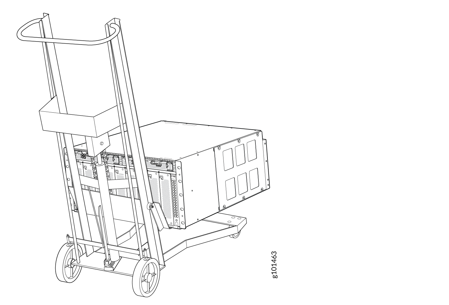
Because of the switch's size and weight, we strongly recommend that you use a mechanical lift to install the QFX5700.
To remove the switch using a mechanical lift:
- Use the lift to transport the switch to its new location.Figure 1: Move the QFX5700 Using a Mechanical Lift
Manually Remove a QFX5700 from a Four-Post Rack
Before you manually remove the switch from a rack:
Ensure that the rack is stable and secured to the building.
Ensure that there is enough space to place the removed switch in its new location and along the path to the new location.
Review the chassis lifting guidelines described in Chassis and Component Lifting Guidelines.
Ensure that the switch is safely powered off.
Ensure that you have a Phillips (+) screwdriver, number 2 or number 3, depending on the size of your mounting screws.
If you cannot use a mechanical lift to remove the switch (the preferred method), you can install it manually.
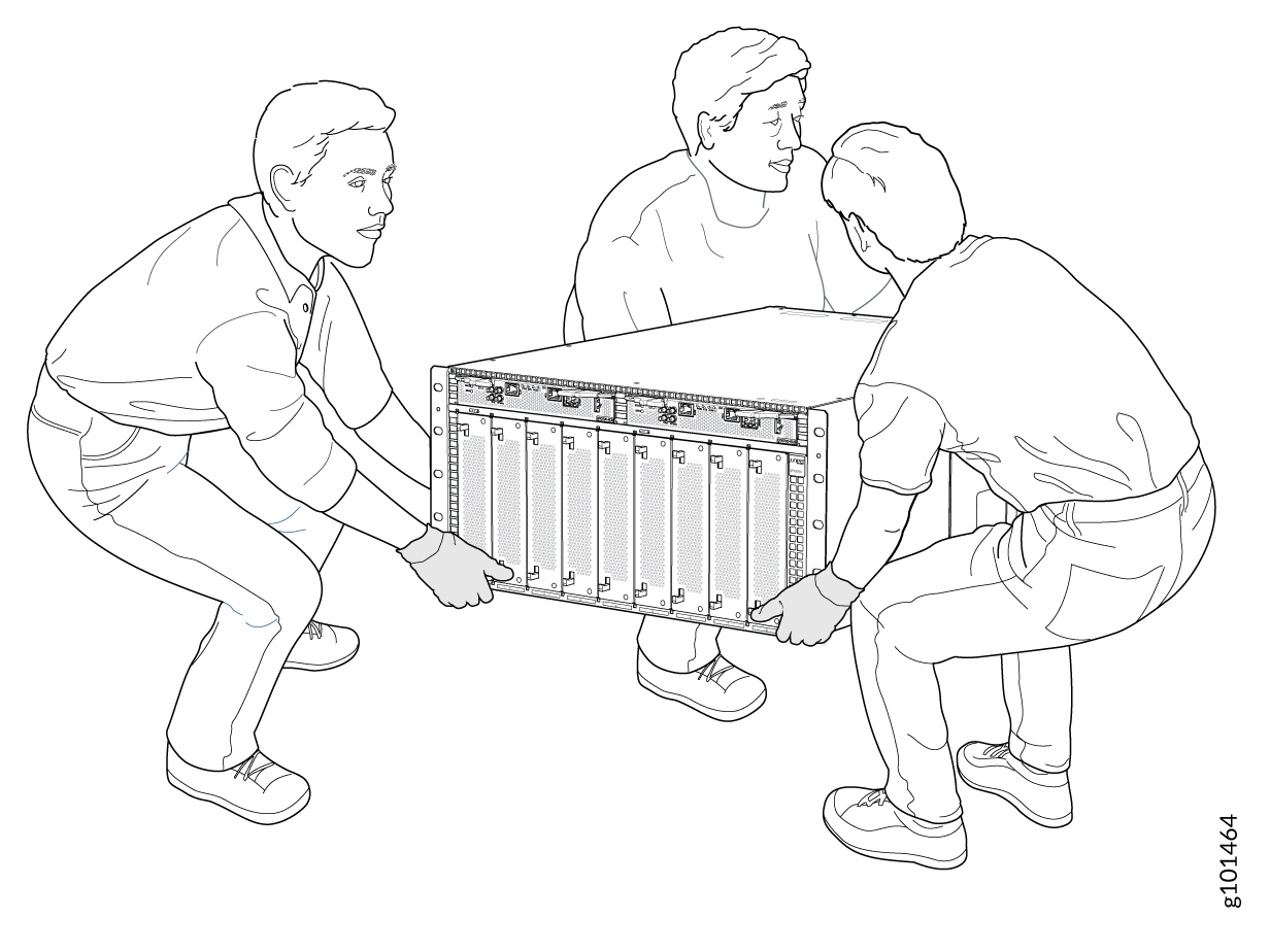
The chassis weighs approximately 110 lb (50 kg) with only the fan tray controllers installed. Lifting the chassis and mounting it in a rack or cabinet requires at least three people.
Make sure the chassis is empty (contains only the fan tray controllers) before you lift it.
When removing more than one switch chassis from a rack, remove the switches in order from top to bottom.
To manually remove a QFX5700 from a rack:
- Carefully lift it out of rack. If you have a pallet jack,
move the switch onto the pallet jack. See Figure 2.Figure 2: Lift the QFX5700 Without Using a Mechanical Lift