Maintaining the SRX4600 Power System
Maintaining SRX4600 Firewall Power Supplies
Purpose
For optimum firewall performance, verify the condition of the power supplies.
Action
On a regular basis:
To check the status of the power supplies, issue the
show chassis environment pemcommand. The output shown below is an example.user@host> show chassis environment pem PEM 0 status: State Online Airflow Front to Back Temperature OK 45 degrees C / 113 degrees F Temperature OK 39 degrees C / 102 degrees F Temperature OK 28 degrees C / 82 degrees F Firmware version 04.10 Fan 0 9232 RPM DC Output Voltage(V) Current(A) Power(W) Load(%) 12.00 16 192 6 PEM 1 status: State Online Airflow Front to Back Temperature OK 42 degrees C / 107 degrees F Temperature OK 35 degrees C / 95 degrees F Temperature OK 26 degrees C / 78 degrees F Firmware version 04.10 Fan 0 8896 RPM DC Output Voltage(V) Current(A) Power(W) Load(%) 12.00 18 216 7Make sure that the power and grounding cables are arranged so that they do not obstruct access to other firewall components.
Routinely check the status LEDs on the power supply faceplates to determine whether the power supplies are functioning normally. Each power supply faceplate displays a single LED to indicate the status of the power supply.
Check the alarm LEDs on the front panel of the device. Power supply failure or removal triggers an alarm that causes one or both of the LEDs to light. You can display the associated error messages by issuing the following command:
user@host> show chassis alarms
Periodically inspect the site to ensure that the grounding and power cables connected to the device are securely in place and that there is no moisture accumulating near the device.
Replacing an SRX4600 Firewall AC Power Supply
Each power supply is a field-replaceable unit (FRU) installed in the rear panel of the SRX4600 Firewall. You can remove and replace a power supply without powering off the firewall or disrupting firewall functions.
All the power supplies must be installed and operational for optimal functioning of the firewall.
Removing the SRX4600 Firewall AC Power Supply
Ensure that you have the following tools and parts available:
-
Electrostatic discharge (ESD) grounding strap
-
An antistatic bag or an antistatic mat
-
Phillips (+) screwdriver, number 1
-
A cover panel for the power supply slot
You can remove an AC power supply without powering off the firewall or disrupting firewall functions.
Before you remove a power supply from the firewall, ensure that you have taken the necessary precautions to prevent ESD damage (see Prevention of Electrostatic Discharge Damage).
We recommend that you install either a replacement power supply or a cover panel in the empty power supply slot to prevent chassis overheating and dust accumulation.
After powering off a power supply, wait at least 60 seconds before turning it back on.
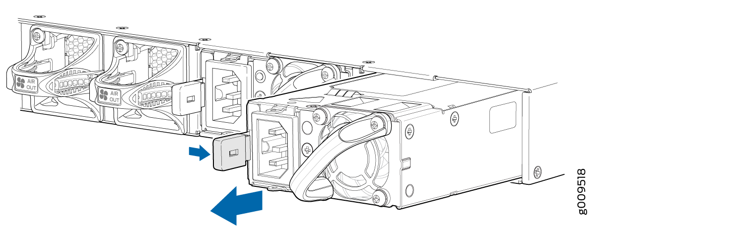
To remove an AC power supply, see (Figure 1):
- If the AC power source outlet has a power switch, set it to the off (O) position. Follow the instructions for your site.
- Attach an ESD grounding strap to your bare wrist and connect the strap to one of the ESD points on the chassis.
- Place the antistatic bag or the antistatic mat on a flat, stable surface.
- Gently pull out the plug end of the power cord connected to the power source outlet.
- Remove the power cord from the power supply faceplate by detaching the power cord retainer and gently pulling out the socket end of the power cord connected to the power supply faceplate.
- Slide the release latch to the left to unseat the power supply from the chassis. See Figure 1.
- Grasp the power supply handle and pull firmly to slide the power supply halfway out of the chassis.
- Place one hand under the power supply to support it and slide it completely out of the chassis. Take care not to touch power supply components, pins, leads, or solder connections.
- Place the power supply in the antistatic bag or on the antistatic mat placed on a flat, stable surface.
- If you are not replacing the power supply, install the cover panel over the slot.
Installing the SRX4600 Firewall AC Power Supply
Ensure that you have the following tools and parts available:
-
ESD grounding strap
-
Phillips (+) screwdriver, number 1
You can install an AC Power Supply without powering off the firewall or disrupting firewall functions.
Before you install a power supply from the firewall, ensure that you have taken the necessary precautions to prevent ESD damage (see Prevention of Electrostatic Discharge Damage).
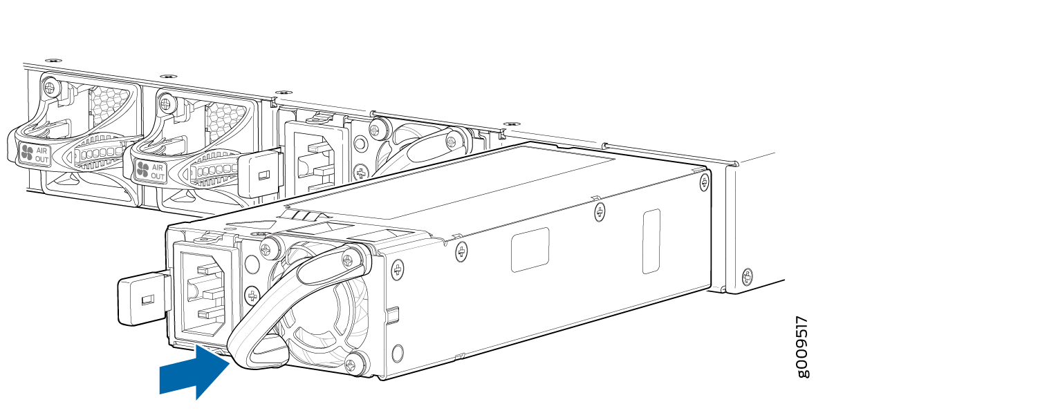
To install the AC power supply, see (Figure 2):
- Attach the ESD grounding strap to your bare wrist, and connect the strap to the ESD point on the chassis.
- Taking care not to touch power supply pins, leads, or solder connections, remove the power supply from the bag.
- Using both hands, place the power supply in the power supply slot on the rear panel of the firewall and slide it in until it is fully seated and slide the release latch to the right.
- Insert the socket end of the power cord into the faceplate of the power supply and attach the power cord retainer.
- Insert the plug end of the power cord to the power source outlet.
- On the AC power source outlet, set the power switch to on (I) position. Follow the instructions for your site.
- Observe the status LED on the power supply faceplate. If the power supply is correctly installed and functioning normally, the status LED glows green steadily.
If you have a Juniper J-Care service contract, register any addition, change, or upgrade of hardware components at https://www.juniper.net/customers/support/tools/updateinstallbase/ . Failure to do so can result in significant delays if you need replacement parts. This note does not apply if you replace existing components with the same type of component.
Replacing an SRX4600 Firewall DC Power Supply
Each power supply is a field-replaceable unit (FRU) installed in the rear panel of the SRX4600 Firewall. You can remove and replace a power supply without powering off the firewall or disrupting firewall functions.
All the power supplies must be installed and operational for optimal functioning of the firewall.
Removing the SRX4600 Firewall DC Power Supply
Ensure that you have the following tools and parts available:
-
Electrostatic discharge (ESD) grounding strap
-
An antistatic bag or an antistatic mat
-
Socket nut driver
-
A cover panel for the power supply slot
You can remove a DC power supply without powering off the firewall or disrupting firewall functions.
Before you remove a power supply from the firewall, ensure that you have taken the necessary precautions to prevent ESD damage (see Prevention of Electrostatic Discharge Damage).
Before performing DC power procedures, ensure that power is removed from the DC circuit. To ensure that all power is off, locate the circuit breaker on the panel board that services the DC circuit, switch the circuit breaker to the off (O) position, and tape the switch handle of the circuit breaker in the off position.
We recommend that you install either a replacement power supply or a cover panel in the empty power supply slot to prevent chassis overheating and dust accumulation.
After powering off a power supply, wait at least 60 seconds before turning it back on.
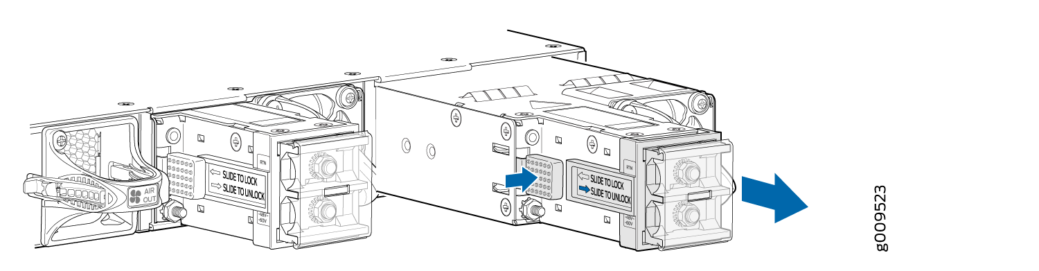
To remove a DC power supply, see Figure 4
- Attach an ESD grounding strap to your bare wrist and connect the strap to one of the ESD points on the chassis.
- Place the antistatic bag or the antistatic mat on a flat, stable surface.
- Make sure that the voltage across the DC power source cables leads is 0 V and that there is no chance that the cables might become active during the removal process.
- Remove the protective cover from the input terminals. Save the protective cover for later use.
- Using the socket nut driver remove the M5 K-nuts from each of the DC power terminals. See Figure 3.
- Remove the cable lugs from the input DC terminals and carefully move the power cables out of the way.
- Replace the protective cover onto the input terminals.
- Slide the latch lock to allow the retention latch of the power supply to disengage from the chassis slots.
- Grasp the power supply handle and pull firmly to slide the power supply halfway out of the chassis.
- Place one hand under the power supply to support it. Grasp the power supply handle with your other hand and pull the power supply completely out of the chassis.
- Place the power supply in the antistatic bag or on the antistatic mat placed on a flat, stable surface.
- If you are not immediately replacing the power supply, install the cover panel over the slot.
Installing the SRX4600 Firewall DC Power Supply
Ensure that you have the following tools and parts available:
-
ESD grounding strap
-
An antistatic bag or an antistatic mat
-
Socket nut driver
You can install an DC Power Supply without powering off the firewall or disrupting firewall functions.
Before you remove a power supply from the firewall, ensure that you have taken the necessary precautions to prevent ESD damage (see Prevention of Electrostatic Discharge Damage).
Before performing DC power procedures, ensure that power is removed from the DC circuit. To ensure that all power is off, locate the circuit breaker on the panel board that services the DC circuit, switch the circuit breaker to the off (O) position, and tape the switch handle of the circuit breaker in the off position.
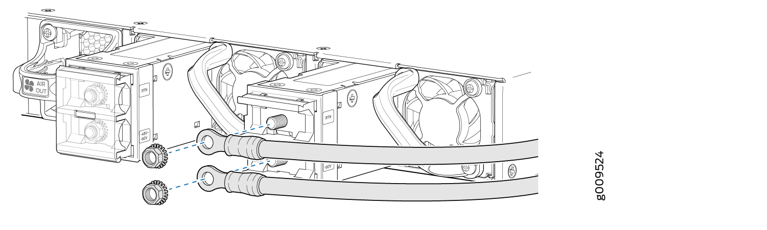
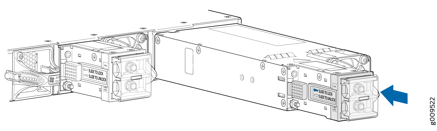
To install the DC power supply, see (Figure 5):
If you have a Juniper J-Care service contract, register any addition, change, or upgrade of hardware components at https://www.juniper.net/customers/support/tools/updateinstallbase/ . Failure to do so can result in significant delays if you need replacement parts. This note does not apply if you replace existing components with the same type of component.