Maintaining the SRX4600 Cooling System
Maintaining the Fan Modules on the SRX4600 Firewall
Purpose
For optimum cooling, verify the condition of the fan modules.
Action
Monitor the status of the fan modules. All the fan modules work in unison to cool the firewall. If one fan module fails, the redundant fan module acts as a backup. A major alarm is triggered when a fan fails, and a minor alarm and major alarm is triggered when a fan module is removed. We recommend that you replace the fan module immediately to maintain proper cooling.
To display the status of the cooling system, issue the
show chassis environmentcommand. The output shown below is an example.user@host> show chassis environment Class Item Status Measurement Routing Engine 0 CPU Testing Routing Engine 1 CPU Absent FPC 0 Exhaust Right Sensor OK 43 degrees C / 109 degrees F FPC 0 Glacis FPGA Die Temp OK 41 degrees C / 105 degrees F FPC 0 Intake Right Sensor OK 32 degrees C / 89 degrees F FPC 0 Intake left Sensor OK 31 degrees C / 87 degrees F FPC 0 Middle Sensor - 0 OK 36 degrees C / 96 degrees F FPC 0 Middle Sensor - 1 OK 36 degrees C / 96 degrees F FPC 0 Intake Sensor on Mezz board OK 27 degrees C / 80 degrees F FPC 0 CPU0 Die Temp Sensor OK 56 degrees C / 132 degrees F FPC 0 CPU1 Die Temp Sensor OK 78 degrees C / 172 degrees F FPC 1 Ambient Intake Sensor OK 26 degrees C / 78 degrees F FPC 1 XR1 Sensor OK 39 degrees C / 102 degrees F FPC 1 EA ASIC Sensor OK 48 degrees C / 118 degrees F FPC 1 Exhaust Sensor OK 40 degrees C / 104 degrees F FPC 1 Exhaust External Sensor OK 38 degrees C / 100 degrees F FPC 1 XR0 Sensor OK 36 degrees C / 96 degrees F Power Power Supply 0 OK 41 degrees C / 105 degrees F Power Supply 1 OK 36 degrees C / 96 degrees F Fans Fan Tray 0 Fan 0 OK Spinning at normal speed Fan Tray 0 Fan 1 OK Spinning at normal speed Fan Tray 1 Fan 0 OK Spinning at normal speed Fan Tray 1 Fan 1 OK Spinning at normal speed Fan Tray 2 Fan 0 OK Spinning at normal speed Fan Tray 2 Fan 1 OK Spinning at normal speed Fan Tray 3 Fan 0 OK Spinning at normal speed Fan Tray 3 Fan 1 OK Spinning at normal speed Fan Tray 4 Fan 0 OK Spinning at normal speed Fan Tray 4 Fan 1 OK Spinning at normal speed
The fan module numbers 0 to 4 are labeled on the sheet metal of firewall.
Replacing the SRX4600 Firewall Fan Module
Each fan module is a field-replaceable unit (FRU) installed in the rear panel of the SRX4600 Firewall. You can remove and replace the fan modules without powering off the firewall or disrupting firewall functions.
All the fan modules must be installed and operational for optimal functioning of the firewall.
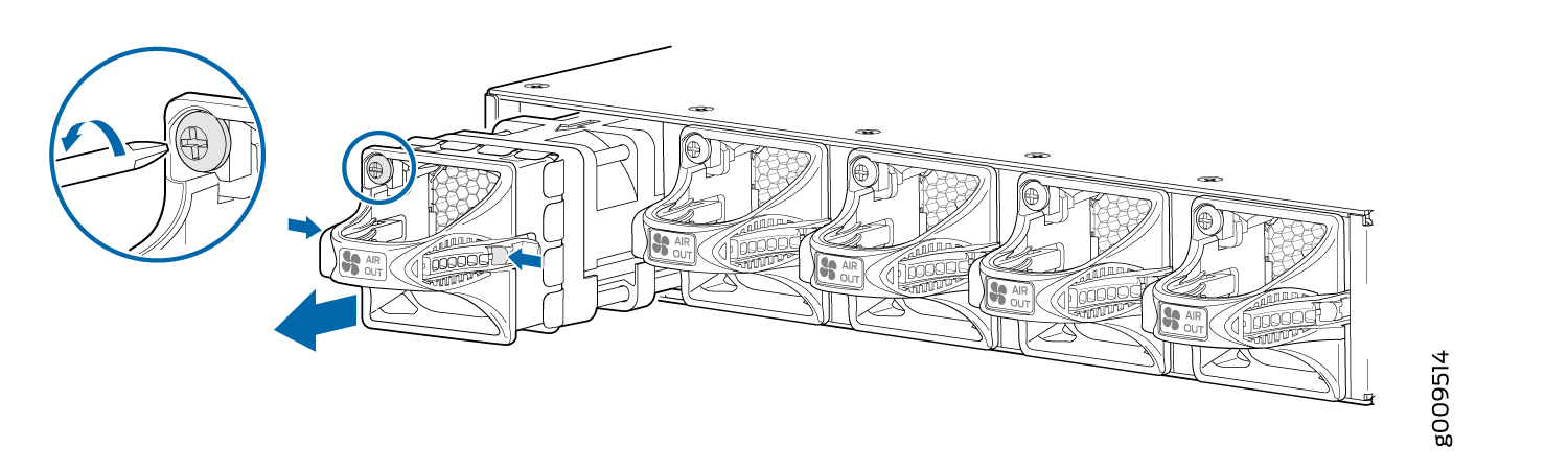
Removing the SRX4600 Firewall Fan Module
Ensure that you have the following tools and parts available:
-
Phillips (+) screwdriver, number 1
-
An antistatic bag or an antistatic mat
-
A replacement fan module
-
Electrostatic discharge (ESD) grounding strap
You can remove a fan module without powering off the firewall or disrupting firewall functions.
Once you remove the faulty fan module, make sure you install a working fan module within two minutes.
To remove the fan module (see Figure 1):
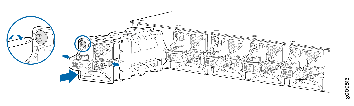
Installing the SRX4600 Firewall Fan Module
Ensure that you have the following tools and parts available:
-
ESD grounding strap
-
Phillips (+) screwdriver, number 1
You can install a fan module without powering off the firewall or disrupting firewall functions.
To install the fan module, see (Figure 2):
- Attach the ESD grounding strap to your bare wrist, and connect the strap to the ESD point on the chassis.
- Remove the fan module from its bag.
- Hold the handle of the fan module with one hand and support the weight of the module with the other hand. Place the fan module in the fan module slot on the rear panel of the firewall and slide it in until it is fully seated.
- Tighten the captive screws on the faceplate of the fan module by using the screwdriver.
If you have a Juniper J-Care service contract, register any addition, change, or upgrade of hardware components at https://www.juniper.net/customers/support/tools/updateinstallbase/ . Failure to do so can result in significant delays if you need replacement parts. This note does not apply if you replace existing components with the same type of component.