Use Juniper BNG CUPS Smart Session Load Balancing
This section describes how Juniper BNG CUPS uses smart session load balancing. This includes a description of the standards for broadband access network, a description of Juniper's BNG CUPS load balancing, and configuration requirements.
Juniper BNG CUPS Smart Session Load Balancing Overview
BNG CUPS smart session load balancing gives the operator the capability to distribute subscriber loads across the BNG User Planes in the network by moving subscribers from one BNG User Plane to another. Fast failover is a use case for subscriber session load balancing. The fast failover use case occurs when a BNG User Plane’s access port goes down and subscribers are rebalanced over to another access port on the same BNG User Plane.
BNG CUPS smart session load balancing, operates in accordance with the Broadband Forums TR 459 Multi-Service Disaggregated BNG with CUPS. Reference Architecture, Deployment Models, Interface, and Protocol specification. This smart session load balancing model takes into account the session load on a BNG User Plane and the throughput capacity used. It can be applied across different types of BNG User Planes, for any type of session access model (DHCP IPoE and PPPoE, single stack or double stack) and is controlled through the BNG CUPS controller. It assumes that there is Ethernet bridged access to the BNG User Planes, or an alternative like VPLS or EVPN. Smart session load balancing requires that the same residential gateway's first sign of life packet be received by multiple BNG User Planes. The first sign of life packets also, can be either DHCP Discover or PPPoE Active Discovery Initiation (PADI).
A BNG User Plane's subscriber limit should be configured for each linecard's PIC and it should be set to the specific linecard PFE maximum limit. This is because the maximum limit varies for each linecard PFE type. The subscribers limit for a PFE is used by resource monitoring to enforce resource consumption and thresholds on the PFE at different calls per second (CPS) rates. For DHCP access models, only 95% of the subscriber limit is supported.
You should not use the any option in the
accept stanza of the auto-configure
configuration. Instead, you should use the specific client protocol type in the
accept stanza (for example, DHCP, DHCPv6, PPPoE or a
combination of the protocol types).
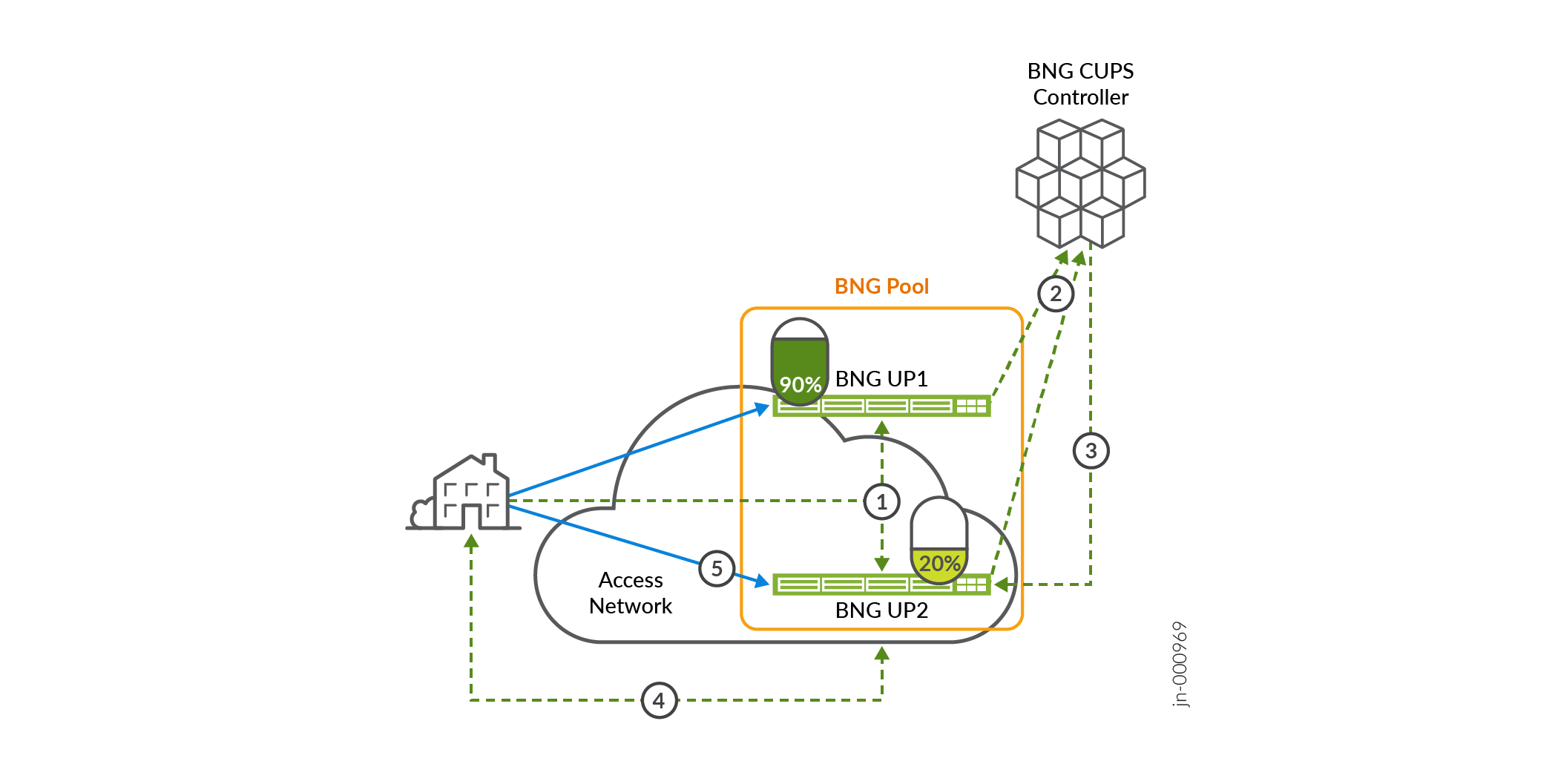
Figure 1 shows how BNG CUPS Controller implements subscriber load balancing.

Following is the work flow that Juniper BNG CUPS uses for subscriber load balancing (see Figure 1).
The subscriber session connects to the broadband access network. Both BNG User Planes (BNG-UP1 and BNG-UP2) in the shared BNG pool receive the broadcasted first sign of life request and forward it to the BNG CUPS Controller.
The BNG CUPS Controller receives the first sign of life requests from both BNG User Planes. Because BNG User Plane UP1 is currently loaded at 80%, the BNG CUPS Controller selects the less loaded BNG User Plane in the pool (BNG-UP2).
The BNG CUPS Controller replies to BNG User Plane BNG-UP2, letting it know that it is the anchor BNG User Plane for the subscriber.
BNG User Plane BNG-UP2 forwards the reply that it received from the BNG CUPS Controller to the subscriber’s residential gateway.
The subscriber’s traffic now flows through BNG User Plane BNG-UP2.
The BNG CUPS session load balancing model is based on the following two mutually exclusive criteria:
-
Load balancing at the BNG CUPS Controller is based on a live BNG User Plane reported load. The load is report as a percentage.
-
Weight is configured in the
dynamic-profileconfiguration on the BNG CUPS Controller. Weight can be either IFL-set weight or subscriber weight.
Report-based Subscriber Session Load Balancing
The BNG User Plane reported load balancing model assumes the following:
-
It uses a logical-port Packet Forwarding Control Protocol (PFCP) Information element (IE) as described in the TR-459 technical report.
-
It is dependent on the BNG User Plane sending the PFCP logical port usage reports to the BNG CUPS Controller.
-
It is done in-line in the control packet I/O processing, by allowing or denying the first sign of life packet when comparing the BNG User Plane logical port candidates. It chooses the BNG User Plane with the lowest usage (lowest percentage utilization). The logical port utilization for the logical port candidates is stored in the load balancing database.
The following configuration example shows a BNG User Plane reported load balancing configuration on the BNG CUPS Controller.
[edit groups bng-director bng-controller]
load-balancing-groups {
    lb-report-group {
        report-based-mode {
            port up:boston:xe-5/0/5:1;
            port up:nashua-c:xe-0/1/2;
            port up:manchester:xe-1/3/1;
       }
    }
}
On each BNG User Plane that is part of a report-based load balancing group, the
subscribers-limit configuration must be set for the line
card or the forwarding engine that the load balancing port is on.
[edit configuration system services resource-monitor]
subscribers-limit {
    client-type any {
        fpc 0 {
            limit 8500;
        }
    }
}
Weight-based Subscriber Session Load Balancing
Weight can be defined in different ways, based on your needs: Weight can be subscriber bandwidth, logical interface set bandwidth, or an even number of subscribers per logical interface set.
Weight-based load balancing can work with hierarchical class of service (HCoS) or independently.
Weight-based load balancing does not use the BNG User Plane logical port reported load. You can still examine the reported load from the BNG User Plane logical port. Use the show system subscriber load balancing group commands to examine the reported load.
When you configure weight-based load balancing, the BNG User Plane reported load is used only for monitoring purposes and troubleshooting.
Weight in the BNG CUPS Controller dynamic profile has the following characteristics:
-
It is dependent on the operator needs. It can be subscriber bandwidth, (subscriber or logical interface set) bandwidth, or the number of subscribers.
-
It compares the configured logical port maximum weight to the computed weight.
-
Computed weight is dynamic. It operates in the following ways:
-
It increases when each weighted item (subscriber or logical interface set) is instantiated.
-
It decreases when each weighted item (subscriber or logical interface set) is de-instantiated.
-
It compares the logical port configured maximum weight to allow or deny a subscriber on the logical port.
-
-
It works with hierarchical class of service (HCoS) and it can work independently.
-
It is part of the dynamic profile configuration. Weight based load balancing has a tolerance of one element above the maximum weight configured.
-
When load balancing weight is configured the BNG User Plane logical port reported load is ignored.
The following configuration example shows a weight based load balancing configuration on the BNG CUPS Controller.
[edit groups bng-director bng-controller]
load-balancing-groups {
   lb-weight-group {
      weight-based-mode {
         port up:boston:xe-5/0/5:1 {
            max-weight 10;
         }
         port up:nashua:xe-0/1/2 {
            max-weight 20;
         }
         port up:manchester:xe-1/3/1 {
             max-weight 30;
         }
      }
   }
}
Example: Configure Subscriber Session Load Balancing
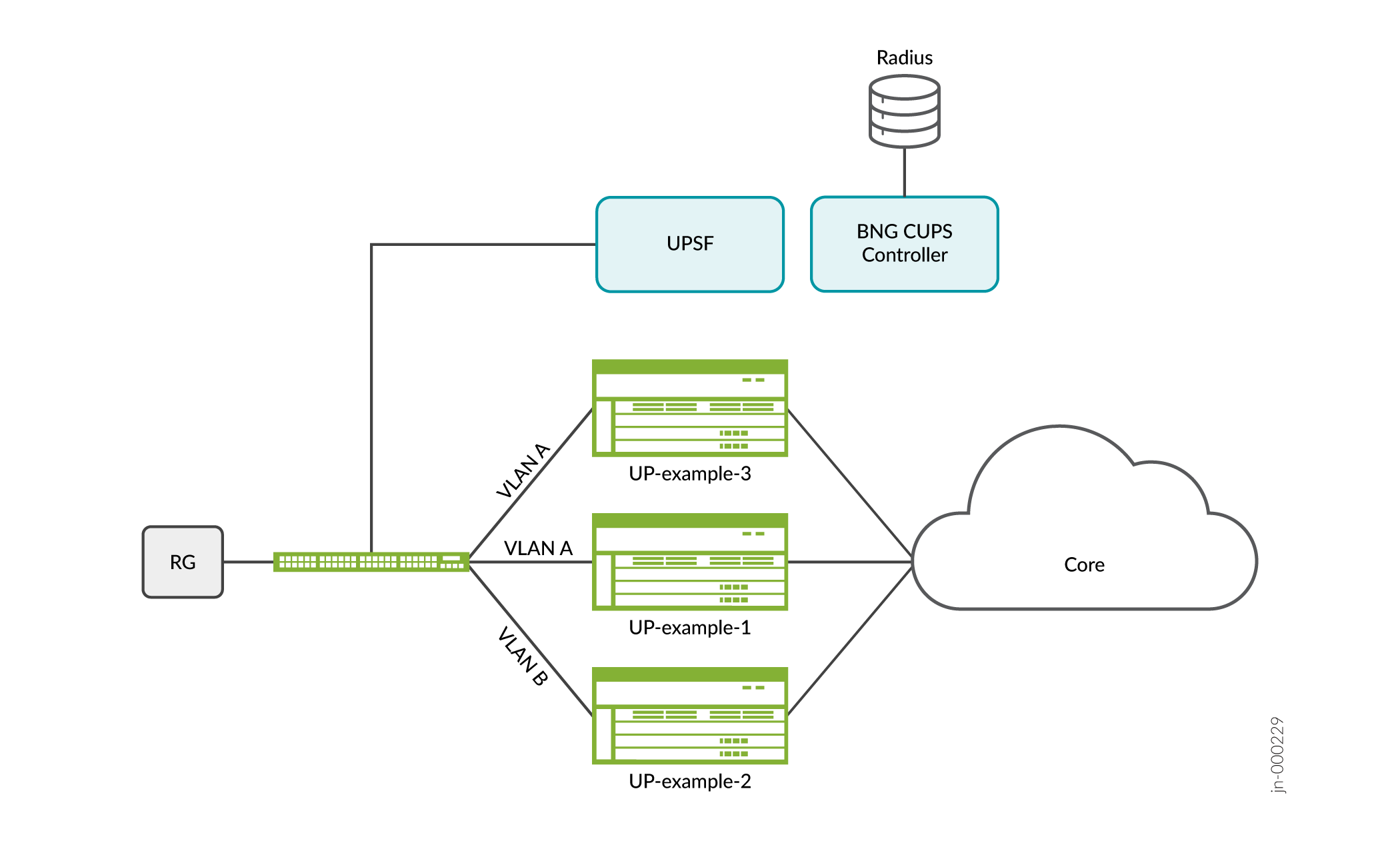
Consider the use case in Figure 2, where a BNG CUPS Controller manages two BNG User Planes (UP-example-1 and UP-example-3). They both can receive the same residential gateway’s PADI by being configured each with an active pseudowire that carry the same PADI to both BNG User Planes.

For weight-based load balancing, you use the dynamic profile configuration to specify subscriber weight or logical interface set weight.
To configure subscriber weight, perform the following configuration on the BNG CUPS Controller:
Report-based Load Balancing Operational Behavior
Consider the example of a PPPoE subscriber login using BNG User Plane load reports for load balancing. In this example, the same PADI that the residential gateway sends arrives at both BNG User Plane UP-example-1 and BNG User Plane UP-example-3.
Also, you define the load balancing group to contain UP-example-1 and UP-example-3 logical-ports to the pseudowires that carry the subscriber PADI.
[edit groups bng-director bng-controller]
user@host# set load-balancing-groups group-name user-plane UP-example-1 port UP-example-1:ps0.30
[edit groups bng-director bng-controller]
user@host# set load-balancing-groups group-name user-plane UP-example-3 port UP-example-3:ps0.25
Suppose that UP-example-1 exceeds an incremental threshold for which an upper limit exists, resulting in UP-example-1 reporting a load percentage that doesn’t allow any more subscribers.
As was mentioned earlier, the same PADI that the residential gateway sends arrives at both UP-example-1 and UP-example-3. Both UP-example-1 and UP-example-3 forward the PADI to the BNG CUPS Controller. The BNG CUPS Controller discards the UP-example-1 PADI and allow the PPPoE subscriber to log in to UP-example-3.
On each BNG User Plane that is part of a report-based load balancing group, the
subscribers-limit configuration must be set for the linecard or
the forwarding engine that the load balancing port is on. This limit must be higher
than the maximum number of subscribers expected.
For example, if the expected maximum is 8000, you set the
subscribers-limit to 8500.
[edit configuration system services resource-monitor]
subscribers-limit {
    client-type any {
        fpc 0 {
            limit 8500;
        }
    }
}
You can use the following load balancing show command to examine the
percentage load reported by the BNG User Planes for their logical ports.
user@host#> show load-balancing-group group lb-report
Logical-Port            % Usage     CPU Exceeded  Computed weight     Max weight
up:mx204-b:ae4            20          no             0                  0
up:mx204-i:xe-0/1/0       45          no             0                  0
up:mx204-b:ae4            10          no             0                  0
Weight-based Load Balancing Operational Behavior
Consider the example of a PPPoE subscriber login using BNG User Plane load reports for load balancing. In this example, the same PADI that the residential gateway sends arrives at both BNG User Plane UP-example-1 and BNG User Plane UP-example-3.
Consider the example of a PPPoE subscriber login using weight for load balancing. In this example, the PADI that the residential gateway sends arrives at both BNG User Plane UP-example-1 and BNG User Plane UP-example-3.
In this example, you configure the logical-port maximum weight on the BNG CUPS Controller. Define the load-balancing group to contain UP-example-1 and UP-example-3 logical-ports.
[edit groups bng-director bng-controller]
user@host# set load-balancing-groups group-name user-plane UP-example-1 port UP-example-1:ps0.30 max-weight 10
[edit groups bng-director bng-controller]
user@host# set load-balancing-groups group-name user-plane UP-example-3 port UP-example-3:ps0.25 max-weight 10
After you configure the weight, you then configure the logical interface set in the dynamic profile.
[edit]
user@host# set dynamic-profiles profile-name interfaces interface-set interface-set-name load-balance weight 2.5
The first PPPoE subscriber that logs in creates the logical interface set on BNG User Plane UP-example-1. Each logical interface set weight is added up to a computed weight that must be less than 10 (the max logical port weight).
After the subscriber's log in creates the logical interface set and places the logical interface set on a BNG User Plane, it doesn’t move. All subscribers belonging to that logical interface set follow the logical interface set (placed on the same BNG User Plane as their corresponding logical interface set).
After that, every new PADI coming in for this logical interface set is placed on BNG User Plane UP-example-1 and dropped from BNG User Plane UP-example-3.
As subscribers for a new logical interface set login, the new logical interface set weight is added to the computed weight and compared to the maximum weight. When the computed weight is greater than the maximum weight, the new logical interface set is no longer placed on BNG User Plane UP-example-1. Instead, the logical interface set is placed on BNG User Plane UP-example-3.
