BNG Redundancy for DHCP Subscribers Using Packet Triggered Based Recovery
Learn about broadband network gateway (BNG) redundancy using packet triggered based recovery which provides simple, easy to use, and lightweight stateless subscriber redundancy.
BNG Redundancy for DHCP Subscribers Using Packet Triggered Based Recovery Overview
The BNG redundancy for DHCP subscribers using packet triggered based recovery provides simple, easy to use, and lightweight stateless redundancy with minimal traffic loss. The stateless BNG redundancy for DHCP subscribers supports dynamic C-VLAN and static VLAN model for both relay and server. The packet triggered based recovery utilizes the existing features such as auto configuration of VLAN and packet triggered subscribers.
- Auto Configuration of VLAN
- Packet Triggered Subscribers
- Benefits of BNG Redundancy for DHCP Subscribers Using Packet Triggered Based Recovery
Auto Configuration of VLAN
The auto configuration feature creates dynamic VLAN (DVLAN) logical interface on receiving the first VLAN packet from the client. On receiving the first packet, the Routing Engine authenticates the subscriber with authenticating server. The authentication server might need the accounting and advanced services details for authenticating the subscriber. The Routing Engine creates the DVLAN logical interface based on the request from the authenticating server. After creating the DVLAN logical interface, the system forwards the packet to the protocol stack for further processing.
Packet Triggered Subscribers
The packet-triggered subscriber feature creates IP demux logical interface on receiving a packet from clients with the pre-assigned IPv4 or IPv6 address. The forwarding plane validates the source IP address and matches with the configured IP address or prefix ranges. After the source IP address validation, the forwarding plane forwards the packet to the Routing Engine. The Routing Engine authenticates the subscriber with authenticating server as per the volume of accounting and advanced services such as firewall filter and CoS. Routing Engine creates IP demux logical interface as per the services requested by the authenticating server.
Benefits of BNG Redundancy for DHCP Subscribers Using Packet Triggered Based Recovery
- Provides simple backup BNG deployment.
How BNG Redundancy for DHCP Subscribers Using Packet Triggered Based Recovery Works
Primary BNG hosts the subscribers during normal traffic flow. When the traffic flow fails in the primary BNG, the access nodes redirect the traffic to the backup BNG. The primary BNG can fail due to following reasons:
- Intermediate node failure or link failure which breaks the MPLS path between access node and primary BNG.
- Primary BNG link or port failure.
- Primary BNG line card failure.
- Primary BNG Routing Engine failure.
- Primary BNG chassis failure.
- Primary BNG to core network link failure.
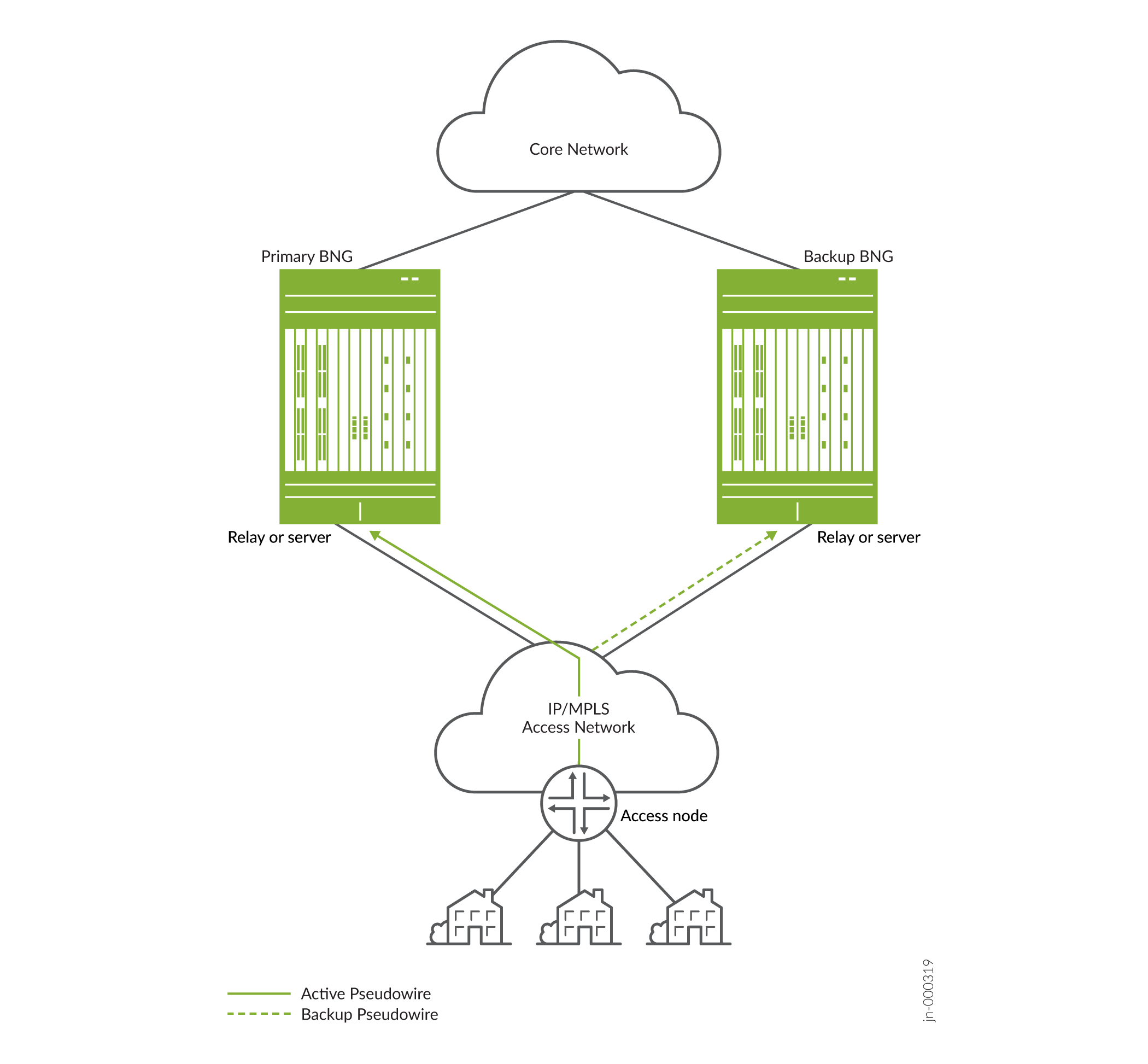
Figure 1 shows the topology diagram for layer 2 circuit based on IP/MPLS pseudowire headend termination (PWHT) scenario.
Based on the first traffic after failover, the Routing Engine creates DVLAN and dynamic IP subscriber. Packet Forwarding Engine forwards the subsequent traffic in the forwarding plane to the core router as per QoS and services attached to the IP subscriber. This QoS and the services are not the same QoS and services of the subscriber created in the Primary BNG. These are the common default dynamic IP subscriber profile features, assigned by RADIUS server or local configuration, until the session lease renewal and re-authentication occurs.
Once the system creates the DHCP subscriber in the secondary BNG, it provides limited QoS and other services at best-effort traffic with minimal interruption. When the DHCP client lease timer expires, it tries to re-negotiate lease time and a new DHCP protocol exchange takes place. This time, the system creates the fully functional DHCP subscriber along with QoS and advanced services as that of the primary BNG. The Packet Forwarding Engine forwards the traffic also to the core router accordingly. The system deletes the dynamic IP subscriber when the fully functional DHCP subscriber is active.
The traffic switchover to the backup BNG and the revert to the primary BNG process is similar. If revert occurs after the first lease timeout, the system proceeds with the switchover process. If revert occurs before the first lease timeout, the system proceeds with revert as it still has the previously assigned IP address and DHCP bindings.
The BNG redundancy using packet triggered based recovery feature supports the following access network topology for BNG redundancy:
- Layer 2 VPN scenario
- Layer 2 circuit based on IP/MPLS PWHT scenario
- Ethernet VPN–virtual private wireless service (EVPN-VPWS).
Configuring BNG Redundancy Using Packet Triggered Recovery for DHCP Subscribers
Overview
Starting from 22.4R1, Junos supports Broadband Network Gateway (BNG) redundancy configuration using packet-trigger based recovery that provides easy to use and lightweight stateless subscriber redundancy.
This section provides a configuration example for packet triggered BNG redundancy for DHCP subscribers using a local DHCP server.
Requirements
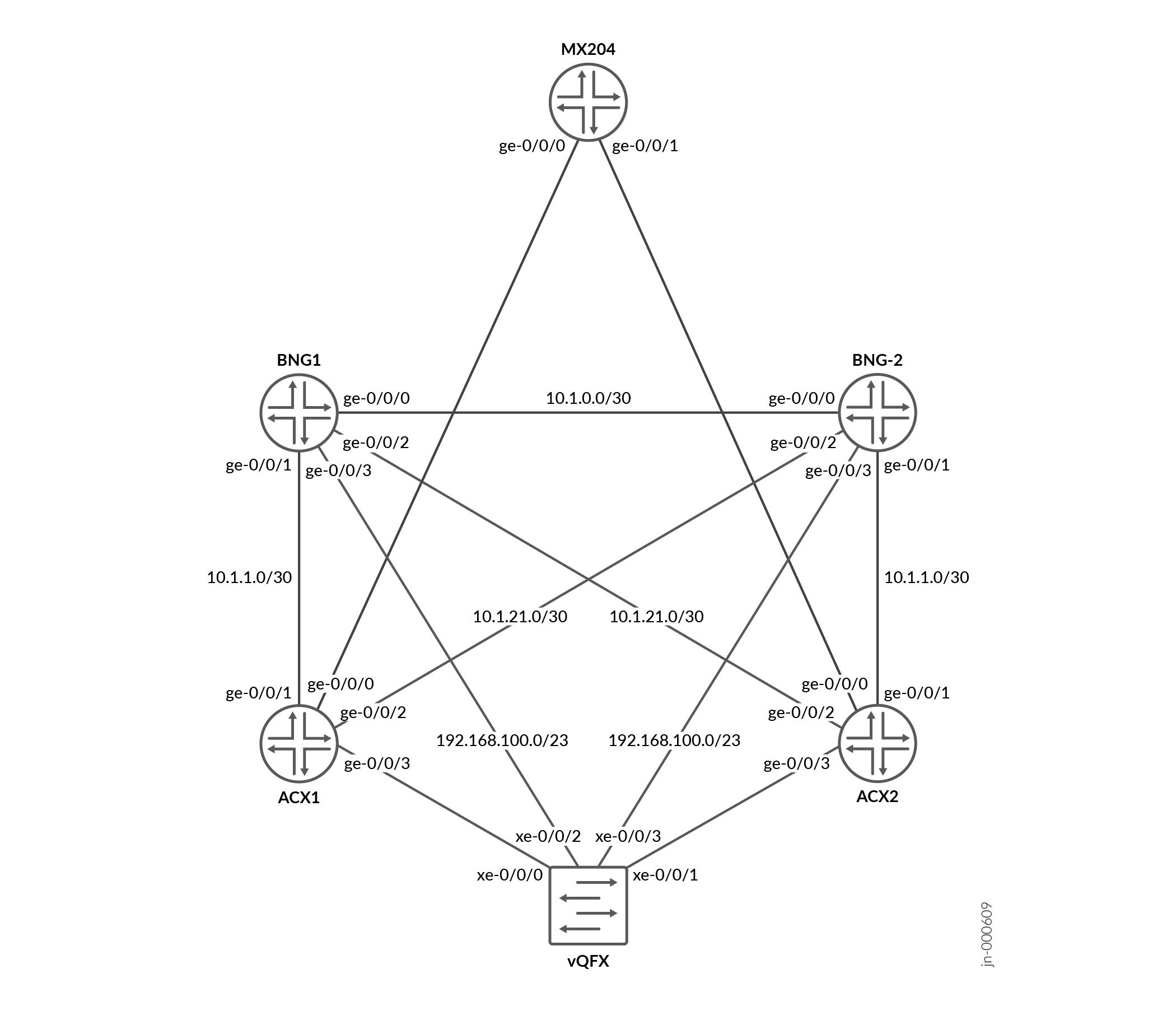
The configuration example uses the following devices:
- BNG1 and BNG2 broadband network gateways run EVPN-VPWS pseudowire headend termination (PWHT) with the ACX aggregation nodes and terminate the IPoE sessions. The BNG implements the packet triggered redundancy for the IPoE sessions.
- ACX1 and ACX2 devices aggregate the Access Nodes traffic through the Cloud Metro Fabric towards the BNGs.
- MX204 device is used for simulated peripheral connectivity.
- vQFX instance for Q-in-Q tunneling and VLAN translation.
Topology
Figure 2 shows the physical topology with two vMX devices configured as BNG1 and BNG2 servers, two access devices ACX1 and ACX2, a vQFX and an MX204 device.
Configuration
- CLI Quick Configuration
- Device BNG1
- Device BNG2
- Device ACX1
- Device ACX2
- Step-by-Step Procedure
- Configuring BNG1
- Configuring BNG2
- Configuring ACX1
- Configuring ACX2
CLI Quick Configuration
Device BNG1
To quickly configure this example, copy the following commands, paste them into a text file, remove any line breaks, change any details necessary to match your network configuration, and then copy and paste the commands into the CLI at the [edit] hierarchy level.
set system host-name BNG1
set system configuration-database max-db-size 698343424
set system services ssh root-login allow
set chassis network-services enhanced-ip
set groups GR-CORE-INTF interfaces <*> description ********GR-CORE-INTF-SETTINGS-APPLIED ********
set groups GR-CORE-INTF interfaces <*> traps
set groups GR-CORE-INTF interfaces <*> mtu 9192
set groups GR-CORE-INTF interfaces <*> hold-time up 2000
set groups GR-CORE-INTF interfaces <*> hold-time down 0
set groups GR-CORE-INTF interfaces <*> damping half-life 30
set groups GR-CORE-INTF interfaces <*> damping max-suppress 600
set groups GR-CORE-INTF interfaces <*> damping reuse 250
set groups GR-CORE-INTF interfaces <*> damping suppress 2000
set groups GR-CORE-INTF interfaces <*> damping enable
set groups GR-CORE-INTF interfaces <*> unit 0 traps
set groups GR-CORE-INTF interfaces <*> unit 0 family inet mtu 9106
set groups GR-CORE-INTF interfaces <*> unit 0 family iso mtu 9106
set groups GR-CORE-INTF interfaces <*> unit 0 family mpls mtu 9170
set groups GR-CORE-INTF interfaces <*> unit 0 family mpls maximum-labels 5
set interfaces ge-0/0/0 apply-groups GR-CORE-INTF
set interfaces ge-0/0/0 unit 0 family inet address 10.1.0.1/30
set interfaces ge-0/0/0 unit 0 family iso
set interfaces ge-0/0/0 unit 0 family mpls
set interfaces ge-0/0/1 apply-groups GR-CORE-INTF
set interfaces ge-0/0/1 unit 0 family inet address 10.1.1.1/30
set interfaces ge-0/0/1 unit 0 family iso
set interfaces ge-0/0/1 unit 0 family mpls
set interfaces ge-0/0/2 apply-groups GR-CORE-INTF
set interfaces ge-0/0/2 unit 0 family inet address 10.1.21.2/30
set interfaces ge-0/0/2 unit 0 family iso
set interfaces ge-0/0/2 unit 0 family mpls
set interfaces ge-0/0/3 mtu 9192
set interfaces ge-0/0/3 unit 0 family inet address 192.168.100.171/23
set interfaces lo0 unit 0 family inet address 172.31.100.3/32
set interfaces lo0 unit 0 family inet address 192.168.0.1/32 primary
set interfaces lo0 unit 0 family inet address 192.168.0.1/32 preferred
set interfaces lo0 unit 0 family iso address 49.0001.1000.0000.0003.00
set interfaces lo0 unit 0 family mpls
set protocols isis interface ge-0/0/0.0
set protocols isis interface ge-0/0/1.0
set protocols isis interface ge-0/0/2.0
set protocols isis interface lo0.0 passive
set protocols isis level 1 disable
set policy-options policy-statement PL-ISIS-EXPORT term LOCAL-LOOPBACK from protocol direct
set policy-options policy-statement PL-ISIS-EXPORT term LOCAL-LOOPBACK from interface lo0.0
set policy-options policy-statement PL-ISIS-EXPORT term LOCAL-LOOPBACK from route-filter 172.31.0.0/16 prefix-length-range /32-/32
set policy-options policy-statement PL-ISIS-EXPORT term LOCAL-LOOPBACK then tag 101
set policy-options policy-statement PL-ISIS-EXPORT term LOCAL-LOOPBACK then accept
set policy-options policy-statement PL-ISIS-EXPORT term DIRECT-ROUTES from protocol direct
set policy-options policy-statement PL-ISIS-EXPORT term DIRECT-ROUTES then accept
set policy-options policy-statement PL-ISIS-EXPORT then reject
set protocols isis export PL-ISIS-EXPORT
set routing-options router-id 172.31.100.3
set routing-options autonomous-system 65000
set protocols bgp group IBGP type internal
set protocols bgp group IBGP local-address 172.31.100.3
set protocols bgp group IBGP family evpn signaling
set protocols bgp group IBGP cluster 1.1.1.1
set protocols bgp group IBGP neighbor 172.31.100.4
set protocols bgp group IBGP neighbor 172.31.100.11
set protocols bgp group IBGP neighbor 172.31.100.12
set protocols ldp deaggregate
set protocols ldp transport-address 172.31.100.3
set protocols ldp interface all
set protocols mpls interface all
set system services subscriber-management traceoptions file submgmt.log
set system services subscriber-management traceoptions file size 30m
set system services subscriber-management traceoptions file files 10
set system services subscriber-management traceoptions flag all
set system services subscriber-management gres-route-flush-delay
set system services subscriber-management enable
set system processes general-authentication-service traceoptions file authd
set system processes general-authentication-service traceoptions file size 10m
set system processes general-authentication-service traceoptions file files 10
set system processes general-authentication-service traceoptions flag all
set system processes smg-service traceoptions file smgd
set system processes smg-service traceoptions file size 10m
set system processes smg-service traceoptions file files 10
set system processes smg-service traceoptions level all
set system processes smg-service traceoptions flag all
set system processes dhcp-service traceoptions file jdhcpd
set system processes dhcp-service traceoptions file size 10m
set system processes dhcp-service traceoptions file files 10
set system processes dhcp-service traceoptions level all
set system processes dhcp-service traceoptions flag packet
set system processes dhcp-service traceoptions flag all
set chassis fpc 0 pic 0 tunnel-services bandwidth 1g
set chassis fpc 0 performance-mode
set access-profile no-auth
set access profile no-auth authentication-order none
set access address-protection
set chassis pseudowire-service device-count 10
set interfaces ps0 anchor-point lt-0/0/10
set interfaces ps0 flexible-vlan-tagging
set interfaces ps0 auto-configure stacked-vlan-ranges authentication username-include delimiter "@"
set interfaces ps0 auto-configure stacked-vlan-ranges authentication username-include user-prefix vlan
set interfaces ps0 auto-configure stacked-vlan-ranges authentication username-include interface-name
set interfaces ps0 auto-configure stacked-vlan-ranges access-profile no-auth
set interfaces ps0 auto-configure remove-when-no-subscribers
set interfaces ps0 mtu 2022
set interfaces ps0 esi 00:10:00:00:01:00:00:00:10:00
set interfaces ps0 esi single-active
set interfaces ps0 esi df-election-type preference value 1000
set interfaces ps0 unit 0 encapsulation ethernet-ccc
set interfaces lo0 unit 20 description "VRF:internet Loopback"
set interfaces lo0 unit 20 family inet address 172.16.100.3/32 primary
set routing-instances internet instance-type vrf
set routing-instances internet routing-options auto-export
set routing-instances internet interface lo0.20
set routing-instances internet route-distinguisher 172.31.100.3:12
set routing-instances internet vrf-import internet-vrf-import-pol
set routing-instances internet vrf-export internet-vrf-export-pol
set routing-instances internet vrf-table-label
set policy-options policy-statement internet-vrf-export-pol term all then community add 65000:999
set policy-options policy-statement internet-vrf-export-pol term all then accept
set policy-options policy-statement internet-vrf-import-pol term default from community 65000:999
set policy-options policy-statement internet-vrf-import-pol term default then accept
set policy-options policy-statement internet-vrf-import-pol term subs from community 65000:1131
set policy-options policy-statement internet-vrf-import-pol term subs then accept
set policy-options policy-statement internet-vrf-import-pol term other from community 65000:113
set policy-options policy-statement internet-vrf-import-pol term other then accept
set policy-options community 65000:113 members target:65000:113
set policy-options community 65000:1131 members target:65000:1131
set policy-options community 65000:999 members target:65000:999
set interfaces lo0 unit 313 description "VRF:dhcp-subs Loopback"
set interfaces lo0 unit 313 family inet address 172.16.16.3/32
set interfaces lo0 unit 313 family inet address 10.42.0.1/32 primary
set interfaces lo0 unit 313 family inet6 address 2015:cafe:2000::1/128
set routing-instances dhcp-subs instance-type vrf
set routing-instances dhcp-subs routing-options rib dhcp-subs.inet6.0 static route ::/0 next-table internet.inet6.0
set routing-instances dhcp-subs routing-options rib dhcp-subs.inet6.0 static route ::/0 no-readvertise
set routing-instances dhcp-subs routing-options router-id 172.16.16.3
set routing-instances dhcp-subs routing-options flow term-order standard
set routing-instances dhcp-subs routing-options static route 0.0.0.0/0 next-table internet.inet.0
set routing-instances dhcp-subs routing-options static route 0.0.0.0/0 no-readvertise
set routing-instances dhcp-subs routing-options static route 10.42.0.0/16 discard
set routing-instances dhcp-subs routing-options static route 10.42.0.0/16 tag 200
set routing-instances dhcp-subs routing-options auto-export
set routing-instances dhcp-subs system services dhcp-local-server group dhcp-ls liveness-detection failure-action clear-binding-if-interface-up
set routing-instances dhcp-subs system services dhcp-local-server group dhcp-ls liveness-detection method bfd version automatic
set routing-instances dhcp-subs system services dhcp-local-server group dhcp-ls liveness-detection method bfd minimum-interval 30000
set routing-instances dhcp-subs system services dhcp-local-server group dhcp-ls liveness-detection method bfd multiplier 3
set routing-instances dhcp-subs system services dhcp-local-server group dhcp-ls overrides client-discover-match incoming-interface
set routing-instances dhcp-subs system services dhcp-local-server group dhcp-ls overrides dual-stack dhcp-ds
set routing-instances dhcp-subs system services dhcp-local-server group dhcp-ls interface demux0.0
set routing-instances dhcp-subs system services dhcp-local-server group dhcp-ls interface ps0.0
set routing-instances dhcp-subs system services dhcp-local-server dual-stack-group dhcp-ds authentication username-include mac-address
set routing-instances dhcp-subs system services dhcp-local-server dual-stack-group dhcp-ds on-demand-address-allocation
set routing-instances dhcp-subs system services dhcp-local-server dual-stack-group dhcp-ds classification-key mac-address
set routing-instances dhcp-subs system services dhcp-local-server dual-stack-group dhcp-ds protocol-master inet
set routing-instances dhcp-subs system services dhcp-local-server no-stale-timer-refresh
set routing-instances dhcp-subs system services dhcp-local-server stale-timer 60
set routing-instances dhcp-subs access address-assignment high-utilization 80
set routing-instances dhcp-subs access address-assignment abated-utilization 70
set routing-instances dhcp-subs access address-assignment pool ttt-fttx-res-ipv4-pool-0 family inet network 10.42.0.0/16
set routing-instances dhcp-subs access address-assignment pool ttt-fttx-res-ipv4-pool-0 family inet range range1 low 10.42.0.2
set routing-instances dhcp-subs access address-assignment pool ttt-fttx-res-ipv4-pool-0 family inet range range1 high 10.42.255.254
set routing-instances dhcp-subs access address-assignment pool ttt-fttx-res-ipv4-pool-0 family inet dhcp-attributes maximum-lease-time 600
set routing-instances dhcp-subs access address-assignment pool ttt-fttx-res-ipv4-pool-0 family inet dhcp-attributes server-identifier 10.42.0.1
set routing-instances dhcp-subs access address-assignment pool ttt-fttx-res-ipv4-pool-0 family inet dhcp-attributes router 10.42.0.1
set routing-instances dhcp-subs access-profile no-auth
set routing-instances dhcp-subs interface lo0.313
set routing-instances dhcp-subs route-distinguisher 172.31.100.3:13
set routing-instances dhcp-subs vrf-import dhcp-subs-vrf-import-pol
set routing-instances dhcp-subs vrf-export dhcp-subs-vrf-export-pol
set routing-instances dhcp-subs vrf-table-label
set policy-options policy-statement dhcp-subs-vrf-export-pol term loop from protocol direct
set policy-options policy-statement dhcp-subs-vrf-export-pol term loop from route-filter 172.16.16.3/32 exact
set policy-options policy-statement dhcp-subs-vrf-export-pol term loop then community add 65000:113
set policy-options policy-statement dhcp-subs-vrf-export-pol term pools from protocol static
set policy-options policy-statement dhcp-subs-vrf-export-pol term pools from tag 200
set policy-options policy-statement dhcp-subs-vrf-export-pol term pools then community add 65000:113
set policy-options policy-statement dhcp-subs-vrf-export-pol term subs then community add 65000:1131
set policy-options policy-statement dhcp-subs-vrf-export-pol term subs then accept
set policy-options policy-statement dhcp-subs-vrf-import-pol term all from community 65000:111
set policy-options policy-statement dhcp-subs-vrf-import-pol term all then accept
set policy-options community 65000:111 members target:65000:111
set policy-options community 65000:111 members target:65000:11
set access domain map none access-profile no-auth
set access domain map none target-routing-instance dhcp-subs
set access domain map ps0.* access-profile no-auth
set access domain map ps0.* target-routing-instance dhcp-subs
set access domain map ps0:* access-profile no-auth
set access domain map ps0:* target-routing-instance dhcp-subs
set firewall family inet filter rpf-pass-dhcp term allow-dhcp from destination-address 255.255.255.255/32
set firewall family inet filter rpf-pass-dhcp term allow-dhcp from destination-port dhcp
set firewall family inet filter rpf-pass-dhcp term allow-dhcp then accept
set firewall family inet filter rpf-pass-dhcp term default then discard
set system dynamic-profile-options versioning
set dynamic-profiles prod-dhcp-base routing-instances "$junos-routing-instance" interface "$junos-interface-name"
set dynamic-profiles prod-dhcp-base routing-instances "$junos-routing-instance" routing-options access route $junos-framed-route-ip-address-prefix metric "$junos-framed-route-cost"
set dynamic-profiles prod-dhcp-base interfaces demux0 unit "$junos-interface-unit" actual-transit-statistics
set dynamic-profiles prod-dhcp-base interfaces demux0 unit "$junos-interface-unit" demux-options underlying-interface "$junos-underlying-interface"
set dynamic-profiles prod-dhcp-base interfaces demux0 unit "$junos-interface-unit" family inet rpf-check fail-filter rpf-pass-dhcp
set dynamic-profiles prod-dhcp-base interfaces demux0 unit "$junos-interface-unit" family inet demux-source $junos-subscriber-ip-address
set dynamic-profiles prod-dhcp-base interfaces demux0 unit "$junos-interface-unit" family inet unnumbered-address lo0.313
set dynamic-profiles prod-dhcp-base interfaces demux0 unit "$junos-interface-unit" family inet6 demux-source $junos-subscriber-ipv6-address
set dynamic-profiles prod-dhcp-base interfaces demux0 unit "$junos-interface-unit" family inet6 unnumbered-address lo0.313
set routing-instances dhcp-subs system services dhcp-local-server dual-stack-group dhcp-ds dynamic-profile prod-dhcp-base
set dynamic-profiles auto-pwht routing-instances "$junos-routing-instance" interface "$junos-interface-name"
set dynamic-profiles auto-pwht routing-instances "$junos-routing-instance" routing-options access route $junos-framed-route-ip-address-prefix next-hop "$junos-framed-route-nexthop"
set dynamic-profiles auto-pwht routing-instances "$junos-routing-instance" routing-options access route $junos-framed-route-ip-address-prefix metric "$junos-framed-route-cost"
set dynamic-profiles auto-pwht interfaces interface-set "$junos-phy-ifd-interface-set-name" interface "$junos-interface-ifd-name" unit "$junos-interface-unit"
set dynamic-profiles auto-pwht interfaces "$junos-interface-ifd-name" unit "$junos-interface-unit" no-traps
set dynamic-profiles auto-pwht interfaces "$junos-interface-ifd-name" unit "$junos-interface-unit" proxy-arp restricted
set dynamic-profiles auto-pwht interfaces "$junos-interface-ifd-name" unit "$junos-interface-unit" vlan-id "$junos-vlan-id"
set dynamic-profiles auto-pwht interfaces "$junos-interface-ifd-name" unit "$junos-interface-unit" family inet mac-validate loose
set dynamic-profiles auto-pwht interfaces "$junos-interface-ifd-name" unit "$junos-interface-unit" family inet unnumbered-address "$junos-loopback-interface"
set dynamic-profiles auto-stacked-pwht routing-instances "$junos-routing-instance" interface "$junos-interface-name"
set dynamic-profiles auto-stacked-pwht interfaces "$junos-interface-ifd-name" unit "$junos-interface-unit" no-traps
set dynamic-profiles auto-stacked-pwht interfaces "$junos-interface-ifd-name" unit "$junos-interface-unit" proxy-arp
set dynamic-profiles auto-stacked-pwht interfaces "$junos-interface-ifd-name" unit "$junos-interface-unit" vlan-tags outer "$junos-stacked-vlan-id"
set dynamic-profiles auto-stacked-pwht interfaces "$junos-interface-ifd-name" unit "$junos-interface-unit" vlan-tags inner "$junos-vlan-id"
set dynamic-profiles auto-stacked-pwht interfaces "$junos-interface-ifd-name" unit "$junos-interface-unit" demux-options underlying-interface "$junos-interface-ifd-name"
set dynamic-profiles auto-stacked-pwht interfaces "$junos-interface-ifd-name" unit "$junos-interface-unit" family inet mac-validate strict
set dynamic-profiles auto-stacked-pwht interfaces "$junos-interface-ifd-name" unit "$junos-interface-unit" family inet unnumbered-address "$junos-loopback-interface"
set dynamic-profiles auto-stacked-pwht interfaces "$junos-interface-ifd-name" unit "$junos-interface-unit" family inet auto-configure address-ranges dynamic-profile PROF_AUTOSENSE_IPDEMUX network 10.42.0.0/16
set dynamic-profiles auto-stacked-pwht interfaces "$junos-interface-ifd-name" unit "$junos-interface-unit" family inet auto-configure address-ranges dynamic-profile PROF_AUTOSENSE_IPDEMUX network 10.43.0.0/16
set dynamic-profiles auto-stacked-pwht interfaces "$junos-interface-ifd-name" unit "$junos-interface-unit" family inet auto-configure address-ranges authentication username-include delimiter "@"
set dynamic-profiles auto-stacked-pwht interfaces "$junos-interface-ifd-name" unit "$junos-interface-unit" family inet auto-configure address-ranges authentication username-include user-prefix vlan
set dynamic-profiles auto-stacked-pwht interfaces "$junos-interface-ifd-name" unit "$junos-interface-unit" family inet auto-configure address-ranges authentication username-include interface-name
set dynamic-profiles auto-stacked-pwht interfaces "$junos-interface-ifd-name" unit "$junos-interface-unit" family inet auto-configure address-ranges session-timeout 600
set dynamic-profiles PROF_AUTOSENSE_IPDEMUX routing-instances "$junos-routing-instance" interface "$junos-interface-name"
set dynamic-profiles PROF_AUTOSENSE_IPDEMUX interfaces demux0 unit "$junos-underlying-interface-unit" family inet mac-validate strict
set dynamic-profiles PROF_AUTOSENSE_IPDEMUX interfaces demux0 unit "$junos-underlying-interface-unit" family inet unnumbered-address lo0.313
set dynamic-profiles PROF_AUTOSENSE_IPDEMUX interfaces demux0 unit "$junos-underlying-interface-unit" family inet6 unnumbered-address lo0.313
set interfaces ps0 auto-configure stacked-vlan-ranges dynamic-profile auto-stacked-pwht accept any
set interfaces ps0 auto-configure stacked-vlan-ranges dynamic-profile auto-stacked-pwht ranges any,any
set interfaces ps0 auto-configure vlan-ranges dynamic-profile auto-pwht accept any
set interfaces ps0 auto-configure vlan-ranges dynamic-profile auto-pwht ranges any
set routing-instances EVPN-VPWS-BNG-1 instance-type evpn-vpws
set routing-instances EVPN-VPWS-BNG-1 protocols evpn interface ps0.0 vpws-service-id local 9999
set routing-instances EVPN-VPWS-BNG-1 protocols evpn interface ps0.0 vpws-service-id remote 1111
set routing-instances EVPN-VPWS-BNG-1 interface ps0.0
set routing-instances EVPN-VPWS-BNG-1 route-distinguisher 172.31.100.3:11
set routing-instances EVPN-VPWS-BNG-1 vrf-target target:65000:11
Device BNG2
set system host-name BNG2
set system configuration-database max-db-size 698343424
set system services ssh root-login allow
set chassis network-services enhanced-ip
set groups GR-CORE-INTF interfaces <*> description ********GR-CORE-INTF-SETTINGS-APPLIED-ADD-DESCRIPTION********
set groups GR-CORE-INTF interfaces <*> traps
set groups GR-CORE-INTF interfaces <*> mtu 9192
set groups GR-CORE-INTF interfaces <*> hold-time up 2000
set groups GR-CORE-INTF interfaces <*> hold-time down 0
set groups GR-CORE-INTF interfaces <*> damping half-life 30
set groups GR-CORE-INTF interfaces <*> damping max-suppress 600
set groups GR-CORE-INTF interfaces <*> damping reuse 250
set groups GR-CORE-INTF interfaces <*> damping suppress 2000
set groups GR-CORE-INTF interfaces <*> damping enable
set groups GR-CORE-INTF interfaces <*> unit 0 traps
set groups GR-CORE-INTF interfaces <*> unit 0 family inet mtu 9106
set groups GR-CORE-INTF interfaces <*> unit 0 family iso mtu 9106
set groups GR-CORE-INTF interfaces <*> unit 0 family mpls mtu 9170
set groups GR-CORE-INTF interfaces <*> unit 0 family mpls maximum-labels 5
set interfaces ge-0/0/0 apply-groups GR-CORE-INTF
set interfaces ge-0/0/0 unit 0 family inet address 10.1.0.2/30
set interfaces ge-0/0/0 unit 0 family iso
set interfaces ge-0/0/0 unit 0 family mpls
set interfaces ge-0/0/1 apply-groups GR-CORE-INTF
set interfaces ge-0/0/1 unit 0 family inet address 10.1.2.2/30
set interfaces ge-0/0/1 unit 0 family iso
set interfaces ge-0/0/1 unit 0 family mpls
set interfaces ge-0/0/2 apply-groups GR-CORE-INTF
set interfaces ge-0/0/2 unit 0 family inet address 10.1.12.2/30
set interfaces ge-0/0/2 unit 0 family iso
set interfaces ge-0/0/2 unit 0 family mpls
set interfaces ge-0/0/3 mtu 9192
set interfaces ge-0/0/3 unit 0 family inet address 192.168.100.171/23
set interfaces lo0 unit 0 family inet address 172.31.100.4/32
set interfaces lo0 unit 0 family inet address 192.168.0.1/32 primary
set interfaces lo0 unit 0 family inet address 192.168.0.1/32 preferred
set interfaces lo0 unit 0 family iso address 49.0001.1000.0000.0004.00
set interfaces lo0 unit 0 family mpls
set protocols isis interface ge-0/0/0.0
set protocols isis interface ge-0/0/1.0
set protocols isis interface ge-0/0/2.0
set protocols isis interface lo0.0 passive
set protocols isis level 1 disable
set policy-options policy-statement PL-ISIS-EXPORT term LOCAL-LOOPBACK from protocol direct
set policy-options policy-statement PL-ISIS-EXPORT term LOCAL-LOOPBACK from interface lo0.0
set policy-options policy-statement PL-ISIS-EXPORT term LOCAL-LOOPBACK from route-filter 172.31.0.0/16 prefix-length-range /32-/32
set policy-options policy-statement PL-ISIS-EXPORT term LOCAL-LOOPBACK then tag 101
set policy-options policy-statement PL-ISIS-EXPORT term LOCAL-LOOPBACK then accept
set policy-options policy-statement PL-ISIS-EXPORT term DIRECT-ROUTES from protocol direct
set policy-options policy-statement PL-ISIS-EXPORT term DIRECT-ROUTES then accept
set policy-options policy-statement PL-ISIS-EXPORT then reject
set protocols isis export PL-ISIS-EXPORT
set routing-options router-id 172.31.100.4
set routing-options autonomous-system 65000
set protocols bgp group IBGP type internal
set protocols bgp group IBGP local-address 172.31.100.4
set protocols bgp group IBGP family evpn signaling
set protocols bgp group IBGP cluster 2.2.2.2
set protocols bgp group IBGP neighbor 172.31.100.3
set protocols bgp group IBGP neighbor 172.31.100.11
set protocols bgp group IBGP neighbor 172.31.100.12
set protocols ldp deaggregate
set protocols ldp transport-address 172.31.100.4
set protocols ldp interface all
set protocols mpls interface all
set system services subscriber-management traceoptions file submgmt.log
set system services subscriber-management traceoptions file size 30m
set system services subscriber-management traceoptions file files 10
set system services subscriber-management traceoptions flag all
set system services subscriber-management gres-route-flush-delay
set system services subscriber-management enable
set system processes general-authentication-service traceoptions file authd
set system processes general-authentication-service traceoptions file size 10m
set system processes general-authentication-service traceoptions file files 10
set system processes general-authentication-service traceoptions flag all
set system processes smg-service traceoptions file smgd
set system processes smg-service traceoptions file size 10m
set system processes smg-service traceoptions file files 10
set system processes smg-service traceoptions level all
set system processes smg-service traceoptions flag all
set system processes dhcp-service traceoptions file jdhcpd
set system processes dhcp-service traceoptions file size 10m
set system processes dhcp-service traceoptions file files 10
set system processes dhcp-service traceoptions level all
set system processes dhcp-service traceoptions flag packet
set system processes dhcp-service traceoptions flag all
set chassis fpc 0 pic 0 tunnel-services bandwidth 1g
set chassis fpc 0 performance-mode
set access-profile no-auth
set access profile no-auth authentication-order none
set access address-protection
set chassis pseudowire-service device-count 10
set interfaces ps0 anchor-point lt-0/0/10
set interfaces ps0 flexible-vlan-tagging
set interfaces ps0 auto-configure stacked-vlan-ranges authentication username-include delimiter "@"
set interfaces ps0 auto-configure stacked-vlan-ranges authentication username-include user-prefix vlan
set interfaces ps0 auto-configure stacked-vlan-ranges authentication username-include interface-name
set interfaces ps0 auto-configure stacked-vlan-ranges access-profile no-auth
set interfaces ps0 auto-configure remove-when-no-subscribers
set interfaces ps0 mtu 2022
set interfaces ps0 esi 00:10:00:00:01:00:00:00:10:00
set interfaces ps0 esi single-active
set interfaces ps0 esi df-election-type preference value 999
set interfaces ps0 unit 0 encapsulation ethernet-ccc
set interfaces lo0 unit 20 description "VRF:internet Loopback"
set interfaces lo0 unit 20 family inet address 172.16.100.4/32 primary
set routing-instances internet instance-type vrf
set routing-instances internet routing-options auto-export
set routing-instances internet interface lo0.20
set routing-instances internet route-distinguisher 172.31.100.4:12
set routing-instances internet vrf-import internet-vrf-import-pol
set routing-instances internet vrf-export internet-vrf-export-pol
set routing-instances internet vrf-table-label
set policy-options policy-statement internet-vrf-export-pol term all then community add 65000:999
set policy-options policy-statement internet-vrf-export-pol term all then accept
set policy-options policy-statement internet-vrf-import-pol term default from community 65000:999
set policy-options policy-statement internet-vrf-import-pol term default then accept
set policy-options policy-statement internet-vrf-import-pol term subs from community 65000:1131
set policy-options policy-statement internet-vrf-import-pol term subs then accept
set policy-options policy-statement internet-vrf-import-pol term other from community 65000:113
set policy-options policy-statement internet-vrf-import-pol term other then accept
set policy-options community 65000:113 members target:65000:113
set policy-options community 65000:1131 members target:65000:1131
set policy-options community 65000:999 members target:65000:999
set interfaces lo0 unit 313 description "VRF:dhcp-subs Loopback"
set interfaces lo0 unit 313 family inet address 172.16.16.4/32
set interfaces lo0 unit 313 family inet address 10.43.0.1/32 primary
set interfaces lo0 unit 313 family inet6 address   2016:cafe:2000::1/128
set routing-instances dhcp-subs instance-type vrf
set routing-instances dhcp-subs routing-options rib dhcp-subs.inet6.0 static route ::/0 next-table internet.inet6.0
set routing-instances dhcp-subs routing-options rib dhcp-subs.inet6.0 static route ::/0 no-readvertise
set routing-instances dhcp-subs routing-options router-id 172.16.16.4
set routing-instances dhcp-subs routing-options flow term-order standard
set routing-instances dhcp-subs routing-options static route 0.0.0.0/0 next-table internet.inet.0
set routing-instances dhcp-subs routing-options static route 0.0.0.0/0 no-readvertise
set routing-instances dhcp-subs routing-options static route 10.43.0.0/16 discard
set routing-instances dhcp-subs routing-options static route 10.43.0.0/16 tag 200
set routing-instances dhcp-subs routing-options auto-export
set routing-instances dhcp-subs system services dhcp-local-server group dhcp-ls liveness-detection failure-action clear-binding-if-interface-up
set routing-instances dhcp-subs system services dhcp-local-server group dhcp-ls liveness-detection method bfd version automatic
set routing-instances dhcp-subs system services dhcp-local-server group dhcp-ls liveness-detection method bfd minimum-interval 30000
set routing-instances dhcp-subs system services dhcp-local-server group dhcp-ls liveness-detection method bfd multiplier 3
set routing-instances dhcp-subs system services dhcp-local-server group dhcp-ls overrides client-discover-match incoming-interface
set routing-instances dhcp-subs system services dhcp-local-server group dhcp-ls overrides dual-stack dhcp-ds
set routing-instances dhcp-subs system services dhcp-local-server group dhcp-ls interface demux0.0
set routing-instances dhcp-subs system services dhcp-local-server group dhcp-ls interface ps0.0
set routing-instances dhcp-subs system services dhcp-local-server dual-stack-group dhcp-ds authentication username-include mac-address
set routing-instances dhcp-subs system services dhcp-local-server dual-stack-group dhcp-ds on-demand-address-allocation
set routing-instances dhcp-subs system services dhcp-local-server dual-stack-group dhcp-ds classification-key mac-address
set routing-instances dhcp-subs system services dhcp-local-server dual-stack-group dhcp-ds protocol-master inet
set routing-instances dhcp-subs system services dhcp-local-server no-stale-timer-refresh
set routing-instances dhcp-subs system services dhcp-local-server stale-timer 60
set routing-instances dhcp-subs access address-assignment high-utilization 80
set routing-instances dhcp-subs access address-assignment abated-utilization 70
set routing-instances dhcp-subs access address-assignment pool ttt-fttx-res-ipv4-pool-0 family inet network 10.43.0.0/16
set routing-instances dhcp-subs access address-assignment pool ttt-fttx-res-ipv4-pool-0 family inet range range1 low 10.43.0.2
set routing-instances dhcp-subs access address-assignment pool ttt-fttx-res-ipv4-pool-0 family inet range range1 high 10.43.254.254
set routing-instances dhcp-subs access address-assignment pool ttt-fttx-res-ipv4-pool-0 family inet dhcp-attributes maximum-lease-time 600
set routing-instances dhcp-subs access address-assignment pool ttt-fttx-res-ipv4-pool-0 family inet dhcp-attributes server-identifier 10.43.0.1
set routing-instances dhcp-subs access address-assignment pool ttt-fttx-res-ipv4-pool-0 family inet dhcp-attributes router 10.43.0.1
set routing-instances dhcp-subs access-profile no-auth
set routing-instances dhcp-subs interface lo0.313
set routing-instances dhcp-subs route-distinguisher 172.31.100.4:13
set routing-instances dhcp-subs vrf-import dhcp-subs-vrf-import-pol
set routing-instances dhcp-subs vrf-export dhcp-subs-vrf-export-pol
set routing-instances dhcp-subs vrf-table-label
set policy-options policy-statement dhcp-subs-vrf-export-pol term loop from protocol direct
set policy-options policy-statement dhcp-subs-vrf-export-pol term loop from route-filter 172.16.16.4/32 exact
set policy-options policy-statement dhcp-subs-vrf-export-pol term loop then community add 65000:113
set policy-options policy-statement dhcp-subs-vrf-export-pol term pools from protocol static
set policy-options policy-statement dhcp-subs-vrf-export-pol term pools from tag 200
set policy-options policy-statement dhcp-subs-vrf-export-pol term pools then community add 65000:113
set policy-options policy-statement dhcp-subs-vrf-export-pol term subs then community add 65000:1131
set policy-options policy-statement dhcp-subs-vrf-export-pol term subs then accept
set policy-options policy-statement dhcp-subs-vrf-import-pol term all from community 65000:111
set policy-options policy-statement dhcp-subs-vrf-import-pol term all then accept
set policy-options community 65000:111 members target:65000:111
set policy-options community 65000:111 members target:65000:11
set policy-options community 65000:113 members target:65000:113
set policy-options community 65000:1131 members target:65000:1131
set access-profile no-auth
set access profile no-auth authentication-order none
set access address-protection
set access domain map none access-profile no-auth
set access domain map none target-routing-instance dhcp-subs
set access domain map ps0.* access-profile no-auth
set access domain map ps0.* target-routing-instance dhcp-subs
set access domain map ps0:* access-profile no-auth
set access domain map ps0:* target-routing-instance dhcp-subs
set firewall family inet filter rpf-pass-dhcp term allow-dhcp from destination-address 255.255.255.255/32
set firewall family inet filter rpf-pass-dhcp term allow-dhcp from destination-port dhcp
set firewall family inet filter rpf-pass-dhcp term allow-dhcp then accept
set firewall family inet filter rpf-pass-dhcp term default then discard
set system dynamic-profile-options versioning
set dynamic-profiles prod-dhcp-base routing-instances "$junos-routing-instance" interface "$junos-interface-name"
set dynamic-profiles prod-dhcp-base routing-instances "$junos-routing-instance" routing-options access route $junos-framed-route-ip-address-prefix metric "$junos-framed-route-cost"
set dynamic-profiles prod-dhcp-base interfaces demux0 unit "$junos-interface-unit" actual-transit-statistics
set dynamic-profiles prod-dhcp-base interfaces demux0 unit "$junos-interface-unit" demux-options underlying-interface "$junos-underlying-interface"
set dynamic-profiles prod-dhcp-base interfaces demux0 unit "$junos-interface-unit" family inet rpf-check fail-filter rpf-pass-dhcp
set dynamic-profiles prod-dhcp-base interfaces demux0 unit "$junos-interface-unit" family inet demux-source $junos-subscriber-ip-address
set dynamic-profiles prod-dhcp-base interfaces demux0 unit "$junos-interface-unit" family inet unnumbered-address lo0.313
set dynamic-profiles prod-dhcp-base interfaces demux0 unit "$junos-interface-unit" family inet6 demux-source $junos-subscriber-ipv6-address
set dynamic-profiles prod-dhcp-base interfaces demux0 unit "$junos-interface-unit" family inet6 unnumbered-address lo0.313
set routing-instances dhcp-subs system services dhcp-local-server dual-stack-group dhcp-ds dynamic-profile prod-dhcp-base
set dynamic-profiles auto-pwht routing-instances "$junos-routing-instance" interface "$junos-interface-name"
set dynamic-profiles auto-pwht routing-instances "$junos-routing-instance" routing-options access route $junos-framed-route-ip-address-prefix next-hop "$junos-framed-route-nexthop"
set dynamic-profiles auto-pwht routing-instances "$junos-routing-instance" routing-options access route $junos-framed-route-ip-address-prefix metric "$junos-framed-route-cost"
set dynamic-profiles auto-pwht interfaces interface-set "$junos-phy-ifd-interface-set-name" interface "$junos-interface-ifd-name" unit "$junos-interface-unit"
set dynamic-profiles auto-pwht interfaces "$junos-interface-ifd-name" unit "$junos-interface-unit" no-traps
set dynamic-profiles auto-pwht interfaces "$junos-interface-ifd-name" unit "$junos-interface-unit" proxy-arp restricted
set dynamic-profiles auto-pwht interfaces "$junos-interface-ifd-name" unit "$junos-interface-unit" vlan-id "$junos-vlan-id"
set dynamic-profiles auto-pwht interfaces "$junos-interface-ifd-name" unit "$junos-interface-unit" family inet mac-validate loose
set dynamic-profiles auto-pwht interfaces "$junos-interface-ifd-name" unit "$junos-interface-unit" family inet unnumbered-address "$junos-loopback-interface"
set dynamic-profiles auto-stacked-pwht routing-instances "$junos-routing-instance" interface "$junos-interface-name"
set dynamic-profiles auto-stacked-pwht interfaces "$junos-interface-ifd-name" unit "$junos-interface-unit" no-traps
set dynamic-profiles auto-stacked-pwht interfaces "$junos-interface-ifd-name" unit "$junos-interface-unit" proxy-arp
set dynamic-profiles auto-stacked-pwht interfaces "$junos-interface-ifd-name" unit "$junos-interface-unit" vlan-tags outer "$junos-stacked-vlan-id"
set dynamic-profiles auto-stacked-pwht interfaces "$junos-interface-ifd-name" unit "$junos-interface-unit" vlan-tags inner "$junos-vlan-id"
set dynamic-profiles auto-stacked-pwht interfaces "$junos-interface-ifd-name" unit "$junos-interface-unit" demux-options underlying-interface "$junos-interface-ifd-name"
set dynamic-profiles auto-stacked-pwht interfaces "$junos-interface-ifd-name" unit "$junos-interface-unit" family inet mac-validate strict
set dynamic-profiles auto-stacked-pwht interfaces "$junos-interface-ifd-name" unit "$junos-interface-unit" family inet unnumbered-address "$junos-loopback-interface"
set dynamic-profiles auto-stacked-pwht interfaces "$junos-interface-ifd-name" unit "$junos-interface-unit" family inet auto-configure address-ranges dynamic-profile PROF_AUTOSENSE_IPDEMUX network 10.42.0.0/16
set dynamic-profiles auto-stacked-pwht interfaces "$junos-interface-ifd-name" unit "$junos-interface-unit" family inet auto-configure address-ranges dynamic-profile PROF_AUTOSENSE_IPDEMUX network 10.43.0.0/16
set dynamic-profiles auto-stacked-pwht interfaces "$junos-interface-ifd-name" unit "$junos-interface-unit" family inet auto-configure address-ranges authentication username-include delimiter "@"
set dynamic-profiles auto-stacked-pwht interfaces "$junos-interface-ifd-name" unit "$junos-interface-unit" family inet auto-configure address-ranges authentication username-include user-prefix vlan
set dynamic-profiles auto-stacked-pwht interfaces "$junos-interface-ifd-name" unit "$junos-interface-unit" family inet auto-configure address-ranges authentication username-include interface-name
set dynamic-profiles auto-stacked-pwht interfaces "$junos-interface-ifd-name" unit "$junos-interface-unit" family inet auto-configure address-ranges session-timeout 600
set dynamic-profiles PROF_AUTOSENSE_IPDEMUX routing-instances "$junos-routing-instance" interface "$junos-interface-name"
set dynamic-profiles PROF_AUTOSENSE_IPDEMUX interfaces demux0 unit "$junos-underlying-interface-unit" family inet mac-validate strict
set dynamic-profiles PROF_AUTOSENSE_IPDEMUX interfaces demux0 unit "$junos-underlying-interface-unit" family inet unnumbered-address lo0.313
set dynamic-profiles PROF_AUTOSENSE_IPDEMUX interfaces demux0 unit "$junos-underlying-interface-unit" family inet6 unnumbered-address lo0.313
set interfaces ps0 auto-configure stacked-vlan-ranges dynamic-profile auto-stacked-pwht accept any
set interfaces ps0 auto-configure stacked-vlan-ranges dynamic-profile auto-stacked-pwht ranges any,any
set interfaces ps0 auto-configure vlan-ranges dynamic-profile auto-pwht accept any
set interfaces ps0 auto-configure vlan-ranges dynamic-profile auto-pwht ranges any
set routing-instances EVPN-VPWS-BNG-2 instance-type evpn-vpws
set routing-instances EVPN-VPWS-BNG-2 protocols evpn interface ps0.0 vpws-service-id local 9999
set routing-instances EVPN-VPWS-BNG-2 protocols evpn interface ps0.0 vpws-service-id remote 1111
set routing-instances EVPN-VPWS-BNG-2 interface ps0.0
set routing-instances EVPN-VPWS-BNG-2 route-distinguisher 172.31.100.4:11
set routing-instances EVPN-VPWS-BNG-2 vrf-target target:65000:11
Device ACX1
set system host-name ACX1
set system services ssh root-login allow
set chassis network-services enhanced-ip
set system processes dhcp-service traceoptions file dhcp_logfile
set system processes dhcp-service traceoptions file size 10m
set system processes dhcp-service traceoptions level all
set system processes dhcp-service traceoptions flag packet
set groups GR-CORE-INTF interfaces <*> description ********GR-CORE-INTF-SETTINGS-APPLIED-ADD-DESCRIPTION********
set groups GR-CORE-INTF interfaces <*> traps
set groups GR-CORE-INTF interfaces <*> mtu 9192
set groups GR-CORE-INTF interfaces <*> hold-time up 2000
set groups GR-CORE-INTF interfaces <*> hold-time down 0
set groups GR-CORE-INTF interfaces <*> damping half-life 30
set groups GR-CORE-INTF interfaces <*> damping max-suppress 600
set groups GR-CORE-INTF interfaces <*> damping reuse 250
set groups GR-CORE-INTF interfaces <*> damping suppress 2000
set groups GR-CORE-INTF interfaces <*> damping enable
set groups GR-CORE-INTF interfaces <*> unit 0 traps
set groups GR-CORE-INTF interfaces <*> unit 0 family inet mtu 9106
set groups GR-CORE-INTF interfaces <*> unit 0 family iso mtu 9106
set groups GR-CORE-INTF interfaces <*> unit 0 family mpls mtu 9170
set groups GR-CORE-INTF interfaces <*> unit 0 family mpls maximum-labels 5
set interfaces ge-0/0/1 apply-groups GR-CORE-INTF
set interfaces ge-0/0/1 unit 0 family inet address 10.1.1.2/30
set interfaces ge-0/0/1 unit 0 family iso
set interfaces ge-0/0/1 unit 0 family mpls
set interfaces ge-0/0/2 apply-groups GR-CORE-INTF
set interfaces ge-0/0/2 unit 0 family inet address 10.1.12.1/30
set interfaces ge-0/0/2 unit 0 family iso
set interfaces ge-0/0/2 unit 0 family mpls
set chassis aggregated-devices ethernet device-count 10
set interfaces ge-0/0/3 gigether-options 802.3ad ae10
set interfaces ae10 flexible-vlan-tagging
set interfaces ae10 encapsulation flexible-ethernet-services
set interfaces ae10 esi 00:11:11:11:11:11:11:11:11:11
set interfaces ae10 esi all-active
set interfaces ae10 aggregated-ether-options lacp active
set interfaces ae10 aggregated-ether-options lacp system-id 00:00:00:00:00:10
set interfaces ae10 unit 0 encapsulation vlan-ccc
set interfaces ae10 unit 0 vlan-id-list 301-500
set interfaces ae10 unit 0 input-vlan-map push
set interfaces ae10 unit 0 input-vlan-map vlan-id 100
set interfaces ae10 unit 0 output-vlan-map pop
set interfaces lo0 unit 0 family inet address 172.31.100.11/32
set interfaces lo0 unit 0 family iso address 49.0001.1000.0000.0011.00
set interfaces lo0 unit 0 family mpls
set protocols isis interface all level 1 disable
set policy-options policy-statement PL-ISIS-EXPORT term LOCAL-LOOPBACK from protocol direct
set policy-options policy-statement PL-ISIS-EXPORT term LOCAL-LOOPBACK from interface lo0.0
set policy-options policy-statement PL-ISIS-EXPORT term LOCAL-LOOPBACK from route-filter 172.31.0.0/16 prefix-length-range /32-/32
set policy-options policy-statement PL-ISIS-EXPORT term LOCAL-LOOPBACK then tag 101
set policy-options policy-statement PL-ISIS-EXPORT term LOCAL-LOOPBACK then accept
set policy-options policy-statement PL-ISIS-EXPORT term DIRECT-ROUTES from protocol direct
set policy-options policy-statement PL-ISIS-EXPORT term DIRECT-ROUTES then accept
set policy-options policy-statement PL-ISIS-EXPORT then reject
set protocols isis export PL-ISIS-EXPORT
set routing-options router-id 172.31.100.11
set routing-options autonomous-system 65000
set protocols bgp group IBGP type internal
set protocols bgp group IBGP local-address 172.31.100.11
set protocols bgp group IBGP family evpn signaling
set protocols bgp group IBGP neighbor 172.31.100.3
set protocols bgp group IBGP neighbor 172.31.100.4
set protocols ldp interface all
set protocols mpls interface all
set routing-instances EVPN-VPWS instance-type evpn-vpws
set routing-instances EVPN-VPWS protocols evpn interface ae10.0 vpws-service-id local 1111
set routing-instances EVPN-VPWS protocols evpn interface ae10.0 vpws-service-id remote 9999
set routing-instances EVPN-VPWS interface ae10.0
set routing-instances EVPN-VPWS route-distinguisher 172.31.100.11:11
set routing-instances EVPN-VPWS vrf-target target:65000:11
Device ACX2
set system host-name ACX2
set system services ssh root-login allow
set chassis network-services enhanced-ip
set system processes dhcp-service traceoptions file dhcp_logfile
set system processes dhcp-service traceoptions file size 10m
set system processes dhcp-service traceoptions level all
set system processes dhcp-service traceoptions flag packet
set groups GR-CORE-INTF interfaces <*> description ********GR-CORE-INTF-SETTINGS-APPLIED-ADD-DESCRIPTION********
set groups GR-CORE-INTF interfaces <*> traps
set groups GR-CORE-INTF interfaces <*> mtu 9192
set groups GR-CORE-INTF interfaces <*> hold-time up 2000
set groups GR-CORE-INTF interfaces <*> hold-time down 0
set groups GR-CORE-INTF interfaces <*> damping half-life 30
set groups GR-CORE-INTF interfaces <*> damping max-suppress 600
set groups GR-CORE-INTF interfaces <*> damping reuse 250
set groups GR-CORE-INTF interfaces <*> damping suppress 2000
set groups GR-CORE-INTF interfaces <*> damping enable
set groups GR-CORE-INTF interfaces <*> unit 0 traps
set groups GR-CORE-INTF interfaces <*> unit 0 family inet mtu 9106
set groups GR-CORE-INTF interfaces <*> unit 0 family iso mtu 9106
set groups GR-CORE-INTF interfaces <*> unit 0 family mpls mtu 9170
set groups GR-CORE-INTF interfaces <*> unit 0 family mpls maximum-labels 5
set interfaces ge-0/0/1 apply-groups GR-CORE-INTF
set interfaces ge-0/0/1 unit 0 family inet address 10.1.2.1/30
set interfaces ge-0/0/1 unit 0 family iso
set interfaces ge-0/0/1 unit 0 family mpls
set interfaces ge-0/0/2 apply-groups GR-CORE-INTF
set interfaces ge-0/0/2 unit 0 family inet address 10.1.21.1/30
set interfaces ge-0/0/2 unit 0 family iso
set interfaces ge-0/0/2 unit 0 family mpls
set interfaces ge-0/0/3 gigether-options 802.3ad ae10
set interfaces ae10 flexible-vlan-tagging
set interfaces ae10 encapsulation flexible-ethernet-services
set interfaces ae10 esi 00:11:11:11:11:11:11:11:11:11
set interfaces ae10 esi all-active
set interfaces ae10 aggregated-ether-options lacp active
set interfaces ae10 aggregated-ether-options lacp system-id 00:00:00:00:00:10
set interfaces ae10 unit 0 encapsulation vlan-ccc
set interfaces ae10 unit 0 vlan-id-list 301-500
set interfaces ae10 unit 0 input-vlan-map push
set interfaces ae10 unit 0 input-vlan-map vlan-id 100
set interfaces ae10 unit 0 output-vlan-map pop
set interfaces lo0 unit 0 family inet address 172.31.100.12/32
set interfaces lo0 unit 0 family iso address 49.0001.1000.0000.0012.00
set interfaces lo0 unit 0 family mpls
set protocols isis interface all level 1 disable
set policy-options policy-statement PL-ISIS-EXPORT term LOCAL-LOOPBACK from protocol direct
set policy-options policy-statement PL-ISIS-EXPORT term LOCAL-LOOPBACK from interface lo0.0
set policy-options policy-statement PL-ISIS-EXPORT term LOCAL-LOOPBACK from route-filter 172.31.0.0/16 prefix-length-range /32-/32
set policy-options policy-statement PL-ISIS-EXPORT term LOCAL-LOOPBACK then tag 101
set policy-options policy-statement PL-ISIS-EXPORT term LOCAL-LOOPBACK then accept
set policy-options policy-statement PL-ISIS-EXPORT term DIRECT-ROUTES from protocol direct
set policy-options policy-statement PL-ISIS-EXPORT term DIRECT-ROUTES then accept
set policy-options policy-statement PL-ISIS-EXPORT then reject
set protocols isis export PL-ISIS-EXPORT
set routing-options router-id 172.31.100.12
set routing-options autonomous-system 65000
set protocols bgp group IBGP type internal
set protocols bgp group IBGP local-address 172.31.100.12
set protocols bgp group IBGP family evpn signaling
set protocols bgp group IBGP neighbor 172.31.100.3
set protocols bgp group IBGP neighbor 172.31.100.4
set protocols ldp interface all
set protocols mpls interface all
set routing-instances EVPN-VPWS instance-type evpn-vpws
set routing-instances EVPN-VPWS protocols evpn interface ae10.0 vpws-service-id local 1111
set routing-instances EVPN-VPWS protocols evpn interface ae10.0 vpws-service-id remote 9999
set routing-instances EVPN-VPWS interface ae10.0
set routing-instances EVPN-VPWS route-distinguisher 172.31.100.12:11
set routing-instances EVPN-VPWS vrf-target target:65000:11
Step-by-Step Procedure
Configuring BNG1
-
Log in to the BNG1 device. Ensure that the device is running Junos Release 22.4R1 or later versions.
-
Configure system settings.
set system host-name BNG1
set system configuration-database max-db-size 698343424
set system services ssh root-login allow
set chassis network-services enhanced-ip
-
Create a group to define common core interfaces configuration such as MTU, hold-time and damping parameters.
set groups GR-CORE-INTF interfaces <*> description ********GR-CORE-INTF-SETTINGS-APPLIED ********
set groups GR-CORE-INTF interfaces <*> traps
set groups GR-CORE-INTF interfaces <*> mtu 9192
set groups GR-CORE-INTF interfaces <*> hold-time up 2000
set groups GR-CORE-INTF interfaces <*> hold-time down 0
set groups GR-CORE-INTF interfaces <*> damping half-life 30
set groups GR-CORE-INTF interfaces <*> damping max-suppress 600
set groups GR-CORE-INTF interfaces <*> damping reuse 250
set groups GR-CORE-INTF interfaces <*> damping suppress 2000
set groups GR-CORE-INTF interfaces <*> damping enable
set groups GR-CORE-INTF interfaces <*> unit 0 traps
set groups GR-CORE-INTF interfaces <*> unit 0 family inet mtu 9106
set groups GR-CORE-INTF interfaces <*> unit 0 family iso mtu 9106
set groups GR-CORE-INTF interfaces <*> unit 0 family mpls mtu 9170
set groups GR-CORE-INTF interfaces <*> unit 0 family mpls maximum-labels 5
-
Configure the interfaces towards core devices.
set interfaces ge-0/0/0 apply-groups GR-CORE-INTF
set interfaces ge-0/0/0 unit 0 family inet address 10.1.0.1/30
set interfaces ge-0/0/0 unit 0 family iso
set interfaces ge-0/0/0 unit 0 family mpls
set interfaces ge-0/0/1 apply-groups GR-CORE-INTF
set interfaces ge-0/0/1 unit 0 family inet address 10.1.1.1/30
set interfaces ge-0/0/1 unit 0 family iso
set interfaces ge-0/0/1 unit 0 family mpls
set interfaces ge-0/0/2 apply-groups GR-CORE-INTF
set interfaces ge-0/0/2 unit 0 family inet address 10.1.21.2/30
set interfaces ge-0/0/2 unit 0 family iso
set interfaces ge-0/0/2 unit 0 family mpls
-
Configure the interface towards the vQFX.
set interfaces ge-0/0/3 mtu 9192
set interfaces ge-0/0/3 unit 0 family inet address 192.168.100.171/23
-
Configure the loopback interface.
set interfaces lo0 unit 0 family inet address 172.31.100.3/32
set interfaces lo0 unit 0 family inet address 192.168.0.1/32 primary
set interfaces lo0 unit 0 family inet address 192.168.0.1/32 preferred
set interfaces lo0 unit 0 family iso address 49.0001.1000.0000.0003.00
set interfaces lo0 unit 0 family mpls
-
Configure IS-IS protocol in the core network.
set protocols isis interface ge-0/0/0.0
set protocols isis interface ge-0/0/1.0
set protocols isis interface ge-0/0/2.0
set protocols isis interface lo0.0 passive
set protocols isis level 1 disable
set policy-options policy-statement PL-ISIS-EXPORT term LOCAL-LOOPBACK from protocol direct
set policy-options policy-statement PL-ISIS-EXPORT term LOCAL-LOOPBACK from interface lo0.0
set policy-options policy-statement PL-ISIS-EXPORT term LOCAL-LOOPBACK from route-filter 172.31.0.0/16 prefix-length-range /32-/32
set policy-options policy-statement PL-ISIS-EXPORT term LOCAL-LOOPBACK then tag 101
set policy-options policy-statement PL-ISIS-EXPORT term LOCAL-LOOPBACK then accept
set policy-options policy-statement PL-ISIS-EXPORT term DIRECT-ROUTES from protocol direct
set policy-options policy-statement PL-ISIS-EXPORT term DIRECT-ROUTES then accept
set policy-options policy-statement PL-ISIS-EXPORT then reject
set protocols isis export PL-ISIS-EXPORT
-
Configure routing options.
set routing-options router-id 172.31.100.3
set routing-options autonomous-system 65000
-
Configure the BGP protocol between the BNG and access devices
set protocols bgp group IBGP type internal
set protocols bgp group IBGP local-address 172.31.100.3
set protocols bgp group IBGP family evpn signaling
set protocols bgp group IBGP cluster 1.1.1.1
set protocols bgp group IBGP neighbor 172.31.100.4
set protocols bgp group IBGP neighbor 172.31.100.11
set protocols bgp group IBGP neighbor 172.31.100.12
-
Configure LDP and MPLS for all core interfaces.
set protocols ldp deaggregate
set protocols ldp transport-address 172.31.100.3
set protocols ldp interface all
set protocols mpls interface all
-
Configure global services for subscriber management, such as maintaining subscribers, tracing operations, and enabling enhanced subscriber management.
set system services subscriber-management traceoptions file submgmt.log
set system services subscriber-management traceoptions file size 30m
set system services subscriber-management traceoptions file files 10
set system services subscriber-management traceoptions flag all
set system services subscriber-management gres-route-flush-delay
set system services subscriber-management enable
-
Configure tracing options for the general authentication service.
set system processes general-authentication-service traceoptions file authd
set system processes general-authentication-service traceoptions file size 10m
set system processes general-authentication-service traceoptions file files 10
set system processes general-authentication-service traceoptions flag all
-
Configure system services, including tracing operations and Routing Engine failover, for the main enhanced subscriber management session management process, smg-service.
set system processes smg-service traceoptions file smgd
set system processes smg-service traceoptions file size 10m
set system processes smg-service traceoptions file files 10
set system processes smg-service traceoptions level all
set system processes smg-service traceoptions flag all
-
Define global tracing operations for extended DHCP local server and extended DHCP relay agent processes.
set system processes dhcp-service traceoptions file jdhcpd
set system processes dhcp-service traceoptions file size 10m
set system processes dhcp-service traceoptions file files 10
set system processes dhcp-service traceoptions level all
set system processes dhcp-service traceoptions flag packet
set system processes dhcp-service traceoptions flag all
-
Configure the tunnel services and any additional chassis configuration.
set chassis fpc 0 pic 0 tunnel-services bandwidth 1g
set chassis fpc 0 performance-mode
-
Configure access profiles for DHCP subscribers.
set access-profile no-auth
set access profile no-auth authentication-order none
set access address-protection
-
Configure the pseudowire interface to use dynamic stacked VLANs. Also, configure additional interface and VLAN subscription settings. Configure Ethernet Segment Identifier (ESI) for EVPN active-standby multihoming.
set chassis pseudowire-service device-count 10
set interfaces ps0 anchor-point lt-0/0/10
set interfaces ps0 flexible-vlan-tagging
set interfaces ps0 auto-configure stacked-vlan-ranges authentication username-include delimiter "@"
set interfaces ps0 auto-configure stacked-vlan-ranges authentication username-include user-prefix vlan
set interfaces ps0 auto-configure stacked-vlan-ranges authentication username-include interface-name
set interfaces ps0 auto-configure stacked-vlan-ranges access-profile no-auth
set interfaces ps0 auto-configure remove-when-no-subscribers
set interfaces ps0 mtu 2022
set interfaces ps0 esi 00:10:00:00:01:00:00:00:10:00
set interfaces ps0 esi single-active
set interfaces ps0 esi df-election-type preference value 1000
set interfaces ps0 unit 0 encapsulation ethernet-ccc
-
Configure internet VRF for internet routes.
set interfaces lo0 unit 20 description "VRF:internet Loopback"
set interfaces lo0 unit 20 family inet address 172.16.100.3/32 primary
set routing-instances internet instance-type vrf
set routing-instances internet routing-options auto-export
set routing-instances internet interface lo0.20
set routing-instances internet route-distinguisher 172.31.100.3:12
set routing-instances internet vrf-import internet-vrf-import-pol
set routing-instances internet vrf-export internet-vrf-export-pol
set routing-instances internet vrf-table-label
set policy-options policy-statement internet-vrf-export-pol term all then community add 65000:999
set policy-options policy-statement internet-vrf-export-pol term all then accept
set policy-options policy-statement internet-vrf-import-pol term default from community 65000:999
set policy-options policy-statement internet-vrf-import-pol term default then accept
set policy-options policy-statement internet-vrf-import-pol term subs from community 65000:1131
set policy-options policy-statement internet-vrf-import-pol term subs then accept
set policy-options policy-statement internet-vrf-import-pol term other from community 65000:113
set policy-options policy-statement internet-vrf-import-pol term other then accept
set policy-options community 65000:113 members target:65000:113
set policy-options community 65000:1131 members target:65000:1131
set policy-options community 65000:999 members target:65000:999
-
Configure the DHCP local server options on a routing instance. You will configure and apply routing policies for the DHCP subscriber routing instance, create domain maps, firewall filters and dynamic profiles for DHCP subscribers.
set interfaces lo0 unit 313 description "VRF:dhcp-subs Loopback"
set interfaces lo0 unit 313 family inet address 172.16.16.3/32
set interfaces lo0 unit 313 family inet address 10.42.0.1/32 primary
set interfaces lo0 unit 313 family inet6 address 2015:cafe:2000::1/128
set routing-instances dhcp-subs instance-type vrf
set routing-instances dhcp-subs routing-options rib dhcp-subs.inet6.0 static route ::/0 next-table internet.inet6.0
set routing-instances dhcp-subs routing-options rib dhcp-subs.inet6.0 static route ::/0 no-readvertise
set routing-instances dhcp-subs routing-options router-id 172.16.16.3
set routing-instances dhcp-subs routing-options flow term-order standard
set routing-instances dhcp-subs routing-options static route 0.0.0.0/0 next-table internet.inet.0
set routing-instances dhcp-subs routing-options static route 0.0.0.0/0 no-readvertise
set routing-instances dhcp-subs routing-options static route 10.42.0.0/16 discard
set routing-instances dhcp-subs routing-options static route 10.42.0.0/16 tag 200
set routing-instances dhcp-subs routing-options auto-export
set routing-instances dhcp-subs system services dhcp-local-server group dhcp-ls liveness-detection failure-action clear-binding-if-interface-up
set routing-instances dhcp-subs system services dhcp-local-server group dhcp-ls liveness-detection method bfd version automatic
set routing-instances dhcp-subs system services dhcp-local-server group dhcp-ls liveness-detection method bfd minimum-interval 30000
set routing-instances dhcp-subs system services dhcp-local-server group dhcp-ls liveness-detection method bfd multiplier 3
set routing-instances dhcp-subs system services dhcp-local-server group dhcp-ls overrides client-discover-match incoming-interface
set routing-instances dhcp-subs system services dhcp-local-server group dhcp-ls overrides dual-stack dhcp-ds
set routing-instances dhcp-subs system services dhcp-local-server group dhcp-ls interface demux0.0
set routing-instances dhcp-subs system services dhcp-local-server group dhcp-ls interface ps0.0
set routing-instances dhcp-subs system services dhcp-local-server dual-stack-group dhcp-ds authentication username-include mac-address
set routing-instances dhcp-subs system services dhcp-local-server dual-stack-group dhcp-ds on-demand-address-allocation
set routing-instances dhcp-subs system services dhcp-local-server dual-stack-group dhcp-ds classification-key mac-address
set routing-instances dhcp-subs system services dhcp-local-server dual-stack-group dhcp-ds protocol-master inet
set routing-instances dhcp-subs system services dhcp-local-server no-stale-timer-refresh
set routing-instances dhcp-subs system services dhcp-local-server stale-timer 60
set routing-instances dhcp-subs access address-assignment high-utilization 80
set routing-instances dhcp-subs access address-assignment abated-utilization 70
set routing-instances dhcp-subs access address-assignment pool ttt-fttx-res-ipv4-pool-0 family inet network 10.42.0.0/16
set routing-instances dhcp-subs access address-assignment pool ttt-fttx-res-ipv4-pool-0 family inet range range1 low 10.42.0.2
set routing-instances dhcp-subs access address-assignment pool ttt-fttx-res-ipv4-pool-0 family inet range range1 high 10.42.255.254
set routing-instances dhcp-subs access address-assignment pool ttt-fttx-res-ipv4-pool-0 family inet dhcp-attributes maximum-lease-time 600
set routing-instances dhcp-subs access address-assignment pool ttt-fttx-res-ipv4-pool-0 family inet dhcp-attributes server-identifier 10.42.0.1
set routing-instances dhcp-subs access address-assignment pool ttt-fttx-res-ipv4-pool-0 family inet dhcp-attributes router 10.42.0.1
set routing-instances dhcp-subs access-profile no-auth
set routing-instances dhcp-subs interface lo0.313
set routing-instances dhcp-subs route-distinguisher 172.31.100.3:13
set routing-instances dhcp-subs vrf-import dhcp-subs-vrf-import-pol
set routing-instances dhcp-subs vrf-export dhcp-subs-vrf-export-pol
set routing-instances dhcp-subs vrf-table-label
set policy-options policy-statement dhcp-subs-vrf-export-pol term loop from protocol direct
set policy-options policy-statement dhcp-subs-vrf-export-pol term loop from route-filter 172.16.16.3/32 exact
set policy-options policy-statement dhcp-subs-vrf-export-pol term loop then community add 65000:113
set policy-options policy-statement dhcp-subs-vrf-export-pol term pools from protocol static
set policy-options policy-statement dhcp-subs-vrf-export-pol term pools from tag 200
set policy-options policy-statement dhcp-subs-vrf-export-pol term pools then community add 65000:113
set policy-options policy-statement dhcp-subs-vrf-export-pol term subs then community add 65000:1131
set policy-options policy-statement dhcp-subs-vrf-export-pol term subs then accept
set policy-options policy-statement dhcp-subs-vrf-import-pol term all from community 65000:111
set policy-options policy-statement dhcp-subs-vrf-import-pol term all then accept
set policy-options community 65000:111 members target:65000:111
set policy-options community 65000:111 members target:65000:11
set access domain map none access-profile no-auth
set access domain map none target-routing-instance dhcp-subs
set access domain map ps0.* access-profile no-auth
set access domain map ps0.* target-routing-instance dhcp-subs
set access domain map ps0:* access-profile no-auth
set access domain map ps0:* target-routing-instance dhcp-subs
set firewall family inet filter rpf-pass-dhcp term allow-dhcp from destination-address 255.255.255.255/32
set firewall family inet filter rpf-pass-dhcp term allow-dhcp from destination-port dhcp
set firewall family inet filter rpf-pass-dhcp term allow-dhcp then accept
set firewall family inet filter rpf-pass-dhcp term default then discard
set system dynamic-profile-options versioning
set dynamic-profiles prod-dhcp-base routing-instances "$junos-routing-instance" interface "$junos-interface-name"
set dynamic-profiles prod-dhcp-base routing-instances "$junos-routing-instance" routing-options access route $junos-framed-route-ip-address-prefix metric "$junos-framed-route-cost"
set dynamic-profiles prod-dhcp-base interfaces demux0 unit "$junos-interface-unit" actual-transit-statistics
set dynamic-profiles prod-dhcp-base interfaces demux0 unit "$junos-interface-unit" demux-options underlying-interface "$junos-underlying-interface"
set dynamic-profiles prod-dhcp-base interfaces demux0 unit "$junos-interface-unit" family inet rpf-check fail-filter rpf-pass-dhcp
set dynamic-profiles prod-dhcp-base interfaces demux0 unit "$junos-interface-unit" family inet demux-source $junos-subscriber-ip-address
set dynamic-profiles prod-dhcp-base interfaces demux0 unit "$junos-interface-unit" family inet unnumbered-address lo0.313
set dynamic-profiles prod-dhcp-base interfaces demux0 unit "$junos-interface-unit" family inet6 demux-source $junos-subscriber-ipv6-address
set dynamic-profiles prod-dhcp-base interfaces demux0 unit "$junos-interface-unit" family inet6 unnumbered-address lo0.313
set routing-instances dhcp-subs system services dhcp-local-server dual-stack-group dhcp-ds dynamic-profile prod-dhcp-base
-
Configure and apply dynamic profiles for pseudowire interface.
set dynamic-profiles auto-pwht routing-instances "$junos-routing-instance" interface "$junos-interface-name"
set dynamic-profiles auto-pwht routing-instances "$junos-routing-instance" routing-options access route $junos-framed-route-ip-address-prefix next-hop "$junos-framed-route-nexthop"
set dynamic-profiles auto-pwht routing-instances "$junos-routing-instance" routing-options access route $junos-framed-route-ip-address-prefix metric "$junos-framed-route-cost"
set dynamic-profiles auto-pwht interfaces interface-set "$junos-phy-ifd-interface-set-name" interface "$junos-interface-ifd-name" unit "$junos-interface-unit"
set dynamic-profiles auto-pwht interfaces "$junos-interface-ifd-name" unit "$junos-interface-unit" no-traps
set dynamic-profiles auto-pwht interfaces "$junos-interface-ifd-name" unit "$junos-interface-unit" proxy-arp restricted
set dynamic-profiles auto-pwht interfaces "$junos-interface-ifd-name" unit "$junos-interface-unit" vlan-id "$junos-vlan-id"
set dynamic-profiles auto-pwht interfaces "$junos-interface-ifd-name" unit "$junos-interface-unit" family inet mac-validate loose
set dynamic-profiles auto-pwht interfaces "$junos-interface-ifd-name" unit "$junos-interface-unit" family inet unnumbered-address "$junos-loopback-interface"
set dynamic-profiles auto-stacked-pwht routing-instances "$junos-routing-instance" interface "$junos-interface-name"
set dynamic-profiles auto-stacked-pwht interfaces "$junos-interface-ifd-name" unit "$junos-interface-unit" no-traps
set dynamic-profiles auto-stacked-pwht interfaces "$junos-interface-ifd-name" unit "$junos-interface-unit" proxy-arp
set dynamic-profiles auto-stacked-pwht interfaces "$junos-interface-ifd-name" unit "$junos-interface-unit" vlan-tags outer "$junos-stacked-vlan-id"
set dynamic-profiles auto-stacked-pwht interfaces "$junos-interface-ifd-name" unit "$junos-interface-unit" vlan-tags inner "$junos-vlan-id"
set dynamic-profiles auto-stacked-pwht interfaces "$junos-interface-ifd-name" unit "$junos-interface-unit" demux-options underlying-interface "$junos-interface-ifd-name"
set dynamic-profiles auto-stacked-pwht interfaces "$junos-interface-ifd-name" unit "$junos-interface-unit" family inet mac-validate strict
set dynamic-profiles auto-stacked-pwht interfaces "$junos-interface-ifd-name" unit "$junos-interface-unit" family inet unnumbered-address "$junos-loopback-interface"
set dynamic-profiles auto-stacked-pwht interfaces "$junos-interface-ifd-name" unit "$junos-interface-unit" family inet auto-configure address-ranges dynamic-profile PROF_AUTOSENSE_IPDEMUX network 10.42.0.0/16
set dynamic-profiles auto-stacked-pwht interfaces "$junos-interface-ifd-name" unit "$junos-interface-unit" family inet auto-configure address-ranges dynamic-profile PROF_AUTOSENSE_IPDEMUX network 10.43.0.0/16
set dynamic-profiles auto-stacked-pwht interfaces "$junos-interface-ifd-name" unit "$junos-interface-unit" family inet auto-configure address-ranges authentication username-include delimiter "@"
set dynamic-profiles auto-stacked-pwht interfaces "$junos-interface-ifd-name" unit "$junos-interface-unit" family inet auto-configure address-ranges authentication username-include user-prefix vlan
set dynamic-profiles auto-stacked-pwht interfaces "$junos-interface-ifd-name" unit "$junos-interface-unit" family inet auto-configure address-ranges authentication username-include interface-name
set dynamic-profiles auto-stacked-pwht interfaces "$junos-interface-ifd-name" unit "$junos-interface-unit" family inet auto-configure address-ranges session-timeout 600
set dynamic-profiles PROF_AUTOSENSE_IPDEMUX routing-instances "$junos-routing-instance" interface "$junos-interface-name"
set dynamic-profiles PROF_AUTOSENSE_IPDEMUX interfaces demux0 unit "$junos-underlying-interface-unit" family inet mac-validate strict
set dynamic-profiles PROF_AUTOSENSE_IPDEMUX interfaces demux0 unit "$junos-underlying-interface-unit" family inet unnumbered-address lo0.313
set dynamic-profiles PROF_AUTOSENSE_IPDEMUX interfaces demux0 unit "$junos-underlying-interface-unit" family inet6 unnumbered-address lo0.313
set interfaces ps0 auto-configure stacked-vlan-ranges dynamic-profile auto-stacked-pwht accept any
set interfaces ps0 auto-configure stacked-vlan-ranges dynamic-profile auto-stacked-pwht ranges any,any
set interfaces ps0 auto-configure vlan-ranges dynamic-profile auto-pwht accept any
set interfaces ps0 auto-configure vlan-ranges dynamic-profile auto-pwht ranges any
-
Configure a routing instance of type evpn-vpws, defining route distinguisher and the VRF target.
set routing-instances EVPN-VPWS-BNG-1 instance-type evpn-vpws
set routing-instances EVPN-VPWS-BNG-1 protocols evpn interface ps0.0 vpws-service-id local 9999
set routing-instances EVPN-VPWS-BNG-1 protocols evpn interface ps0.0 vpws-service-id remote 1111
set routing-instances EVPN-VPWS-BNG-1 interface ps0.0
set routing-instances EVPN-VPWS-BNG-1 route-distinguisher 172.31.100.3:11
set routing-instances EVPN-VPWS-BNG-1 vrf-target target:65000:11
Configuring BNG2
-
Log in to the BNG2 device. Ensure that the device is running Junos Release 22.4R1 or later versions.
-
Configure system services.
set system host-name BNG2
set system configuration-database max-db-size 698343424
set system services ssh root-login allow
set chassis network-services enhanced-ip
-
Create a Group to define common core interfaces configuration such as MTU, hold-time and damping parameters.
set groups GR-CORE-INTF interfaces <*> description ********GR-CORE-INTF-SETTINGS-APPLIED-ADD-DESCRIPTION********
set groups GR-CORE-INTF interfaces <*> traps
set groups GR-CORE-INTF interfaces <*> mtu 9192
set groups GR-CORE-INTF interfaces <*> hold-time up 2000
set groups GR-CORE-INTF interfaces <*> hold-time down 0
set groups GR-CORE-INTF interfaces <*> damping half-life 30
set groups GR-CORE-INTF interfaces <*> damping max-suppress 600
set groups GR-CORE-INTF interfaces <*> damping reuse 250
set groups GR-CORE-INTF interfaces <*> damping suppress 2000
set groups GR-CORE-INTF interfaces <*> damping enable
set groups GR-CORE-INTF interfaces <*> unit 0 traps
set groups GR-CORE-INTF interfaces <*> unit 0 family inet mtu 9106
set groups GR-CORE-INTF interfaces <*> unit 0 family iso mtu 9106
set groups GR-CORE-INTF interfaces <*> unit 0 family mpls mtu 9170
set groups GR-CORE-INTF interfaces <*> unit 0 family mpls maximum-labels 5
-
Configure the interfaces towards core devices.
set interfaces ge-0/0/0 apply-groups GR-CORE-INTF
set interfaces ge-0/0/0 unit 0 family inet address 10.1.0.2/30
set interfaces ge-0/0/0 unit 0 family iso
set interfaces ge-0/0/0 unit 0 family mpls
set interfaces ge-0/0/1 apply-groups GR-CORE-INTF
set interfaces ge-0/0/1 unit 0 family inet address 10.1.2.2/30
set interfaces ge-0/0/1 unit 0 family iso
set interfaces ge-0/0/1 unit 0 family mpls
set interfaces ge-0/0/2 apply-groups GR-CORE-INTF
set interfaces ge-0/0/2 unit 0 family inet address 10.1.12.2/30
set interfaces ge-0/0/2 unit 0 family iso
set interfaces ge-0/0/2 unit 0 family mpls
-
Configure the interface towards the vQFX.
set interfaces ge-0/0/3 mtu 9192
set interfaces ge-0/0/3 unit 0 family inet address 192.168.100.171/23
-
Configure the loopback interface for use in the subscriber management access network.
set interfaces lo0 unit 0 family inet address 172.31.100.4/32
set interfaces lo0 unit 0 family inet address 192.168.0.1/32 primary
set interfaces lo0 unit 0 family inet address 192.168.0.1/32 preferred
set interfaces lo0 unit 0 family iso address 49.0001.1000.0000.0004.00
set interfaces lo0 unit 0 family mpls
-
Configure IS-IS protocol in the core network.
set protocols isis interface ge-0/0/0.0
set protocols isis interface ge-0/0/1.0
set protocols isis interface ge-0/0/2.0
set protocols isis interface lo0.0 passive
set protocols isis level 1 disable
set policy-options policy-statement PL-ISIS-EXPORT term LOCAL-LOOPBACK from protocol direct
set policy-options policy-statement PL-ISIS-EXPORT term LOCAL-LOOPBACK from interface lo0.0
set policy-options policy-statement PL-ISIS-EXPORT term LOCAL-LOOPBACK from route-filter 172.31.0.0/16 prefix-length-range /32-/32
set policy-options policy-statement PL-ISIS-EXPORT term LOCAL-LOOPBACK then tag 101
set policy-options policy-statement PL-ISIS-EXPORT term LOCAL-LOOPBACK then accept
set policy-options policy-statement PL-ISIS-EXPORT term DIRECT-ROUTES from protocol direct
set policy-options policy-statement PL-ISIS-EXPORT term DIRECT-ROUTES then accept
set policy-options policy-statement PL-ISIS-EXPORT then reject
set protocols isis export PL-ISIS-EXPORT
-
Configure routing options.
set routing-options router-id 172.31.100.4
set routing-options autonomous-system 65000
-
Configure the BGP protocol between the BNG and access devices.
set protocols bgp group IBGP type internal
set protocols bgp group IBGP local-address 172.31.100.4
set protocols bgp group IBGP family evpn signaling
set protocols bgp group IBGP cluster 2.2.2.2
set protocols bgp group IBGP neighbor 172.31.100.3
set protocols bgp group IBGP neighbor 172.31.100.11
set protocols bgp group IBGP neighbor 172.31.100.12
-
Configure LDP and MPLS for all core interfaces.
set protocols ldp deaggregate
set protocols ldp transport-address 172.31.100.4
set protocols ldp interface all
set protocols mpls interface all
-
Configure global services for subscriber management, such as maintaining subscribers, tracing operations, and enabling enhanced subscriber management.
set system services subscriber-management traceoptions file submgmt.log
set system services subscriber-management traceoptions file size 30m
set system services subscriber-management traceoptions file files 10
set system services subscriber-management traceoptions flag all
set system services subscriber-management gres-route-flush-delay
set system services subscriber-management enable
-
Configure tracing options for the general authentication service.
set system processes general-authentication-service traceoptions file authd
set system processes general-authentication-service traceoptions file size 10m
set system processes general-authentication-service traceoptions file files 10
set system processes general-authentication-service traceoptions flag all
-
Configure system services, including tracing operations and Routing Engine failover, for the main enhanced subscriber management session management process, smg-service.
set system processes smg-service traceoptions file smgd
set system processes smg-service traceoptions file size 10m
set system processes smg-service traceoptions file files 10
set system processes smg-service traceoptions level all
set system processes smg-service traceoptions flag all
-
Define global tracing operations for extended DHCP local server and extended DHCP relay agent processes.
set system processes dhcp-service traceoptions file jdhcpd
set system processes dhcp-service traceoptions file size 10m
set system processes dhcp-service traceoptions file files 10
set system processes dhcp-service traceoptions level all
set system processes dhcp-service traceoptions flag packet
set system processes dhcp-service traceoptions flag all
-
Configure the tunnel services and any additional chassis configuration.
set chassis fpc 0 pic 0 tunnel-services bandwidth 1g
set chassis fpc 0 performance-mode
-
Configure access profiles for DHCP subscribers.
set access-profile no-auth
set access profile no-auth authentication-order none
set access address-protection
-
Configure the pseudowire interface to use dynamic stacked VLANs. Also, configure additional interface and VLAN subscription settings. Configure Ethernet Segment Identifier (ESI) for EVPN active-standby multihoming.
set chassis pseudowire-service device-count 10
set interfaces ps0 anchor-point lt-0/0/10
set interfaces ps0 flexible-vlan-tagging
set interfaces ps0 auto-configure stacked-vlan-ranges authentication username-include delimiter "@"
set interfaces ps0 auto-configure stacked-vlan-ranges authentication username-include user-prefix vlan
set interfaces ps0 auto-configure stacked-vlan-ranges authentication username-include interface-name
set interfaces ps0 auto-configure stacked-vlan-ranges access-profile no-auth
set interfaces ps0 auto-configure remove-when-no-subscribers
set interfaces ps0 mtu 2022
set interfaces ps0 esi 00:10:00:00:01:00:00:00:10:00
set interfaces ps0 esi single-active
set interfaces ps0 esi df-election-type preference value 999
set interfaces ps0 unit 0 encapsulation ethernet-ccc
-
Configure internet VRF for internet routes.
set interfaces lo0 unit 20 description "VRF:internet Loopback"
set interfaces lo0 unit 20 family inet address 172.16.100.4/32 primary
set routing-instances internet instance-type vrf
set routing-instances internet routing-options auto-export
set routing-instances internet interface lo0.20
set routing-instances internet route-distinguisher 172.31.100.4:12
set routing-instances internet vrf-import internet-vrf-import-pol
set routing-instances internet vrf-export internet-vrf-export-pol
set routing-instances internet vrf-table-label
set policy-options policy-statement internet-vrf-export-pol term all then community add 65000:999
set policy-options policy-statement internet-vrf-export-pol term all then accept
set policy-options policy-statement internet-vrf-import-pol term default from community 65000:999
set policy-options policy-statement internet-vrf-import-pol term default then accept
set policy-options policy-statement internet-vrf-import-pol term subs from community 65000:1131
set policy-options policy-statement internet-vrf-import-pol term subs then accept
set policy-options policy-statement internet-vrf-import-pol term other from community 65000:113
set policy-options policy-statement internet-vrf-import-pol term other then accept
set policy-options community 65000:113 members target:65000:113
set policy-options community 65000:1131 members target:65000:1131
set policy-options community 65000:999 members target:65000:999
-
Configure the DHCP local server options on a routing instance. You will configure and apply routing policies for the DHCP subscriber routing instance, create domain maps, firewall filters and dynamic profiles for DHCP subscribers.
set interfaces lo0 unit 313 description "VRF:dhcp-subs Loopback"
set interfaces lo0 unit 313 family inet address 172.16.16.4/32
set interfaces lo0 unit 313 family inet address 10.43.0.1/32 primary
set interfaces lo0 unit 313 family inet6 address   2016:cafe:2000::1/128
set routing-instances dhcp-subs instance-type vrf
set routing-instances dhcp-subs routing-options rib dhcp-subs.inet6.0 static route ::/0 next-table internet.inet6.0
set routing-instances dhcp-subs routing-options rib dhcp-subs.inet6.0 static route ::/0 no-readvertise
set routing-instances dhcp-subs routing-options router-id 172.16.16.4
set routing-instances dhcp-subs routing-options flow term-order standard
set routing-instances dhcp-subs routing-options static route 0.0.0.0/0 next-table internet.inet.0
set routing-instances dhcp-subs routing-options static route 0.0.0.0/0 no-readvertise
set routing-instances dhcp-subs routing-options static route 10.43.0.0/16 discard
set routing-instances dhcp-subs routing-options static route 10.43.0.0/16 tag 200
set routing-instances dhcp-subs routing-options auto-export
set routing-instances dhcp-subs system services dhcp-local-server group dhcp-ls liveness-detection failure-action clear-binding-if-interface-up
set routing-instances dhcp-subs system services dhcp-local-server group dhcp-ls liveness-detection method bfd version automatic
set routing-instances dhcp-subs system services dhcp-local-server group dhcp-ls liveness-detection method bfd minimum-interval 30000
set routing-instances dhcp-subs system services dhcp-local-server group dhcp-ls liveness-detection method bfd multiplier 3
set routing-instances dhcp-subs system services dhcp-local-server group dhcp-ls overrides client-discover-match incoming-interface
set routing-instances dhcp-subs system services dhcp-local-server group dhcp-ls overrides dual-stack dhcp-ds
set routing-instances dhcp-subs system services dhcp-local-server group dhcp-ls interface demux0.0
set routing-instances dhcp-subs system services dhcp-local-server group dhcp-ls interface ps0.0
set routing-instances dhcp-subs system services dhcp-local-server dual-stack-group dhcp-ds authentication username-include mac-address
set routing-instances dhcp-subs system services dhcp-local-server dual-stack-group dhcp-ds on-demand-address-allocation
set routing-instances dhcp-subs system services dhcp-local-server dual-stack-group dhcp-ds classification-key mac-address
set routing-instances dhcp-subs system services dhcp-local-server dual-stack-group dhcp-ds protocol-master inet
set routing-instances dhcp-subs system services dhcp-local-server no-stale-timer-refresh
set routing-instances dhcp-subs system services dhcp-local-server stale-timer 60
set routing-instances dhcp-subs access address-assignment high-utilization 80
set routing-instances dhcp-subs access address-assignment abated-utilization 70
set routing-instances dhcp-subs access address-assignment pool ttt-fttx-res-ipv4-pool-0 family inet network 10.43.0.0/16
set routing-instances dhcp-subs access address-assignment pool ttt-fttx-res-ipv4-pool-0 family inet range range1 low 10.43.0.2
set routing-instances dhcp-subs access address-assignment pool ttt-fttx-res-ipv4-pool-0 family inet range range1 high 10.43.254.254
set routing-instances dhcp-subs access address-assignment pool ttt-fttx-res-ipv4-pool-0 family inet dhcp-attributes maximum-lease-time 600
set routing-instances dhcp-subs access address-assignment pool ttt-fttx-res-ipv4-pool-0 family inet dhcp-attributes server-identifier 10.43.0.1
set routing-instances dhcp-subs access address-assignment pool ttt-fttx-res-ipv4-pool-0 family inet dhcp-attributes router 10.43.0.1
set routing-instances dhcp-subs access-profile no-auth
set routing-instances dhcp-subs interface lo0.313
set routing-instances dhcp-subs route-distinguisher 172.31.100.4:13
set routing-instances dhcp-subs vrf-import dhcp-subs-vrf-import-pol
set routing-instances dhcp-subs vrf-export dhcp-subs-vrf-export-pol
set routing-instances dhcp-subs vrf-table-label
set policy-options policy-statement dhcp-subs-vrf-export-pol term loop from protocol direct
set policy-options policy-statement dhcp-subs-vrf-export-pol term loop from route-filter 172.16.16.4/32 exact
set policy-options policy-statement dhcp-subs-vrf-export-pol term loop then community add 65000:113
set policy-options policy-statement dhcp-subs-vrf-export-pol term pools from protocol static
set policy-options policy-statement dhcp-subs-vrf-export-pol term pools from tag 200
set policy-options policy-statement dhcp-subs-vrf-export-pol term pools then community add 65000:113
set policy-options policy-statement dhcp-subs-vrf-export-pol term subs then community add 65000:1131
set policy-options policy-statement dhcp-subs-vrf-export-pol term subs then accept
set policy-options policy-statement dhcp-subs-vrf-import-pol term all from community 65000:111
set policy-options policy-statement dhcp-subs-vrf-import-pol term all then accept
set policy-options community 65000:111 members target:65000:111
set policy-options community 65000:111 members target:65000:11
set policy-options community 65000:113 members target:65000:113
set policy-options community 65000:1131 members target:65000:1131
set access-profile no-auth
set access profile no-auth authentication-order none
set access address-protection
set access domain map none access-profile no-auth
set access domain map none target-routing-instance dhcp-subs
set access domain map ps0.* access-profile no-auth
set access domain map ps0.* target-routing-instance dhcp-subs
set access domain map ps0:* access-profile no-auth
set access domain map ps0:* target-routing-instance dhcp-subs
set firewall family inet filter rpf-pass-dhcp term allow-dhcp from destination-address 255.255.255.255/32
set firewall family inet filter rpf-pass-dhcp term allow-dhcp from destination-port dhcp
set firewall family inet filter rpf-pass-dhcp term allow-dhcp then accept
set firewall family inet filter rpf-pass-dhcp term default then discard
set system dynamic-profile-options versioning
set dynamic-profiles prod-dhcp-base routing-instances "$junos-routing-instance" interface "$junos-interface-name"
set dynamic-profiles prod-dhcp-base routing-instances "$junos-routing-instance" routing-options access route $junos-framed-route-ip-address-prefix metric "$junos-framed-route-cost"
set dynamic-profiles prod-dhcp-base interfaces demux0 unit "$junos-interface-unit" actual-transit-statistics
set dynamic-profiles prod-dhcp-base interfaces demux0 unit "$junos-interface-unit" demux-options underlying-interface "$junos-underlying-interface"
set dynamic-profiles prod-dhcp-base interfaces demux0 unit "$junos-interface-unit" family inet rpf-check fail-filter rpf-pass-dhcp
set dynamic-profiles prod-dhcp-base interfaces demux0 unit "$junos-interface-unit" family inet demux-source $junos-subscriber-ip-address
set dynamic-profiles prod-dhcp-base interfaces demux0 unit "$junos-interface-unit" family inet unnumbered-address lo0.313
set dynamic-profiles prod-dhcp-base interfaces demux0 unit "$junos-interface-unit" family inet6 demux-source $junos-subscriber-ipv6-address
set dynamic-profiles prod-dhcp-base interfaces demux0 unit "$junos-interface-unit" family inet6 unnumbered-address lo0.313
set routing-instances dhcp-subs system services dhcp-local-server dual-stack-group dhcp-ds dynamic-profile prod-dhcp-base
-
Configure and apply dynamic profiles for pseudowire interface.
set dynamic-profiles auto-pwht routing-instances "$junos-routing-instance" interface "$junos-interface-name"
set dynamic-profiles auto-pwht routing-instances "$junos-routing-instance" routing-options access route $junos-framed-route-ip-address-prefix next-hop "$junos-framed-route-nexthop"
set dynamic-profiles auto-pwht routing-instances "$junos-routing-instance" routing-options access route $junos-framed-route-ip-address-prefix metric "$junos-framed-route-cost"
set dynamic-profiles auto-pwht interfaces interface-set "$junos-phy-ifd-interface-set-name" interface "$junos-interface-ifd-name" unit "$junos-interface-unit"
set dynamic-profiles auto-pwht interfaces "$junos-interface-ifd-name" unit "$junos-interface-unit" no-traps
set dynamic-profiles auto-pwht interfaces "$junos-interface-ifd-name" unit "$junos-interface-unit" proxy-arp restricted
set dynamic-profiles auto-pwht interfaces "$junos-interface-ifd-name" unit "$junos-interface-unit" vlan-id "$junos-vlan-id"
set dynamic-profiles auto-pwht interfaces "$junos-interface-ifd-name" unit "$junos-interface-unit" family inet mac-validate loose
set dynamic-profiles auto-pwht interfaces "$junos-interface-ifd-name" unit "$junos-interface-unit" family inet unnumbered-address "$junos-loopback-interface"
set dynamic-profiles auto-stacked-pwht routing-instances "$junos-routing-instance" interface "$junos-interface-name"
set dynamic-profiles auto-stacked-pwht interfaces "$junos-interface-ifd-name" unit "$junos-interface-unit" no-traps
set dynamic-profiles auto-stacked-pwht interfaces "$junos-interface-ifd-name" unit "$junos-interface-unit" proxy-arp
set dynamic-profiles auto-stacked-pwht interfaces "$junos-interface-ifd-name" unit "$junos-interface-unit" vlan-tags outer "$junos-stacked-vlan-id"
set dynamic-profiles auto-stacked-pwht interfaces "$junos-interface-ifd-name" unit "$junos-interface-unit" vlan-tags inner "$junos-vlan-id"
set dynamic-profiles auto-stacked-pwht interfaces "$junos-interface-ifd-name" unit "$junos-interface-unit" demux-options underlying-interface "$junos-interface-ifd-name"
set dynamic-profiles auto-stacked-pwht interfaces "$junos-interface-ifd-name" unit "$junos-interface-unit" family inet mac-validate strict
set dynamic-profiles auto-stacked-pwht interfaces "$junos-interface-ifd-name" unit "$junos-interface-unit" family inet unnumbered-address "$junos-loopback-interface"
set dynamic-profiles auto-stacked-pwht interfaces "$junos-interface-ifd-name" unit "$junos-interface-unit" family inet auto-configure address-ranges dynamic-profile PROF_AUTOSENSE_IPDEMUX network 10.42.0.0/16
set dynamic-profiles auto-stacked-pwht interfaces "$junos-interface-ifd-name" unit "$junos-interface-unit" family inet auto-configure address-ranges dynamic-profile PROF_AUTOSENSE_IPDEMUX network 10.43.0.0/16
set dynamic-profiles auto-stacked-pwht interfaces "$junos-interface-ifd-name" unit "$junos-interface-unit" family inet auto-configure address-ranges authentication username-include delimiter "@"
set dynamic-profiles auto-stacked-pwht interfaces "$junos-interface-ifd-name" unit "$junos-interface-unit" family inet auto-configure address-ranges authentication username-include user-prefix vlan
set dynamic-profiles auto-stacked-pwht interfaces "$junos-interface-ifd-name" unit "$junos-interface-unit" family inet auto-configure address-ranges authentication username-include interface-name
set dynamic-profiles auto-stacked-pwht interfaces "$junos-interface-ifd-name" unit "$junos-interface-unit" family inet auto-configure address-ranges session-timeout 600
set dynamic-profiles PROF_AUTOSENSE_IPDEMUX routing-instances "$junos-routing-instance" interface "$junos-interface-name"
set dynamic-profiles PROF_AUTOSENSE_IPDEMUX interfaces demux0 unit "$junos-underlying-interface-unit" family inet mac-validate strict
set dynamic-profiles PROF_AUTOSENSE_IPDEMUX interfaces demux0 unit "$junos-underlying-interface-unit" family inet unnumbered-address lo0.313
set dynamic-profiles PROF_AUTOSENSE_IPDEMUX interfaces demux0 unit "$junos-underlying-interface-unit" family inet6 unnumbered-address lo0.313
set interfaces ps0 auto-configure stacked-vlan-ranges dynamic-profile auto-stacked-pwht accept any
set interfaces ps0 auto-configure stacked-vlan-ranges dynamic-profile auto-stacked-pwht ranges any,any
set interfaces ps0 auto-configure vlan-ranges dynamic-profile auto-pwht accept any
set interfaces ps0 auto-configure vlan-ranges dynamic-profile auto-pwht ranges any
-
Configure a routing instance of type evpn-vpws, defining route distinguisher and the VRF target.
set routing-instances EVPN-VPWS-BNG-2 instance-type evpn-vpws
set routing-instances EVPN-VPWS-BNG-2 protocols evpn interface ps0.0 vpws-service-id local 9999
set routing-instances EVPN-VPWS-BNG-2 protocols evpn interface ps0.0 vpws-service-id remote 1111
set routing-instances EVPN-VPWS-BNG-2 interface ps0.0
set routing-instances EVPN-VPWS-BNG-2 route-distinguisher 172.31.100.4:11
set routing-instances EVPN-VPWS-BNG-2 vrf-target target:65000:11
Configuring ACX1
-
Log in to the ACX1 device.
-
Configure System settings and DHCP service settings.
set system host-name ACX1
set system services ssh root-login allow
set chassis network-services enhanced-ip
set system processes dhcp-service traceoptions file dhcp_logfile
set system processes dhcp-service traceoptions file size 10m
set system processes dhcp-service traceoptions level all
set system processes dhcp-service traceoptions flag packet
-
Create a Group to define common core interfaces configuration such as MTU, hold-time and damping parameters.
set groups GR-CORE-INTF interfaces <*> description ********GR-CORE-INTF-SETTINGS-APPLIED-ADD-DESCRIPTION********
set groups GR-CORE-INTF interfaces <*> traps
set groups GR-CORE-INTF interfaces <*> mtu 9192
set groups GR-CORE-INTF interfaces <*> hold-time up 2000
set groups GR-CORE-INTF interfaces <*> hold-time down 0
set groups GR-CORE-INTF interfaces <*> damping half-life 30
set groups GR-CORE-INTF interfaces <*> damping max-suppress 600
set groups GR-CORE-INTF interfaces <*> damping reuse 250
set groups GR-CORE-INTF interfaces <*> damping suppress 2000
set groups GR-CORE-INTF interfaces <*> damping enable
set groups GR-CORE-INTF interfaces <*> unit 0 traps
set groups GR-CORE-INTF interfaces <*> unit 0 family inet mtu 9106
set groups GR-CORE-INTF interfaces <*> unit 0 family iso mtu 9106
set groups GR-CORE-INTF interfaces <*> unit 0 family mpls mtu 9170
set groups GR-CORE-INTF interfaces <*> unit 0 family mpls maximum-labels 5
-
Configure the interfaces towards the core devices
set interfaces ge-0/0/1 apply-groups GR-CORE-INTF
set interfaces ge-0/0/1 unit 0 family inet address 10.1.1.2/30
set interfaces ge-0/0/1 unit 0 family iso
set interfaces ge-0/0/1 unit 0 family mpls
set interfaces ge-0/0/2 apply-groups GR-CORE-INTF
set interfaces ge-0/0/2 unit 0 family inet address 10.1.12.1/30
set interfaces ge-0/0/2 unit 0 family iso
set interfaces ge-0/0/2 unit 0 family mpls
-
Configure aggregate interface with appropriate VLAN and Ethernet Segment Identifier (ESI) configuration.
set chassis aggregated-devices ethernet device-count 10
set interfaces ge-0/0/3 gigether-options 802.3ad ae10
set interfaces ae10 flexible-vlan-tagging
set interfaces ae10 encapsulation flexible-ethernet-services
set interfaces ae10 esi 00:11:11:11:11:11:11:11:11:11
set interfaces ae10 esi all-active
set interfaces ae10 aggregated-ether-options lacp active
set interfaces ae10 aggregated-ether-options lacp system-id 00:00:00:00:00:10
set interfaces ae10 unit 0 encapsulation vlan-ccc
set interfaces ae10 unit 0 vlan-id-list 301-500
set interfaces ae10 unit 0 input-vlan-map push
set interfaces ae10 unit 0 input-vlan-map vlan-id 100
set interfaces ae10 unit 0 output-vlan-map pop
-
Configure the loopback interfaces.
set interfaces lo0 unit 0 family inet address 172.31.100.11/32
set interfaces lo0 unit 0 family iso address 49.0001.1000.0000.0011.00
set interfaces lo0 unit 0 family mpls
-
Configure the IS-IS protocol for the core network.
set protocols isis interface all level 1 disable
set policy-options policy-statement PL-ISIS-EXPORT term LOCAL-LOOPBACK from protocol direct
set policy-options policy-statement PL-ISIS-EXPORT term LOCAL-LOOPBACK from interface lo0.0
set policy-options policy-statement PL-ISIS-EXPORT term LOCAL-LOOPBACK from route-filter 172.31.0.0/16 prefix-length-range /32-/32
set policy-options policy-statement PL-ISIS-EXPORT term LOCAL-LOOPBACK then tag 101
set policy-options policy-statement PL-ISIS-EXPORT term LOCAL-LOOPBACK then accept
set policy-options policy-statement PL-ISIS-EXPORT term DIRECT-ROUTES from protocol direct
set policy-options policy-statement PL-ISIS-EXPORT term DIRECT-ROUTES then accept
set policy-options policy-statement PL-ISIS-EXPORT then reject
set protocols isis export PL-ISIS-EXPORT
-
Configure routing options.
set routing-options router-id 172.31.100.11
set routing-options autonomous-system 65000
-
Configure the BGP protocol between the access devices and BNG.
set protocols bgp group IBGP type internal
set protocols bgp group IBGP local-address 172.31.100.11
set protocols bgp group IBGP family evpn signaling
set protocols bgp group IBGP neighbor 172.31.100.3
set protocols bgp group IBGP neighbor 172.31.100.4
-
Configure the LDP and MPLS protocols on the core interfaces.
set protocols ldp interface all
set protocols mpls interface all
-
Configure a routing instance of type evpn-vpws, defining route distinguisher and the VRF target.
set routing-instances EVPN-VPWS instance-type evpn-vpws
set routing-instances EVPN-VPWS protocols evpn interface ae10.0 vpws-service-id local 1111
set routing-instances EVPN-VPWS protocols evpn interface ae10.0 vpws-service-id remote 9999
set routing-instances EVPN-VPWS interface ae10.0
set routing-instances EVPN-VPWS route-distinguisher 172.31.100.11:11
set routing-instances EVPN-VPWS vrf-target target:65000:11
Configuring ACX2
-
Log in to the ACX2 device.
-
Configure System Settings and DHCP service settings.
set system host-name ACX2
set system services ssh root-login allow
set chassis network-services enhanced-ip
set system processes dhcp-service traceoptions file dhcp_logfile
set system processes dhcp-service traceoptions file size 10m
set system processes dhcp-service traceoptions level all
set system processes dhcp-service traceoptions flag packet
-
Create a Group to define common core interfaces configuration such as MTU, hold-time and damping parameters.
set groups GR-CORE-INTF interfaces <*> description ********GR-CORE-INTF-SETTINGS-APPLIED-ADD-DESCRIPTION********
set groups GR-CORE-INTF interfaces <*> traps
set groups GR-CORE-INTF interfaces <*> mtu 9192
set groups GR-CORE-INTF interfaces <*> hold-time up 2000
set groups GR-CORE-INTF interfaces <*> hold-time down 0
set groups GR-CORE-INTF interfaces <*> damping half-life 30
set groups GR-CORE-INTF interfaces <*> damping max-suppress 600
set groups GR-CORE-INTF interfaces <*> damping reuse 250
set groups GR-CORE-INTF interfaces <*> damping suppress 2000
set groups GR-CORE-INTF interfaces <*> damping enable
set groups GR-CORE-INTF interfaces <*> unit 0 traps
set groups GR-CORE-INTF interfaces <*> unit 0 family inet mtu 9106
set groups GR-CORE-INTF interfaces <*> unit 0 family iso mtu 9106
set groups GR-CORE-INTF interfaces <*> unit 0 family mpls mtu 9170
set groups GR-CORE-INTF interfaces <*> unit 0 family mpls maximum-labels 5
-
Configure the interfaces towards the core devices.
set interfaces ge-0/0/1 apply-groups GR-CORE-INTF
set interfaces ge-0/0/1 unit 0 family inet address 10.1.2.1/30
set interfaces ge-0/0/1 unit 0 family iso
set interfaces ge-0/0/1 unit 0 family mpls
set interfaces ge-0/0/2 apply-groups GR-CORE-INTF
set interfaces ge-0/0/2 unit 0 family inet address 10.1.21.1/30
set interfaces ge-0/0/2 unit 0 family iso
set interfaces ge-0/0/2 unit 0 family mpls
-
Configure aggregate interface with appropriate VLAN and Ethernet Segment Identifier (ESI) configuration.
set interfaces ge-0/0/3 gigether-options 802.3ad ae10
set interfaces ae10 flexible-vlan-tagging
set interfaces ae10 encapsulation flexible-ethernet-services
set interfaces ae10 esi 00:11:11:11:11:11:11:11:11:11
set interfaces ae10 esi all-active
set interfaces ae10 aggregated-ether-options lacp active
set interfaces ae10 aggregated-ether-options lacp system-id 00:00:00:00:00:10
set interfaces ae10 unit 0 encapsulation vlan-ccc
set interfaces ae10 unit 0 vlan-id-list 301-500
set interfaces ae10 unit 0 input-vlan-map push
set interfaces ae10 unit 0 input-vlan-map vlan-id 100
set interfaces ae10 unit 0 output-vlan-map pop
-
Configure the loopback interfaces.
set interfaces lo0 unit 0 family inet address 172.31.100.12/32
set interfaces lo0 unit 0 family iso address 49.0001.1000.0000.0012.00
set interfaces lo0 unit 0 family mpls
-
Configure the IS-IS protocol for the core network.
set protocols isis interface all level 1 disable
set policy-options policy-statement PL-ISIS-EXPORT term LOCAL-LOOPBACK from protocol direct
set policy-options policy-statement PL-ISIS-EXPORT term LOCAL-LOOPBACK from interface lo0.0
set policy-options policy-statement PL-ISIS-EXPORT term LOCAL-LOOPBACK from route-filter 172.31.0.0/16 prefix-length-range /32-/32
set policy-options policy-statement PL-ISIS-EXPORT term LOCAL-LOOPBACK then tag 101
set policy-options policy-statement PL-ISIS-EXPORT term LOCAL-LOOPBACK then accept
set policy-options policy-statement PL-ISIS-EXPORT term DIRECT-ROUTES from protocol direct
set policy-options policy-statement PL-ISIS-EXPORT term DIRECT-ROUTES then accept
set policy-options policy-statement PL-ISIS-EXPORT then reject
set protocols isis export PL-ISIS-EXPORT
-
Configure routing options.
set routing-options router-id 172.31.100.12
set routing-options autonomous-system 65000
-
Configure the BGP protocol between the access devices and BNG.
set protocols bgp group IBGP type internal
set protocols bgp group IBGP local-address 172.31.100.12
set protocols bgp group IBGP family evpn signaling
set protocols bgp group IBGP neighbor 172.31.100.3
set protocols bgp group IBGP neighbor 172.31.100.4
-
Configure the LDP and MPLS protocols on the core interfaces.
set protocols ldp interface all
set protocols mpls interface all
-
Configure a routing instance of type evpn-vpws, defining route distinguisher and the VRF target.
set routing-instances EVPN-VPWS instance-type evpn-vpws
set routing-instances EVPN-VPWS protocols evpn interface ae10.0 vpws-service-id local 1111
set routing-instances EVPN-VPWS protocols evpn interface ae10.0 vpws-service-id remote 9999
set routing-instances EVPN-VPWS interface ae10.0
set routing-instances EVPN-VPWS route-distinguisher 172.31.100.12:11
set routing-instances EVPN-VPWS vrf-target target:65000:11
Verification
Purpose
You can verify the configuration by issuing the show evpn
vpws-instance command on the BNG and access devices to view the
details of the VPWS instance of the EVPN.
Action
-
Verifying on the BNG1 device.
show evpn vpws-instance Instance: EVPN-VPWS-BNG-1, Instance type: EVPN VPWS, Encapsulation type: MPLS Route Distinguisher: 172.31.100.3:11 Number of local interfaces: 1 (1 up) Interface name ESI Mode Role Status Control-Word Flow-Label-Tx Flow-Label-Rx ps0.0 00:10:00:00:01:00:00:00:10:00 single-active Primary Up No No No Local SID: 9999 Advertised Label: 46 PE addr ESI Label End.Dx2 SID Mode Role TS Status 172.31.100.4 00:10:00:00:01:00:00:00:10:00 64 single-active Backup 2023-07-24 11:08:27.958 Resolved Remote SID: 1111 PE addr ESI Label End.Dx2 SID Mode Role TS Status 172.31.100.11 00:11:11:11:11:11:11:11:11:11 300112 all-active Primary 2023-07-24 11:08:17.689 Resolved 172.31.100.12 00:11:11:11:11:11:11:11:11:11 300096 all-active Primary 2023-07-24 11:08:17.689 Resolved Number of protect interfaces: 0 Fast Convergence Information ESI: 00:10:00:00:01:00:00:00:10:00 Number of PE nodes: 1 PE: 172.31.100.4 Advertised SID: 9999 Fast Convergence Information ESI: 00:11:11:11:11:11:11:11:11:11 Number of PE nodes: 2 PE: 172.31.100.11 Advertised SID: 1111 PE: 172.31.100.12 Advertised SID: 1111 DF Election Information for Single-Active ESI ESI: 00:10:00:00:01:00:00:00:10:00 DF Election Algorithm: Preference based Primary PE: 172.31.100.3, Preference: 1000 Backup PE: 172.31.100.4, Preference: 999 Last DF Election: 2023-07-24 11:08:27 -
Verifying on the BNG2 device.
show evpn vpws-instance Instance: EVPN-VPWS-BNG-2, Instance type: EVPN VPWS, Encapsulation type: MPLS Route Distinguisher: 172.31.100.4:11 Number of local interfaces: 1 (1 up) Interface name ESI Mode Role Status Control-Word Flow-Label-Tx Flow-Label-Rx ps0.0 00:10:00:00:01:00:00:00:10:00 single-active Backup Up No No No Local SID: 9999 Advertised Label: 64 PE addr ESI Label End.Dx2 SID Mode Role TS Status 172.31.100.3 00:10:00:00:01:00:00:00:10:00 46 single-active Primary 2023-07-24 11:08:27.750 Resolved Remote SID: 1111 PE addr ESI Label End.Dx2 SID Mode Role TS Status 172.31.100.11 00:11:11:11:11:11:11:11:11:11 300112 all-active Primary 2023-07-24 10:59:26.019 Resolved 172.31.100.12 00:11:11:11:11:11:11:11:11:11 300096 all-active Primary 2023-07-24 10:59:26.317 Resolved Number of protect interfaces: 0 Fast Convergence Information ESI: 00:10:00:00:01:00:00:00:10:00 Number of PE nodes: 1 PE: 172.31.100.3 Advertised SID: 9999 Fast Convergence Information ESI: 00:11:11:11:11:11:11:11:11:11 Number of PE nodes: 2 PE: 172.31.100.11 Advertised SID: 1111 PE: 172.31.100.12 Advertised SID: 1111 DF Election Information for Single-Active ESI ESI: 00:10:00:00:01:00:00:00:10:00 DF Election Algorithm: Preference based Primary PE: 172.31.100.3, Preference: 1000 Backup PE: 172.31.100.4, Preference: 999 Last DF Election: 2023-07-24 11:08:27 -
Verifying on ACX1 device.
show evpn vpws-instance Instance: EVPN-VPWS, Instance type: EVPN VPWS, Encapsulation type: MPLS Route Distinguisher: 172.31.100.11:11 Number of local interfaces: 1 (1 up) Interface name ESI Mode Role Status Control-Word Flow-Label-Tx Flow-Label-Rx ae10.0 00:11:11:11:11:11:11:11:11:11 all-active Primary Up No No No Local SID: 1111 Advertised Label: 300112 PE addr ESI Label End.Dx2 SID Mode Role TS Status 172.31.100.12 00:11:11:11:11:11:11:11:11:11 300096 all-active Primary 2023-07-24 10:59:26.522 Resolved Remote SID: 9999 PE addr ESI Label End.Dx2 SID Mode Role TS Status 172.31.100.4 00:10:00:00:01:00:00:00:10:00 64 single-active Backup 2023-07-24 11:08:27.963 Resolved 172.31.100.3 00:10:00:00:01:00:00:00:10:00 46 single-active Primary 2023-07-24 11:08:27.749 Resolved Number of protect interfaces: 0 Fast Convergence Information ESI: 00:10:00:00:01:00:00:00:10:00 Number of PE nodes: 2 PE: 172.31.100.4 Advertised SID: 9999 PE: 172.31.100.3 Advertised SID: 9999 Fast Convergence Information ESI: 00:11:11:11:11:11:11:11:11:11 Number of PE nodes: 1 PE: 172.31.100.12 Advertised SID: 1111 -
Verifying on the ACX2 device.
show evpn vpws-instance
Instance: EVPN-VPWS, Instance type: EVPN VPWS, Encapsulation type: MPLS
  Route Distinguisher: 172.31.100.12:11
  Number of local interfaces: 1 (1 up)

    Interface name  ESI                            Mode          Role       Status     Control-Word    Flow-Label-Tx    Flow-Label-Rx
    ae10.0          00:11:11:11:11:11:11:11:11:11 all-active      Primary    Up         No              No               No
        Local SID: 1111 Advertised Label: 300096
            PE addr         ESI                           Label  End.Dx2 SID     Mode           Role     TS                      Status
            172.31.100.11   00:11:11:11:11:11:11:11:11:11 300112                 all-active     Primary  2023-07-24 10:59:26.224 Resolved
        Remote SID: 9999
            PE addr         ESI                           Label  End.Dx2 SID     Mode           Role     TS                      Status
            172.31.100.4    00:10:00:00:01:00:00:00:10:00 64                     single-active  Backup   2023-07-24 11:08:27.960 Resolved
            172.31.100.3    00:10:00:00:01:00:00:00:10:00 46                     single-active  Primary  2023-07-24 11:08:27.750 Resolved
  Number of protect interfaces: 0

    Fast Convergence Information
    ESI: 00:10:00:00:01:00:00:00:10:00 Number of PE nodes: 2
        PE: 172.31.100.4
            Advertised SID: 9999
        PE: 172.31.100.3
            Advertised SID: 9999

    Fast Convergence Information
    ESI: 00:11:11:11:11:11:11:11:11:11 Number of PE nodes: 1
        PE: 172.31.100.11
            Advertised SID: 1111
Meaning
The BNG devices are configured in an active-standby multihoming mode. In a steady state, all flows are directed towards BNG1, which is the primary device between BNG1 and BNG2. In case BNG1 encounters a failure, BNG2 becomes the primary designated forwarder. The access devices are configured in active-active multihoming, load balancing all the traffic from the CE devices.