ON THIS PAGE
2) Apstra Web UI: Add Range of IP Addresses for Onboarding Devices
3) Apstra Web UI: Acknowledge Managed Devices for Use in Apstra Blueprints
1) Apstra Web UI: Create Logical Devices and Interface Maps with Device Profiles
2) Apstra Web UI: Create Rack types and Template in Apstra for the GPU Backend Fabric
Apstra Web UI: Creating Configlets in Apstra for DCQCN and DLB
Configuration Walkthrough
This section describes the steps to deploy one of the AI GPU Backend IP fabrics in the AI JVD lab, as an example of how to deploy new fabrics, using Juniper Apstra.
These steps will cover the AI GPU Backend IP fabric is Cluster 1 which consists of QFX5230-64CD switches in the spine role and QFX5230-64CD (stripe 1) and QFX5220-32CD (stripe 2) switches in the GPU Backend leaf role along with associated NVIDIA GPU servers and WEKA storage devices.
Similar steps should be followed to set up the Frontend and Storage Backend fabrics, as well as the AI GPU Backend IP fabric. The configurations for these are included in the Terraform repository described in the next section.
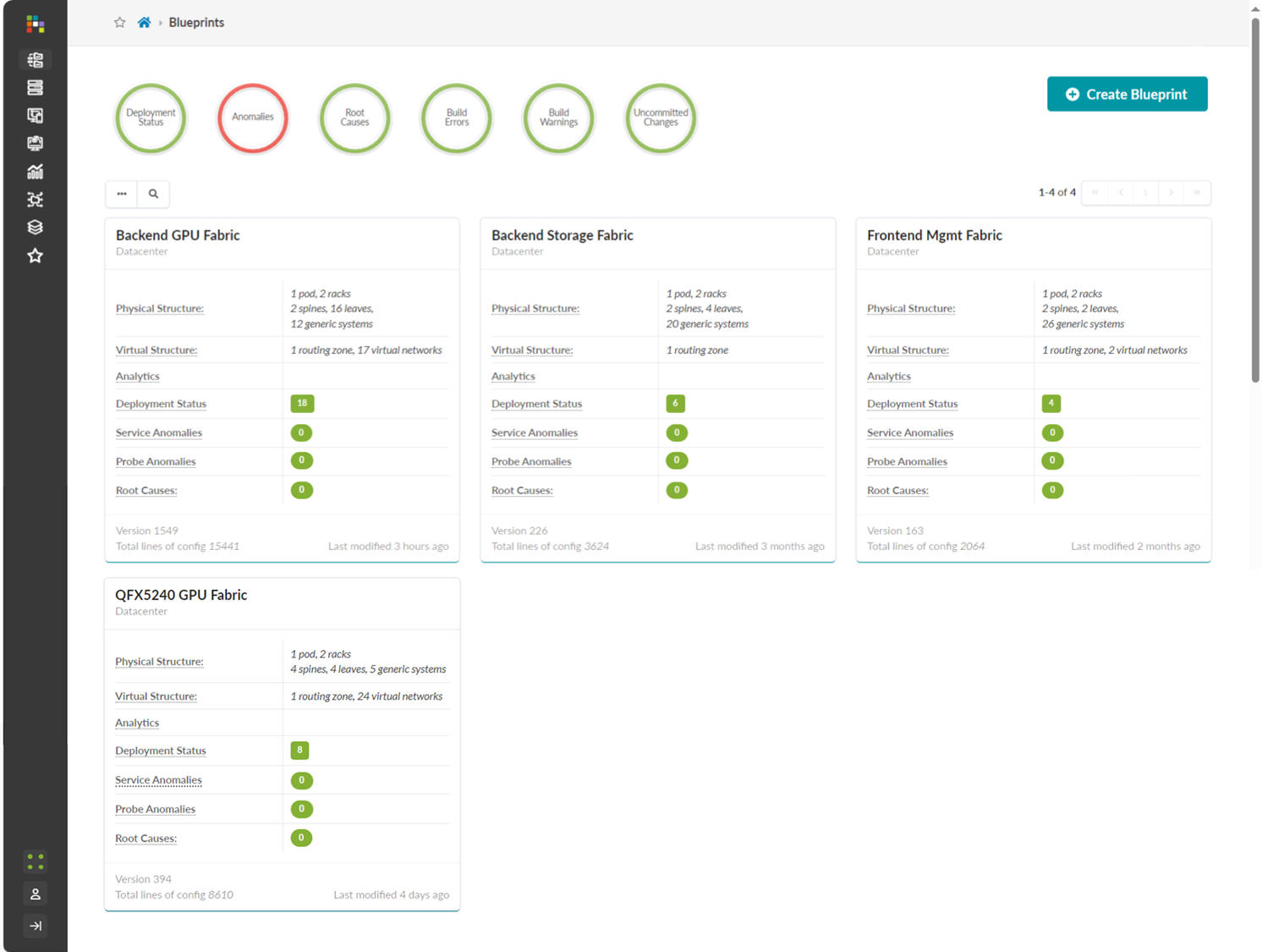
The Apstra Blueprints for all the fabrics have been created in the JVD AI lab, as shown in Figure 18.
Figure 18: AI Fabric Blueprints in Apstra
For more detailed information about installation and step-by-step configuration with Apstra, refer to the Juniper Apstra User Guide. Additional guidance in this walkthrough is provided in the form of notes.
Apstra: Configure Apstra Server and Apstra ZTP Server
A configuration wizard launches upon connecting to the Apstra server VM for the first time. At this point, passwords for the Apstra server, Apstra UI, and network configuration can be configured.
Apstra: Onboard the devices into Apstra
There are two methods for adding Juniper devices into Apstra for management: manually or in bulk using ZTP.
To add devices manually (recommended):
- In the Apstra UI navigate to Devices >> Agents >> Create Offbox Agents:
- This requires that the devices are preconfigured with a root password, a management IP and proper static routing if needed, as well as ssh Netconf, so that they can be accessed and configured by Apstra.
To add devices via ZTP:
- From the Apstra ZTP server, follow the ZTP steps described in the Juniper Apstra User Guide.
To add the QFX switches into Apstra, first log into the Apstra Web UI, choose the manual method of device addition as per above, and provide the appropriate username and password matching those preconfigured on the devices. Make sure the routers are configured accordingly.
It is best practice to avoid setting loopbacks, interfaces (except management interface), routing-instances (except management-instance) or any other settings as part of this baseline configuration.
Apstra sets the protocols LLDP and RSTP when the device is successfully Acknowledged.
Onboarding Devices
1) Apstra Web UI: Create Agent Profile
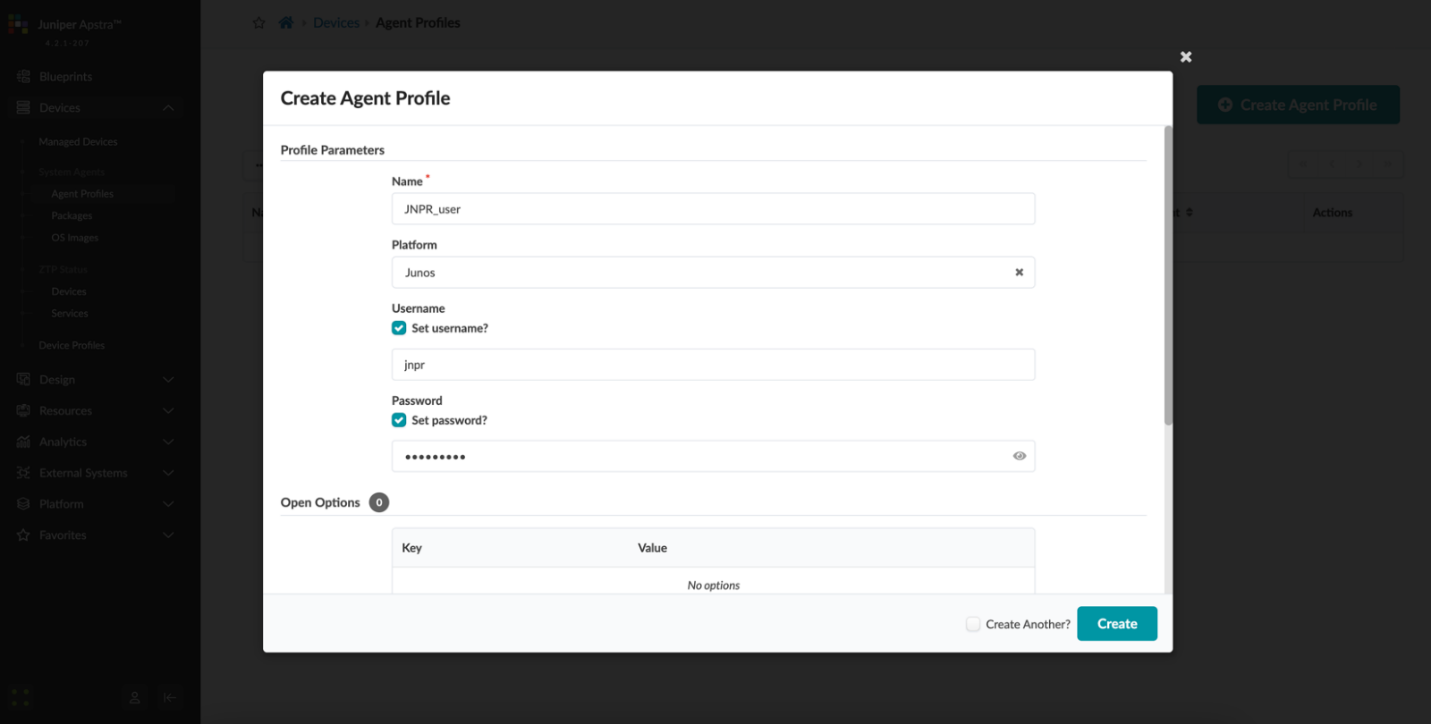
For the purposes of this JVD, the same username and password are used across all devices. Thus, only one Apstra Agent Profile is needed to onboard all the devices, making the process more efficient.
To create an Agent Profile, navigate to Devices >> Agent Profiles and then click on Create Agent Profile.
Figure 19: Creating an Agent Profile in Apstra
2) Apstra Web UI: Add Range of IP Addresses for Onboarding Devices
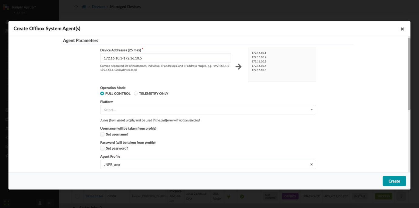
An IP address range can be provided to bulk onboard devices in Apstra. The ranges shown in the example below are shown for demonstration purposes only.
To onboard devices, navigate to Devices >> Agents and then click on Create Offbox Agents.
Figure 20: Adding a Range of IP Addresses in Apstra
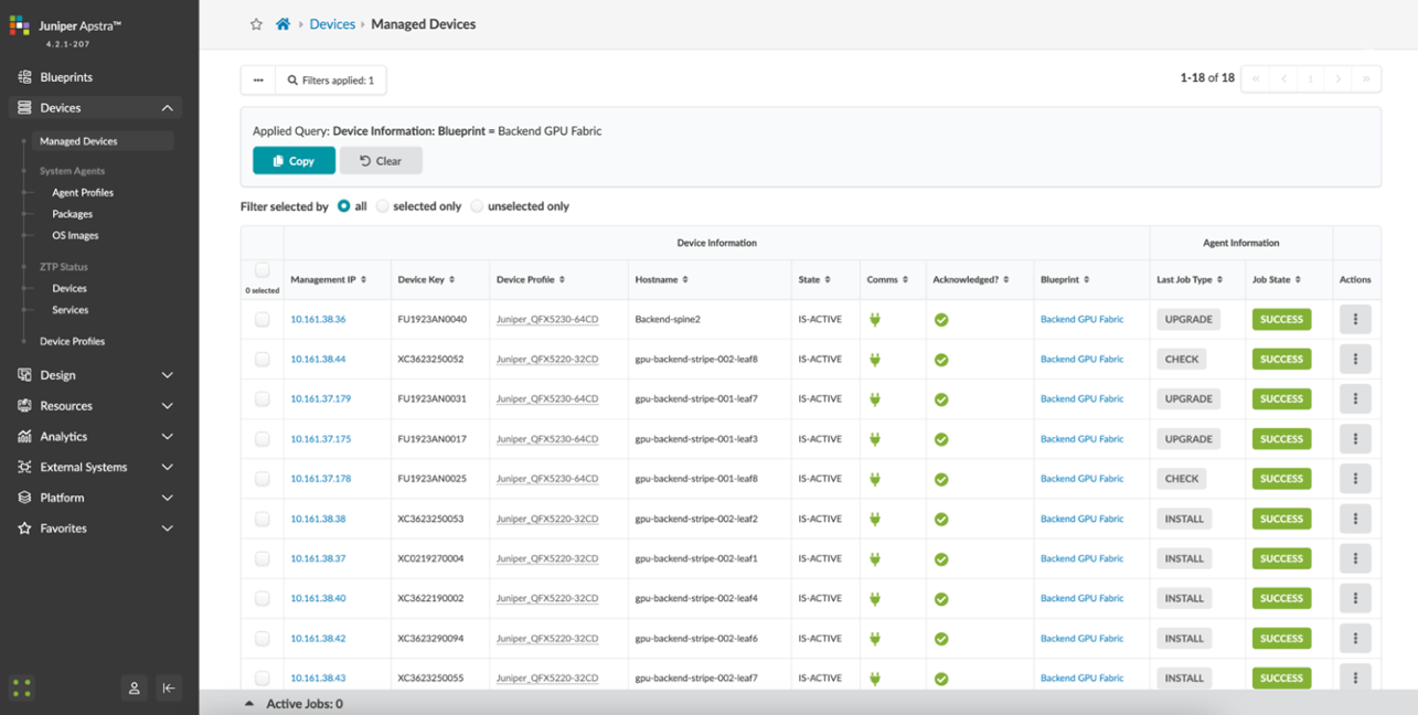
3) Apstra Web UI: Acknowledge Managed Devices for Use in Apstra Blueprints
Once the offbox agent creation has been successfully executed for each device, the devices must be acknowledged by the user to complete the onboarding and make them part of the Apstra Blueprints. This moves the device state from OOS-QUARANTINE to OOS-READY.
Figure 21: Acknowledging Managed Devices in Apstra Blueprints
Apstra: Fabric Provisioning
The following steps outline the provisioning of the GPU Backend Fabric with Apstra.
1) Apstra Web UI: Create Logical Devices and Interface Maps with Device Profiles
The GPU Backend fabric in Apstra uses a combination of QFX5230-64CD’s (stripe-1) and QFX5220-32CD’s (stripe-2) for the leaf nodes and QFX5230-64CD’s for the spines. Logical Devices and Interface Maps must be created for the two types of switches.
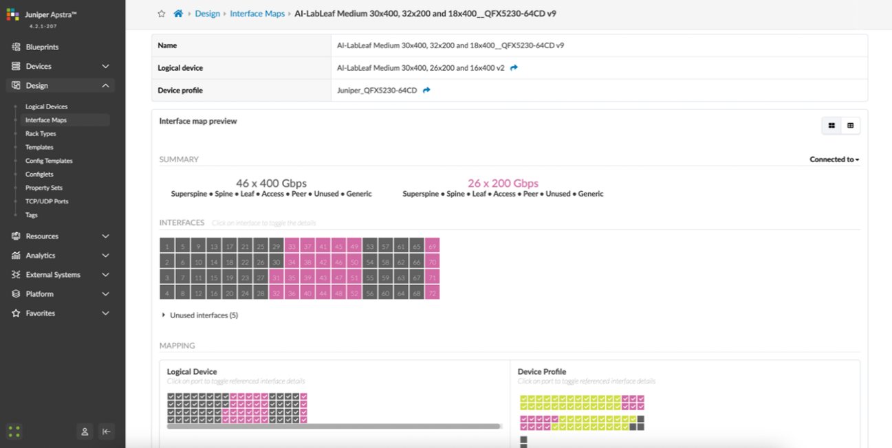
For the QFX5230-64CD leaf nodes, the Logical Device and Interface Map are shown in Figures 22 and 23:
Figure 22: Apstra Logical Device for the QFX5230 Leaf Nodes
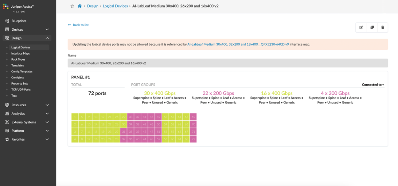
Figure 23: Apstra Interface Map for the QFX5230 Leaf Nodes
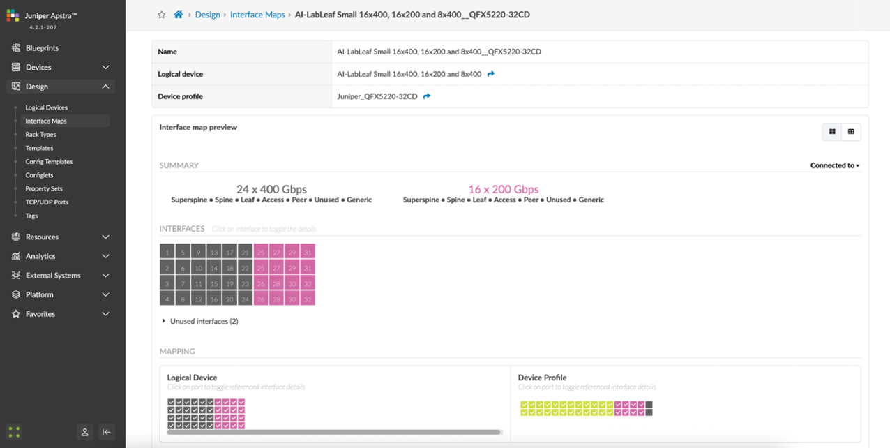
For the QFX5220 leaf nodes, the Logical Device and Interface Map are shown in Figures 24 and 25:
Figure 24: Apstra Logical Device for the QFX5220 Leaf Nodes
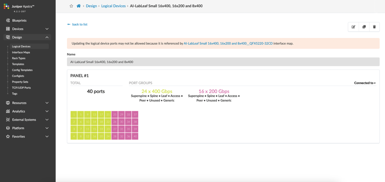
Figure 25: Apstra Interface Map for the QFX5220 Leaf Nodes
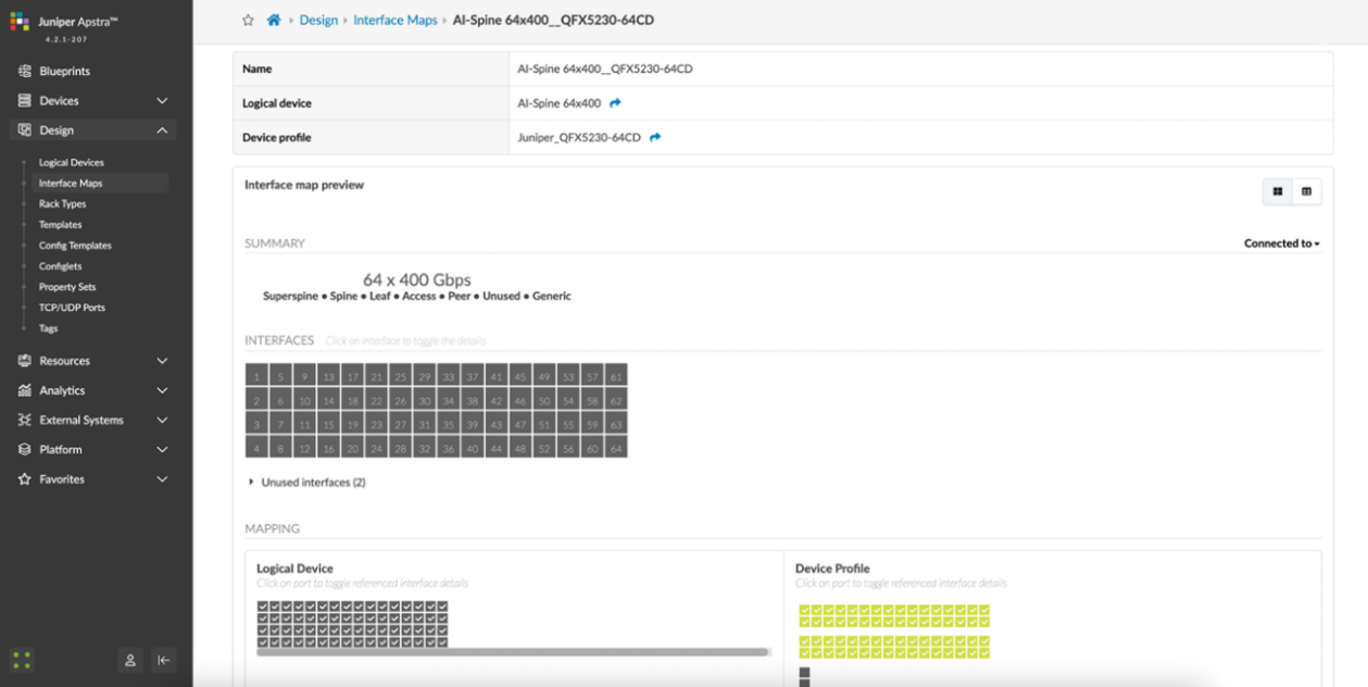
For the QFX5230 leaf nodes, the Logical Device and Interface Map are shown in Figures 26 and 27:
Figure 26: Apstra Logical Device for the QFX5230 Spine Nodes
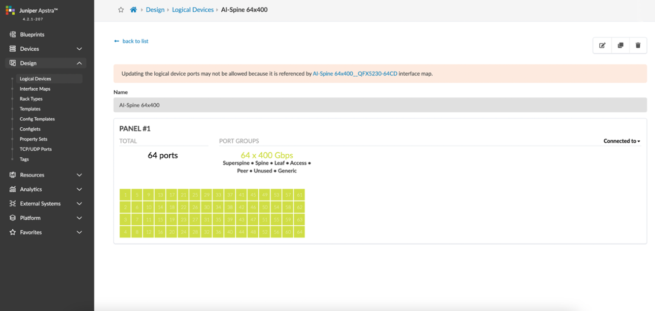
Figure 27: Apstra Interface Map for the QFX5230 Spine Nodes
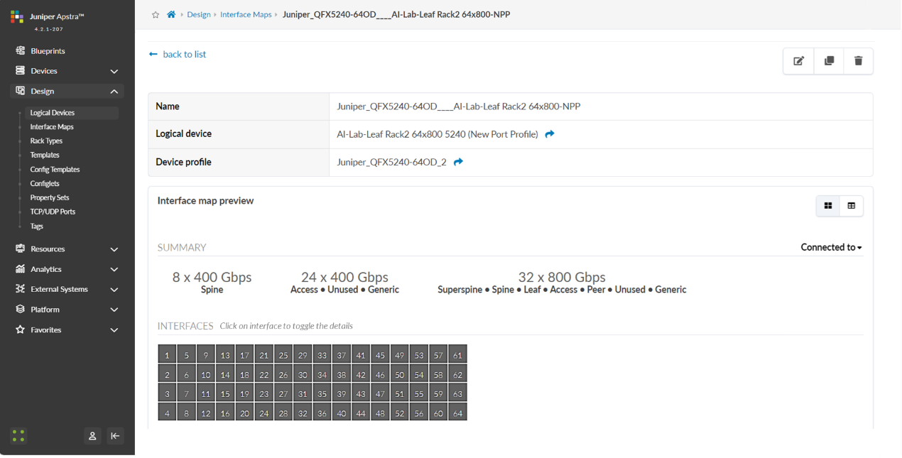
For the QFX5240 spine and leaf nodes, the Logical Device and Interface Map are shown in Figures 28-29 and 30-31 respectively.
The following table shows the differences between the old and the new port mappings.
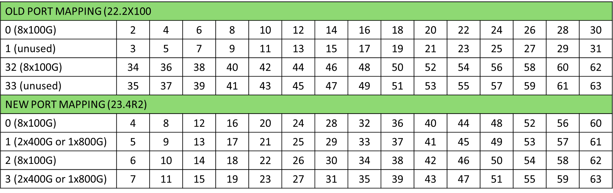
The Logical Device and Interface Map included below were created following the new port mapping.
Figure 28: Apstra Logical Device for the QFX5240 Spine Nodes
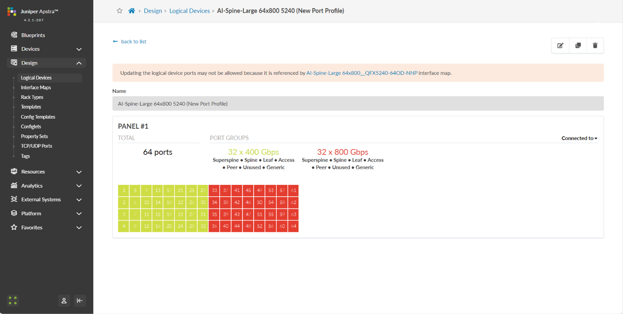
Figure 29: Apstra Interface Map for the QFX5240 Spine Nodes
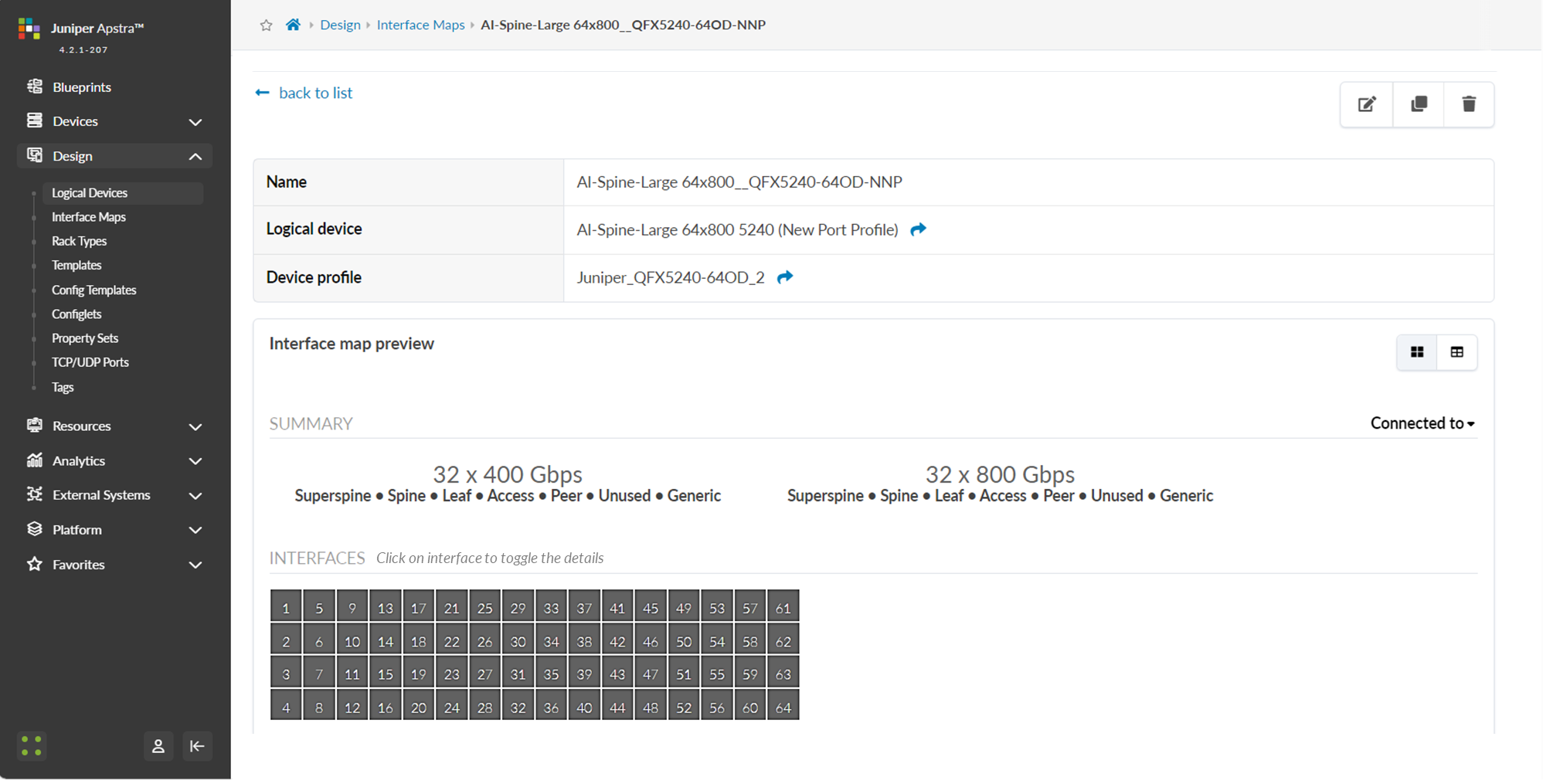
Figure 30: Apstra Interface Map for the QFX5240 Leaf Nodes
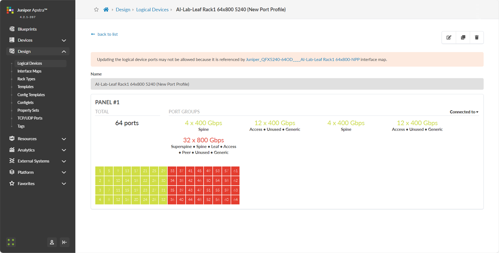
Figure 31: Apstra Logical Device for the QFX5240 Leaf Nodes
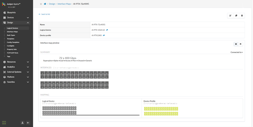
For the PTX10008 spine nodes also tested in cluster 1, the Logical Device and Interface Map are shown in Figures 32-33.
Figure 32: Apstra Interface Map for the PTX Spine Nodes
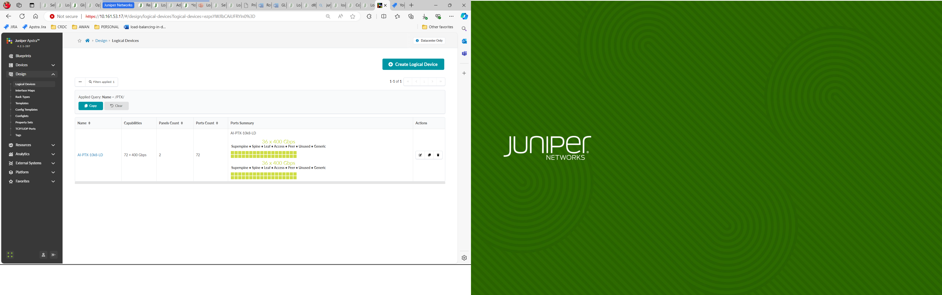
Figure 33: Apstra Logical Device for the PTX Spine Nodes
2) Apstra Web UI: Create Rack types and Template in Apstra for the GPU Backend Fabric
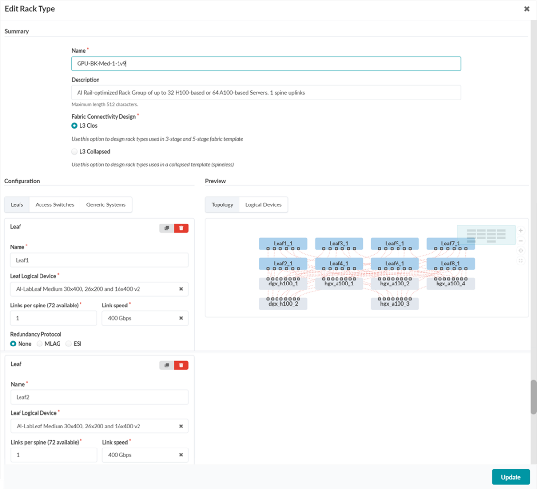
Once the Logical Devices and Interface Maps are created, create the necessary rack types for the GPU Backend fabric.
The design requires two rack types: one with the QFX5230 leaf nodes (stripe 1) and another with the QFX5220 leaf nodes (stripe 2).
For the sake of brevity, only the snippet of the QFX5230 rack type is shown in Figure 34.
Figure 34: Creating a Rack in Apstra
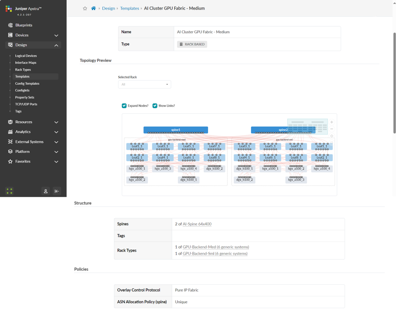
Once both the racks are ready, a Template is created in Apstra by navigating to Design -> Templates -> Create Template.
The new Template references the QFX5230 and QFX5220 rack types created in the previous step, and is deployed as a pure IP fabric, as shown in Figure 35.
Figure 35: Creating a Template in Apstra
3) Apstra Web UI: Create a Blueprint for GPU Backend Fabric
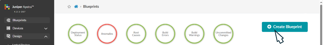
Once the Apstra Template is ready, create a Blueprint for the GPU Backend fabric by navigating to the Blueprints and clicking on Create Blueprint as shown in Figure 36.
Figure 36: Creating a Blueprint in Apstra
Provide a name for the new blueprint, select data center as the reference design, and select Rack-based. Then select the template that was created in the previous step which will include the two rack types that were created for the QFX5230 leaf nodes and the QFX5220 leaf nodes.
Figure 37: New Blueprint Attributes in Apstra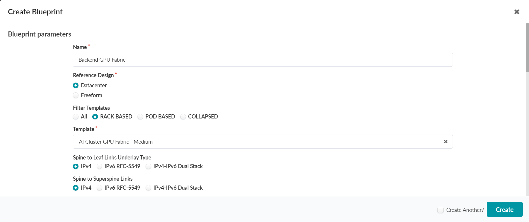
Once the blueprint is successfully initiated by Apstra, it will be included in the Blueprint dashboard as shown below.
Figure 38: New Blueprint Added to Blueprint Dashboard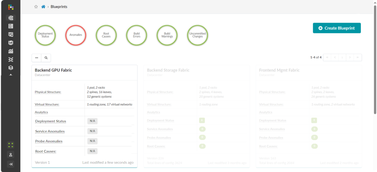
Notice that the Deployment Status, Service Anomalies, Probe Anomalies and Root Causes all shown as N/A. This is because you will need to complete additional steps that inlcudes mapping the different roles in the blueprint to the physical devices, defining which interfaces will be used, etc.
When you click on the blueprint name and enter the blueprint dashboard it will indicate that the blueprint has not been deployed yet.
Figure 39: New Blueprint’s dashboard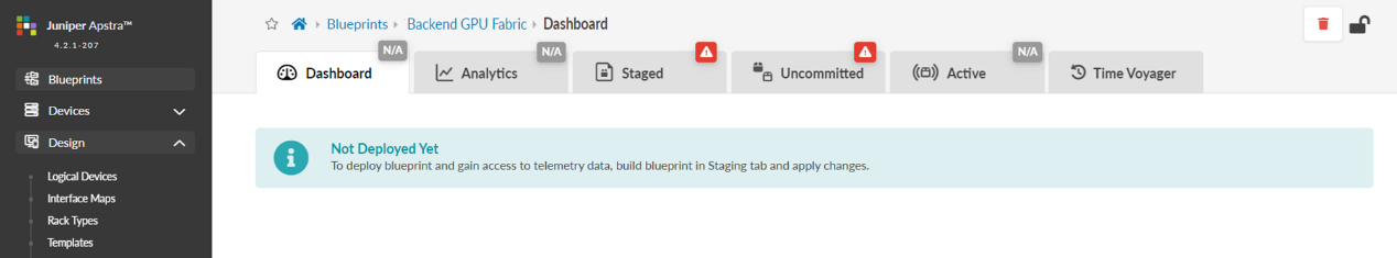
The Staged view as depicted in Figure 40 shows that the topology is correct, but attributes such as mandatory ASNs and loopback addressing for the spines and the leaf nodes, and the spine to leaf links addressing must be provided by the user.
Figure 40: Undeployed Blueprint Dashboard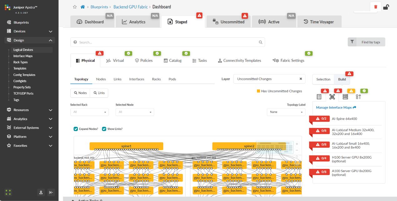
You will need to edit each one of these attributes and select from predefined pools of addresses and ASNs, as shown in the example on Figure 41, to fix this issue.
Figure 41: Selecting ASN Pool for Spine Nodes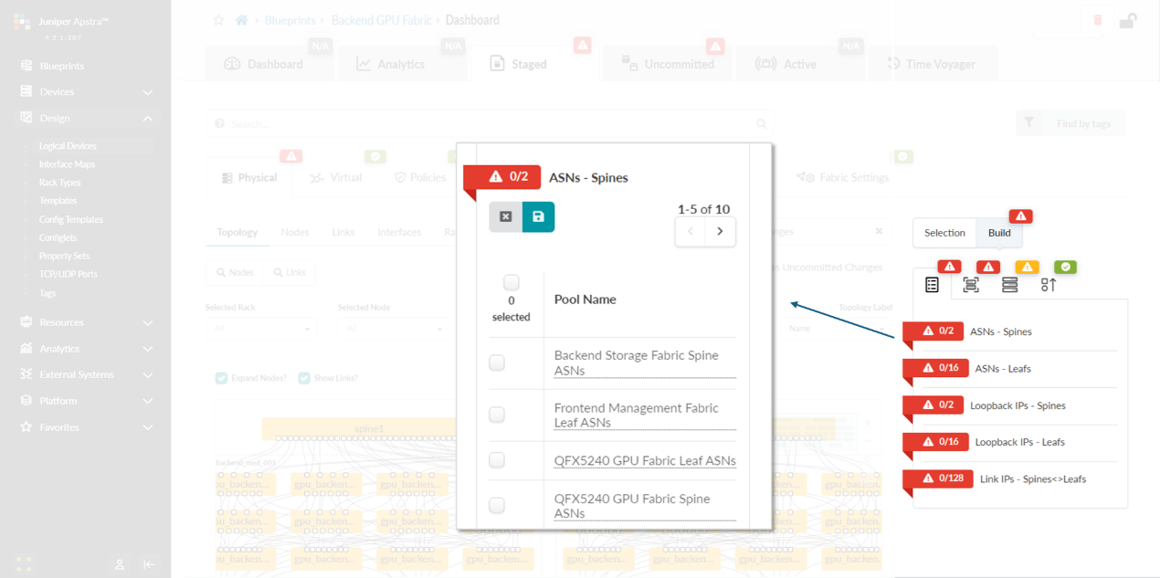
You will also need to select Interface Maps for each devices’ role and along with assignment of system IDs as shown in Figures 42-43.
Figure 42: Mapping Interface Maps to Spine Nodes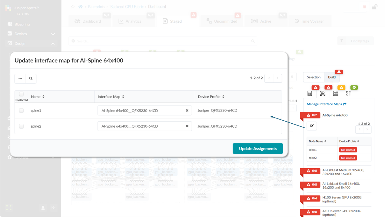
Figure 43: Mapping Spine Nodes to Physical Devices (System
IDs)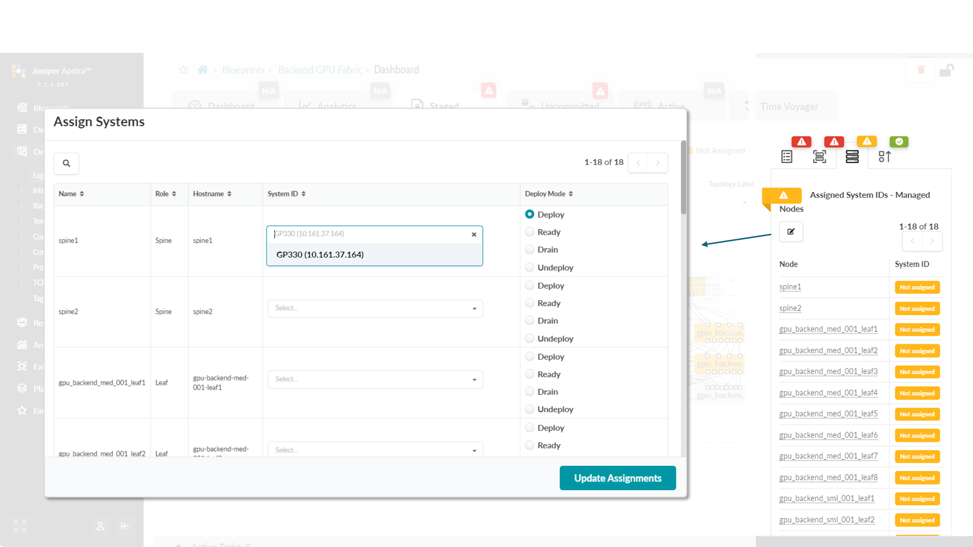
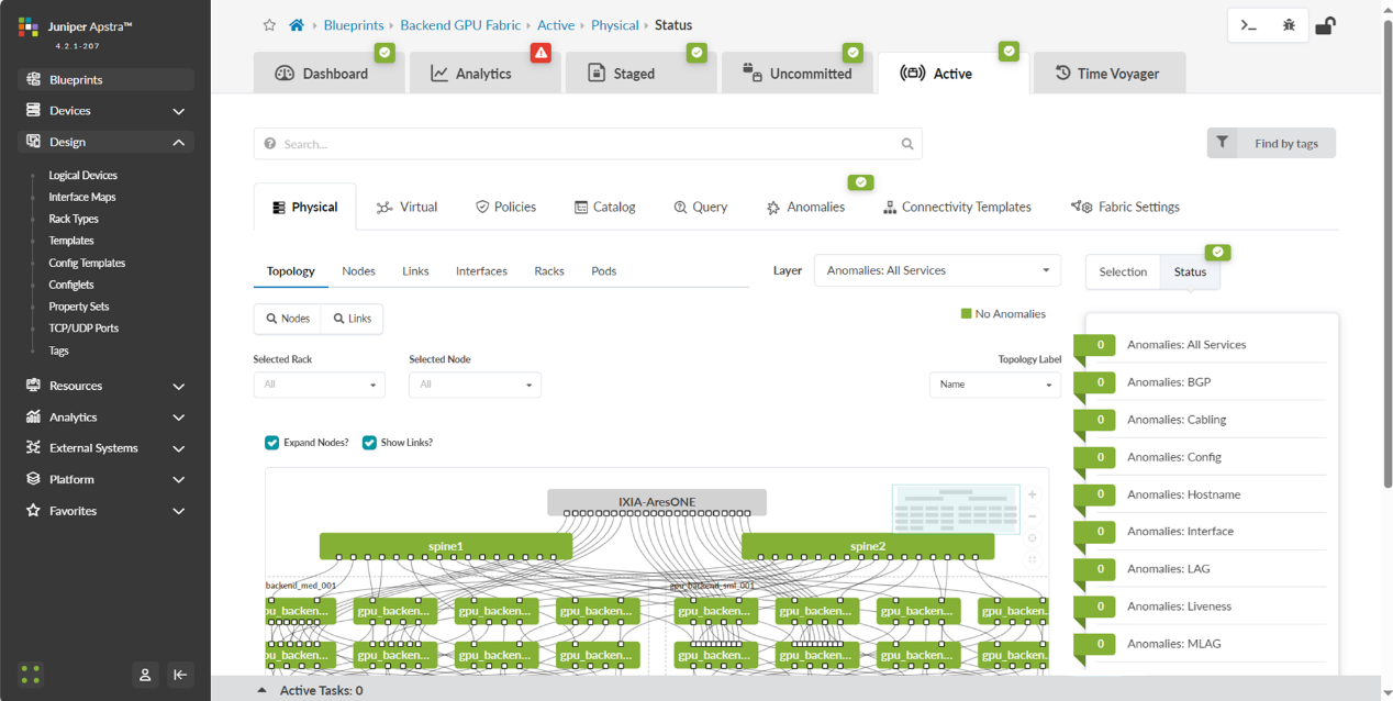
Once all these steps are completed, you can commit all the changes and Apstra will generate and push all the necessary vendor-specific configuration to the nodes. Once this has been completed you should be able to view an active blueprint that represents the successfully deployed fabric as shown in Figure 44.
Figure 44: Mapping Spine Nodes to Physical Devices 2 (System IDs)
Apstra Web UI: Creating Configlets in Apstra for DCQCN and DLB
As of Apstra 4.2.1, features such as ECN and PFC (DCQCN), and DLB are not natively available. Thus, to deploy the necessary configuration to enable these features on the fabric devices, Apstra Configlets are used.
The configlet used for the DCQCN and DLB features on the QFX leaf nodes is as follows:
-
/* DLB configuration */

hash-key {

    family inet {

        layer-3;

        layer-4;

    }

}

enhanced-hash-key {

    ecmp-dlb {

        flowlet {

            inactivity-interval 128;

            flowset-table-size 2048;

        }

        ether-type {

            ipv4;

            ipv6;

        }

        sampling-rate 1000000;

    }

}

protocols {

    bgp {

        global-load-balancing {

            load-balancer-only;

        }

    }

}

/* DCQCN configuration */

class-of-service {

    classifiers {

        dscp mydscp {

            forwarding-class CNP {

                loss-priority low code-points 110000;

            }

            forwarding-class NO-LOSS {

                loss-priority low code-points 011010;

            }

        }

    }

    drop-profiles {

        dp1 {

            interpolate {

                fill-level [ 55 90 ];

                drop-probability [ 0 100 ];

            }

        }

    }

    shared-buffer {

        ingress {

       buffer-partition lossless {

          percent 66;

          dynamic-threshold 10;

       }

       buffer-partition lossless-headroom {

          percent 24;

       }

       buffer-partition lossy {

          percent 10;

       }

      }

      egress {

        buffer-partition lossless {

           percent 66;

        }

        buffer-partition lossy {

           percent 10;

        }

      }

    }

    forwarding-classes {

        class CNP queue-num 3;

        class NO-LOSS queue-num 4 no-loss pfc-priority 3;

    }

    congestion-notification-profile {

        cnp {

            input {

                dscp {

                    code-point 011010 {

                        pfc;

                    }

                }

            }

            output {

                ieee-802.1 {

                    code-point 011 {

                        flow-control-queue 4;

                    }

                }

            }

        }

    }

    interfaces {

        et-* {

            congestion-notification-profile cnp;

            scheduler-map sm1;

            unit * {

                classifiers {

                    dscp mydscp;

                }

            }

        }

    }

    scheduler-maps {

        sm1 {

            forwarding-class CNP scheduler s2-cnp;

            forwarding-class NO-LOSS scheduler s1;

        }

    }

    schedulers {

        s1 {

            drop-profile-map loss-priority any protocol any drop-profile dp1;

            explicit-congestion-notification;

        }

        s2-cnp {

            transmit-rate percent 5;

            priority strict-high;

        }

    }

}
The configlet used for the DCQCN and DLB features on the QFX spine nodes is as follows:
-
/* DLB configuration */

hash-key {

    family inet {

        layer-3;

        layer-4;

    }

}

enhanced-hash-key {

    ecmp-dlb {

        flowlet {

            inactivity-interval 128;

            flowset-table-size 2048;

        }

        ether-type {

            ipv4;

            ipv6;

        }

        sampling-rate 1000000;

    }

}

protocols {

    bgp {

        global-load-balancing {

            helper-only;

        }

    }

}

/* DCQCN configuration */

class-of-service {

    classifiers {

        dscp mydscp {

            forwarding-class CNP {

                loss-priority low code-points 110000;

            }

            forwarding-class NO-LOSS {

                loss-priority low code-points 011010;

            }

        }

    }

    drop-profiles {

        dp1 {

            interpolate {

                fill-level [ 55 90 ];

                drop-probability [ 0 100 ];

            }

        }

    }

    shared-buffer {

        ingress {

       buffer-partition lossless {

          percent 66;

          dynamic-threshold 10;

       }

       buffer-partition lossless-headroom {

          percent 24;

       }

       buffer-partition lossy {

          percent 10;

       }

      }

      egress {

        buffer-partition lossless {

           percent 66;

        }

        buffer-partition lossy {

           percent 10;

        }

      }

    }

    forwarding-classes {

        class CNP queue-num 3;

        class NO-LOSS queue-num 4 no-loss pfc-priority 3;

    }

    congestion-notification-profile {

        cnp {

            input {

                dscp {

                    code-point 011010 {

                        pfc;

                    }

                }

            }

            output {

                ieee-802.1 {

                    code-point 011 {

                        flow-control-queue 4;

                    }

                }

            }

        }

    }

    interfaces {

        et-* {

            congestion-notification-profile cnp;

            scheduler-map sm1;

            unit * {

                classifiers {

                    dscp mydscp;

                }

            }

        }

    }

    scheduler-maps {

        sm1 {

            forwarding-class CNP scheduler s2-cnp;

            forwarding-class NO-LOSS scheduler s1;

        }

    }

    schedulers {

        s1 {

            drop-profile-map loss-priority any protocol any drop-profile dp1;

            explicit-congestion-notification;

        }

        s2-cnp {

            transmit-rate percent 5;

            priority strict-high;

        }

    }

}
The configuration used for the DCQCN features on the PTX10008 as spine devices is as follows:
NOTE: when using PTX10008 as a spine node, GLB is not an option.
-
/* DCQCN configuration */

class-of-service {

        classifiers {

                dscp mydscp {

                        forwarding-class rdma-cnp {

                                loss-priority low code-points 110000;

                        }

                        forwarding-class rdma-ecn {

                                loss-priority low code-points 011010;

                        }

                }

        }

        drop-profiles {

        dp-ecn {

                fill-level 1 drop-probability 0;

                fill-level 3 drop-probability 100;

                }

        }

        forwarding-classes {

        class network-control queue-num 3;

        class other queue-num 2;

        class rdma-cnp queue-num 0;

        class rdma-ecn queue-num 1 no-loss;

        }

        monitoring-profile {

        mp1 {

                        export-filters filt1 {

                                peak-queue-length {

                                percent 0;

                        }

                        queue [ 0 1 ];

                }

        }

}

interfaces {

    et-* {

        scheduler-map sched-map-aiml;

        monitoring-profile mp1;

        unit * {

            classifiers {

                dscp mydscp;

            }

        }

    }

}

scheduler-maps {

    sched-map-aiml {

        forwarding-class network-control scheduler sched-nc;

        forwarding-class other scheduler sched-other;

        forwarding-class rdma-cnp scheduler sched-cnp;

        forwarding-class rdma-ecn scheduler sched-ecn;

    }

}

schedulers {

    sched-cnp {

        transmit-rate percent 1;

        priority high;

    }

    sched-ecn {

        transmit-rate percent 97;

        buffer-size temporal 4063;

        priority medium-high;

        drop-profile-map loss-priority any protocol any drop-profile dp-ecn;

        explicit-congestion-notification;

    }

    sched-nc {

        transmit-rate percent 1;

        priority medium-high;

    }

    sched-other {

        priority low;

    }

}
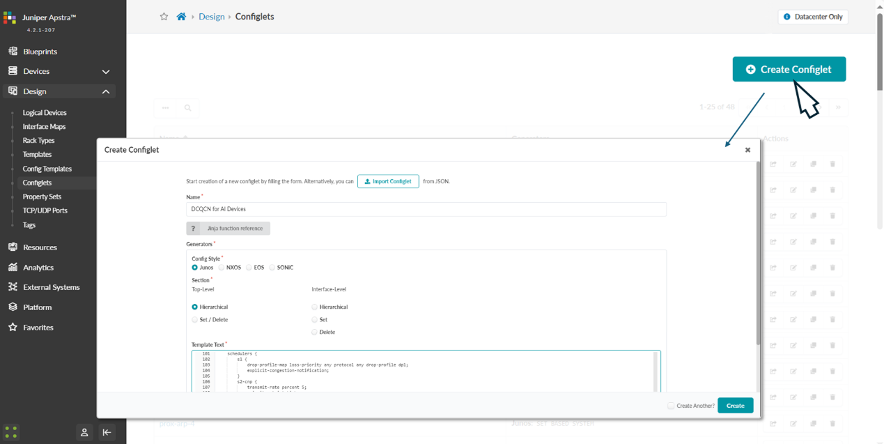
To create the DCQCN configlets navigate to Design -> Configlets -> Create Configlet, and click on Create configlet.
Provide a name for the config, select the operating system, vendor and configuration mode and paste the above configuration snippet on the template text box as shown below:
Figure 45: DCQCN Configlet Creation in Apstra
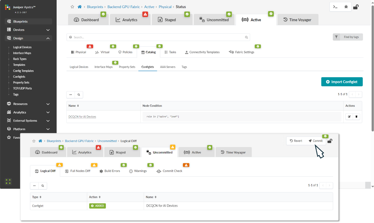
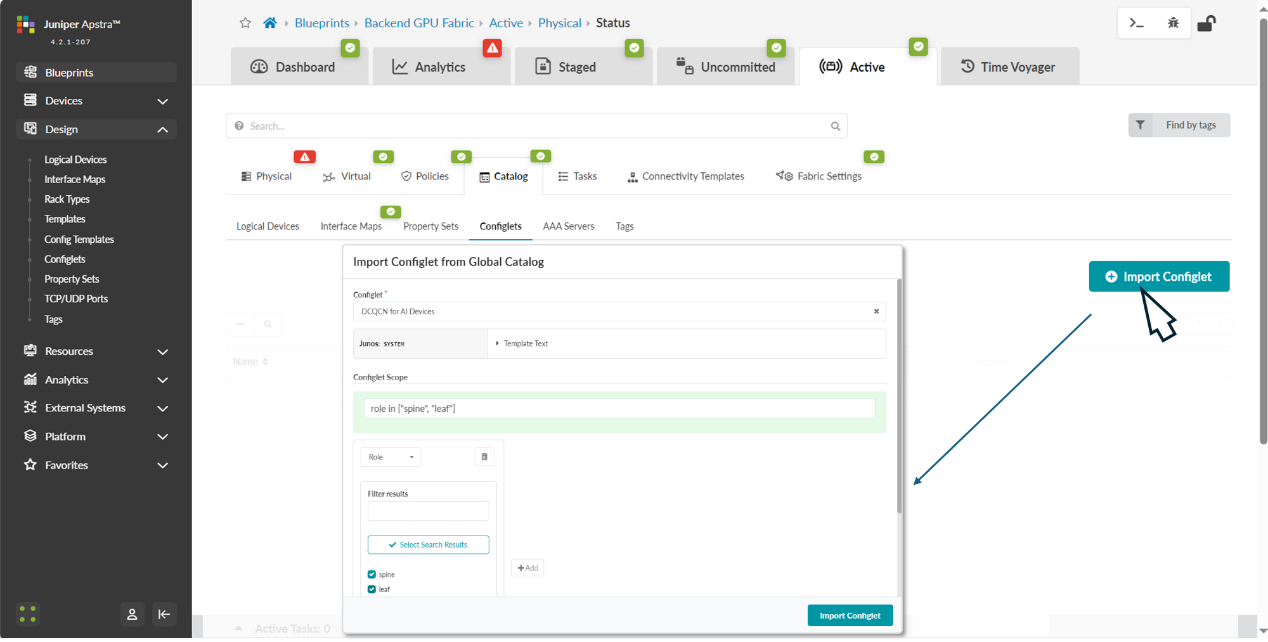
The configlet should be applied to the devices, both leaf and spine roles within the blueprint. Navigate back to the blueprint dashboard and the move to Staged -> Catalog -> Import. Select the configlet you want to apply, and the device role where you want to apply it.
Figure 46: Applying DCQCN Configlets to Devices in Apstra
After successfully importing the configlet into the blueprint it should be listed in the catalog. You need to commit the changes for the configuration to be deployed to the devices.
Figure 47: Applying DCQCN Configlets to Devices in Apstra