ON THIS PAGE
Identifying NICs and GPUs Mappings and Assigning the Appropriate Interface Name
How to Change a NIC’s Interface Name, and Assign IP Addresses and Routes
To Map an Interface Name to a Specific NIC (Physical Interface)
To Change the Current IP Address or Assign an IP Address to the NIC
NVIDIA TOS/DSCP Configuration for RDMA-CM QPS (RDMA Traffic)
Configuring NVIDIA to Use the Management Interface for NCCL Control Traffic
NVIDIA Configuration
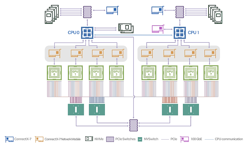
NVIDIA® ConnectX® family of network interface cards (NICs) offer advanced hardware offload and acceleration features, and speeds up to 400G, supporting both Ethernet and Infiniband protocols.
Always refer to the official manufacturer documentation when making changes. This section provides some guidelines based on the AI JVD lab testing.
Converting NVIDIA ConnectX NICs from Infiniband to Ethernet
By default, the NVIDIA ConnectX NICs are set to operate as Infiniband interfaces and must be converted to Ethernet using the mlxconfig tool.
1) Check the status of the ConnectX NICs using sudo mst status.
-
user@A100-01:/dev/mst$ sudo mst -h

Usage:

    /usr/bin/mst {start|stop|status|remote|server|restart|save|load|rm|add|help|version|gearbox|cable} Type "/usr/bin/mst help" for detailed help

user@A100-01:/dev/mst$ sudo mst status | egrep "module|load"

MST modules:

    MST PCI module loaded

    MST PCI configuration module loaded
Start the mst service or load the mst modules if necessary.
Example:
-
user@H100-01:~$ sudo mst start

Starting MST (Mellanox Software Tools) driver set

Loading MST PCI module - Success

[warn] mst_pciconf is already loaded, skipping

Create devices

Unloading MST PCI module (unused) - Success

user@A100-01:~/scripts$ sudo mst status

MST modules:

------------

    MST PCI module is not loaded

    MST PCI configuration module loaded
The example shows “MST PCI module is not loaded”. To load it, use the command modprobe mst_pci.
-
user@A100-01:/dev/mst$ sudo modprobe mst_pci

user@A100-01:/dev/mst$ sudo mst status

MST modules:

------------

    MST PCI module loaded

    MST PCI configuration module loaded
2) Identify the interface that you want to convert,
This sudo mst status -v command will provide a list of Mellanox devices (ConnectX-6 and ConnectX-7 NICs) detected on the system, along with their type, Mellanox device name, PCI addresses, RDMA interface name, NET interface name, and NUMA ID, as shown in the example below:
-
user@A100-01:/dev/mst$ sudo mst status -v


MST modules:

------------

    MST PCI module loaded

    MST PCI configuration module loaded


PCI devices:

------------


DEVICE_TYPE         MST                         PCI      RDMA     NET                NUMA

ConnectX7(rev:0)    /dev/mst/mt4129_pciconf7.1  cb:00.1  mlx5_13  net-eth13          1

ConnectX7(rev:0)    /dev/mst/mt4129_pciconf7    cb:00.0  mlx5_12  net-gpu6_eth       1

ConnectX7(rev:0)    /dev/mst/mt4129_pciconf6.1  c8:00.1  mlx5_11  net-enp200s0f1np1  1

ConnectX7(rev:0)    /dev/mst/mt4129_pciconf6    c8:00.0  mlx5_10  net-gpu7_eth       1

ConnectX7(rev:0)    /dev/mst/mt4129_pciconf5.1  8e:00.1  mlx5_19  net-eth19          1

ConnectX7(rev:0)    /dev/mst/mt4129_pciconf5    8e:00.0  mlx5_18  net-gpu5_eth       1

ConnectX7(rev:0)    /dev/mst/mt4129_pciconf4.1  8b:00.1  mlx5_17  net-enp139s0f1np1  1

ConnectX7(rev:0)    /dev/mst/mt4129_pciconf4    8b:00.0  mlx5_1   net-gpu4_eth       1

ConnectX7(rev:0)    /dev/mst/mt4129_pciconf3.1  52:00.1  mlx5_3   net-enp82s0f1np1   0

ConnectX7(rev:0)    /dev/mst/mt4129_pciconf3    52:00.0  mlx5_2   net-gpu3_eth       0

ConnectX7(rev:0)    /dev/mst/mt4129_pciconf2.1  51:00.1  mlx5_1   net-enp81s0f1np1   0

ConnectX7(rev:0)    /dev/mst/mt4129_pciconf2    51:00.0  mlx5_0   net-gpu2_eth       0

ConnectX7(rev:0)    /dev/mst/mt4129_pciconf1.1  11:00.1  mlx5_9   net-enp17s0f1np1   0

ConnectX7(rev:0)    /dev/mst/mt4129_pciconf1    11:00.0  mlx5_8   net-gpu1_eth       0

ConnectX7(rev:0)    /dev/mst/mt4129_pciconf0.1  0e:00.1  mlx5_7   net-enp14s0f1np1   0

ConnectX7(rev:0)    /dev/mst/mt4129_pciconf0    0e:00.0  mlx5_6   net-gpu0_eth       0

ConnectX6DX(rev:0)  /dev/mst/mt4125_pciconf0.1  2c:00.1  mlx5_5   net-enp44s0f1np1   0

ConnectX6DX(rev:0)  /dev/mst/mt4125_pciconf0    2c:00.0  mlx5_4   net-mgmt_eth       0

ConnectX6(rev:0)    /dev/mst/mt4123_pciconf0.1  a9:00.1  mlx5_15  net-eth15          1

ConnectX6(rev:0)    /dev/mst/mt4123_pciconf0    a9:00.0  mlx5_14  net-weka_eth       1


Cable devices:

---------------

mt4129_pciconf7_cable_0

mt4129_pciconf6_cable_0

mt4129_pciconf5_cable_0

mt4129_pciconf4_cable_0

mt4129_pciconf3_cable_0

mt4129_pciconf2_cable_0

mt4129_pciconf1_cable_0

mt4129_pciconf0_cable_0

mt4125_pciconf0_cable_0

mt4123_pciconf0_cable_0
For the first interface in the list, you can identify the following:
- Type = ConnectX7(rev:0)
- Mellanox device name = mt4129_pciconf7 (/dev/mst/mt4129_pciconf7)
- PCI addresses = cb:00.0
- RDMA interface name = mlx5_12
- NET interface name = net-gpu6_eth
-
NUMA = 1
Notice that for some of the interfaces the name follows the standard Linux interface naming scheme (e.g. net-enp14s0f1np1), while others do not (e.g. net-gpu0_eth). The interface names that do not follow the standard are user defined names for easy identification purposes. That means the default name was changed in the /etc/netplan/. We will show an example of how to do this later in this section.
3) Identify what mode a given interface is running using
mlxconfig -d <device> query
Example:
-
user@A100-01:~/scripts$ sudo mlxconfig -d /dev/mst/mt4129_pciconf7query | grep LINK_TYPE

        LINK_TYPE_P1     IB(1)

        LINK_TYPE_P2     IB(1)  <= indicates link is operating in Infiniband mode
Notice that you need to use the Mellanox device name, including the path (/dev/mst/mt4129_pciconf7).
Also, LINK_TYPE_P1 and LINK_TYPE_P2 refer to the two physical ports in a dual-port Mellanox adapter.
4) If an interface is operating in Infiniband mode, you can change the mode for ethernet mode using
mlxconfig -d <device> set [LINK_TYPE_P1=<link_type>] [LINK_TYPE_P2=<link_type>]
Example
-
user@A100-01:~/scripts$ sudo mlxconfig -d /dev/mst/mt4129_pciconf7 set LINK_TYPE_P1=2 LINK_TYPE_P2=2

Device #1:

----------

Device type:        ConnectX7

Name:               MCX755106AS-HEA_Ax

Description:        NVIDIA ConnectX-7 HHHL Adapter Card; 200GbE (default mode) / NDR200 IB; Dual-port QSFP112; PCIe 5.0 x16 with x16 PCIe extension option; Crypto Disabled; Secure Boot Enabled

Device:             /dev/mst/mt4129_pciconf7

Configurations:                                          Next Boot       New

        LINK_TYPE_P1                                ETH(2)               ETH(2)

        LINK_TYPE_P2                                ETH(2)               ETH(2)

 Apply new Configuration? (y/n) [n] : y

Applying... Done!

-I- Please reboot machine to load new configurations.

user@A100-01:~/scripts$ sudo mlxconfig -d /dev/mst/mt4129_pciconf7query | grep LINK_TYPE

        LINK_TYPE_P1     ETH(2)

        LINK_TYPE_P2     ETH(2)   <= indicates link is operating in Ethernet mode
Again, notice that you need to use the Mellanox device name, including the path (/dev/mst/mt4129_pciconf7).
To check the status of the interface you can use the mlxlink:
-
user@A100-01:/dev/mst$ sudo mlxlink -d /dev/mst/mt4129_pciconf4

Operational Info

----------------

State                              : Active

Physical state                     : LinkUp

Speed                              : 200G

Width                              : 4x

FEC                                : Standard_RS-FEC - (544,514)

Loopback Mode                      : No Loopback

Auto Negotiation                   : ON

Supported Info

--------------

Enabled Link Speed (Ext.)          : 0x00003ff2 (200G_2X,200G_4X,100G_1X,100G_2X,100G_4X,50G_1X,50G_2X,40G,25G,10G,1G)

Supported Cable Speed (Ext.)       : 0x000017f2 (200G_4X,100G_2X,100G_4X,50G_1X,50G_2X,40G,25G,10G,1G)

Troubleshooting Info

--------------------

Status Opcode                      : 0

Group Opcode                       : N/A

Recommendation                     : No issue was observed

Tool Information

----------------

Firmware Version                   : 28.39.2048

amBER Version                      : 2.22

MFT Version                        : mft 4.26.0-93
For more details you can refer to:
HowTo Find Mellanox Adapter Type and Firmware/Driver version (Linux) (nvidia.com)
Firmware Support and Downloads - Identifying Adapter Cards (nvidia.com)
Identifying NICs and GPUs Mappings and Assigning the Appropriate Interface Name
NICs can be used by any GPU at any time; it is not hard coded that a given GPU can only communicate with the outside world using a specific NIC card. However, there are preferred communication paths between GPUs and NICs, which in some cases could be seen as a 1:1 correspondence between them. This will be shown in the steps below.
NCCL (NVIDIA Collective Communications Library) will choose the path that has the best connection from a given GPU to one of the NICs.
To identify the paths selected by NCCL and what the best path between a GPU and a NIC is, follow these steps:
Use the nvidia-smi topo -m command, which displays topological information about the system, to identify the connection type between GPUs and NICs:
EXAMPLES:
- DGX H100:
Figure 48. Nvidia H100 System Management Interface (SMI) system
topology information 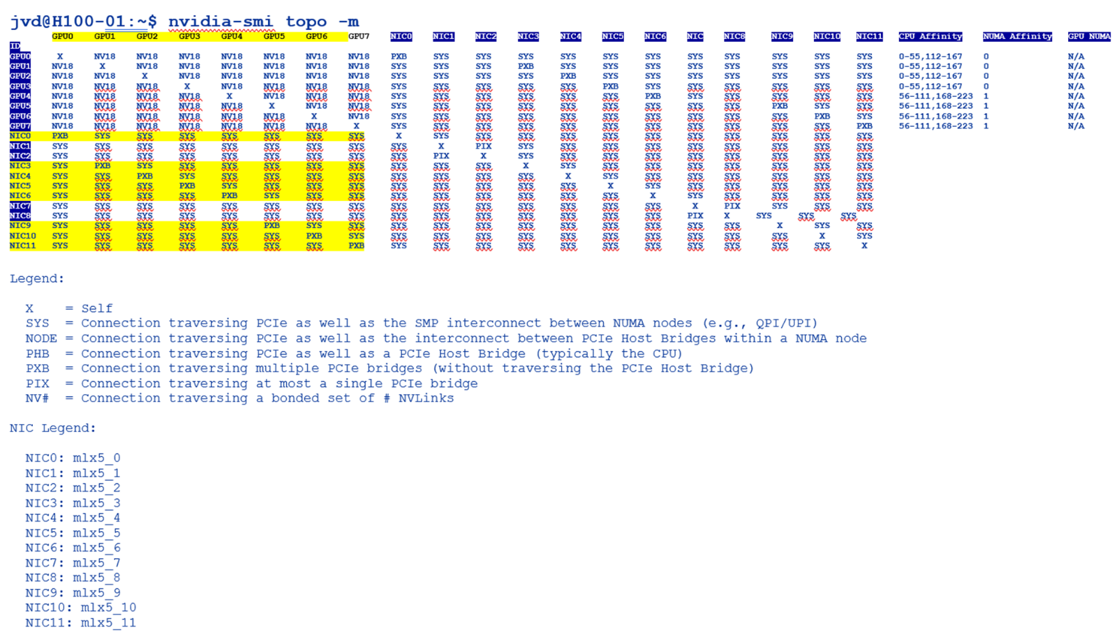
System Management Interface SMI | NVIDIA Developer
Based on our research:
Table 21: Performance per connection type
| Connection Type | Description | Performance |
| PIX | PCIe on the same switch | Good |
| PXB | PCIe through multiple switches, but not host bridge | Good |
| PHB | PCIe switch and across a host bridge on the same NUMA - uses CPU | OK |
| NODE | PCIe switch and across multiple host bridge on the same NUMA | Bad |
| SYS | PCIe switch and across QPI/UPI bus between NUMA nodes - uses CPU | Very Bad |
| NV# | NVLink | Very Good |
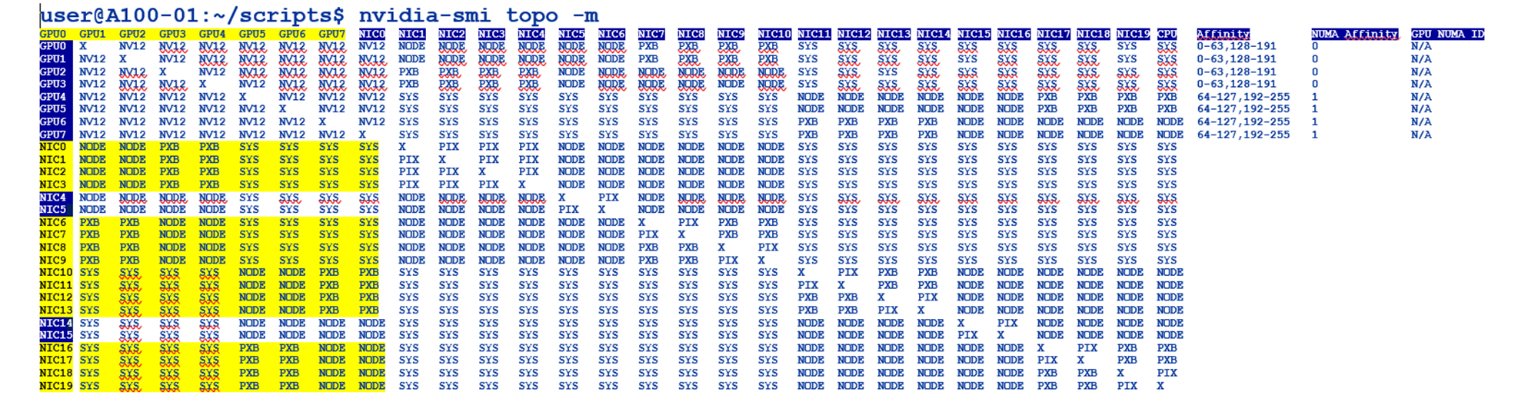
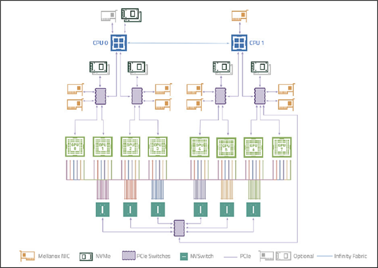
- HGX A100:
Figure 49.Nvidia A100 System Management Interface (SMI) system topology information
Identify PBX Connections
If you focus on the highlighted sections of the nvidia-smi output, you can see that for each GPU there is one or more NIC connection(s) of type PXB. This is the preferred “direct” path from each GPU to a given NIC. That means, when the GPU needs to communicate to a remote device, it will use one of these specific NICs, as the first option.
- DGX H100:
Figure 50. Nvidia H100 System Management Interface (SMI) system
topology PBX connections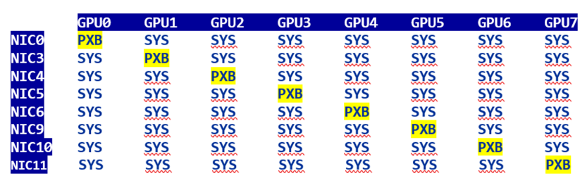
- HGX A100:
Figure 51. Nvidia A100 System Management Interface (SMI) system
topology PBX connections 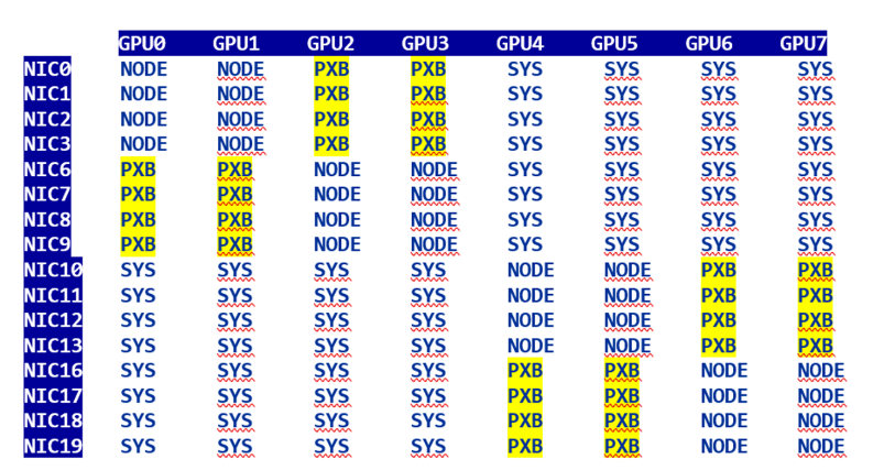
You can also find these mappings in Nvidia’s A100 or H100 user guides.
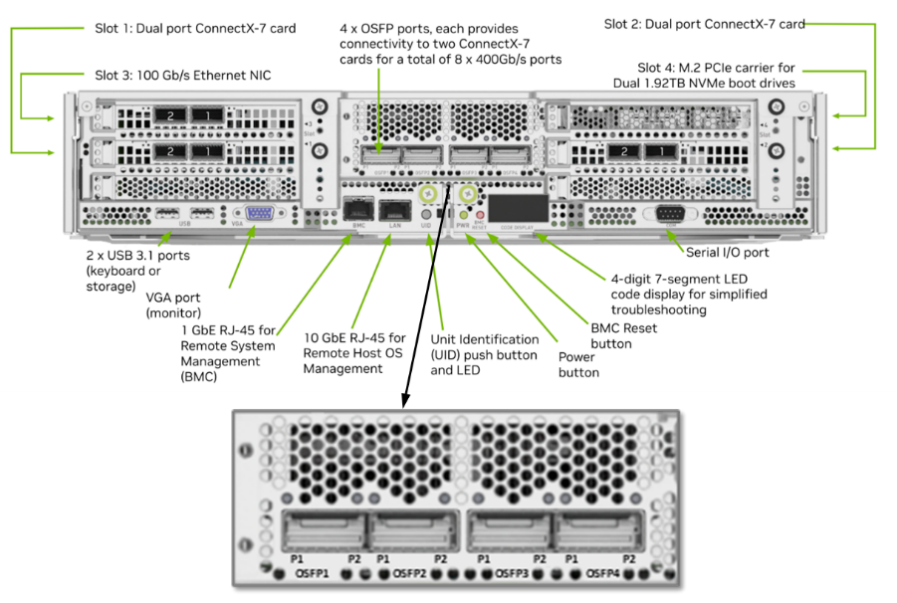
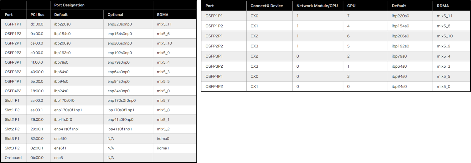
For example, on an DGX H100/H200 System the port mappings according to the NVIDIA's DGX H100/H200 System User Guide table 5 and table 6 is as follows:
Table 22: GPU to NIC Mappings
| Port | ConnectX | GPU | Default | RDMA | NIC |
| OSFP4P2 | CX1 | 0 | ibp24s0 | mlx5_0 | NIC0 |
| OSFP3P2 | CX3 | 1 | ibp64s0 | mlx5_3 | NIC3 |
| OSFP3P1 | CX2 | 2 | ibp79s0 | mlx5_4 | NIC4 |
| OSFP4P1 | CX0 | 3 | ibp94s0 | mlx5_5 | NIC5 |
| OSFP1P2 | CX1 | 4 | ibp154s0 | mlx5_6 | NIC6 |
| OSFP2P2 | CX3 | 5 | ibp192s0 | mlx5_9 | NIC9 |
| OSFP2P1 | CX2 | 6 | ibp206s0 | mlx5_10 | NIC10 |
| OSFP1P1 | CX0 | 7 | ibp220s0 | mlx5_11 | NIC11 |
Table 23: GPU to NIC Connections
| NIC | GPU0 | GPU1 | GPU2 | GPU3 | GPU4 | GPU5 | GPU6 | GPU7 |
| NIC0 | PXB | SYS | SYS | SYS | SYS | SYS | SYS | SYS |
| NIC3 | SYS | PXB | SYS | SYS | SYS | SYS | SYS | SYS |
| NIC4 | SYS | SYS | PXB | SYS | SYS | SYS | SYS | SYS |
| NIC5 | SYS | SYS | SYS | PXB | SYS | SYS | SYS | SYS |
| NIC6 | SYS | SYS | SYS | SYS | PXB | SYS | SYS | SYS |
| NIC9 | SYS | SYS | SYS | SYS | SYS | PXB | SYS | SYS |
| NIC10 | SYS | SYS | SYS | SYS | SYS | SYS | PXB | SYS |
| NIC11 | SYS | SYS | SYS | SYS | SYS | SYS | SYS | PXB |
For more information and for the mappings on the A100 systems check:
Introduction to the NVIDIA HGX A100 System — NVIDIA HGX A100 User Guide 1 documentation
Introduction to NVIDIA DGX H100/H200 Systems — NVIDIA DGX H100/H200 User Guide 1 documentation
Changing NIC attributes
The following sections describe how to change NIC attributes.
How to Change a NIC’s Interface Name, and Assign IP Addresses and Routes
NIC attributes such as the IP address or the interface name can be made by editing and reapplying the netplan.
The network configuration is described in the file: /etc/netplan/01-netcfg.yaml as shown in the example table below. Any attribute changes involve editing this file and reapplying the network plan as will be shown in the examples later in this section.
Table 24: Nvidia HGX A100 interface configuration example:
| netcfg.yaml output | ||
| jvd@A100-01:/etc/netplan$ more 01-netcfg.yaml | ||
| # This is the network config written by 'subiquity' | gpu0_eth: | gpu4_eth: |
| network: | match: | match: |
| version: 2 | macaddress: 94:6d:ae:54:72:22 | macaddress: 94:6d:ae:5b:28:70 |
| ethernets: | dhcp4: false | dhcp4: false |
| mgmt_eth: | mtu: 9000 | mtu: 9000 |
| match: | addresses: | addresses: |
| macaddress: 7c:c2:55:42:b2:28 | - 10.200.0.8/24 | - 10.200.4.8/24 |
| dhcp4: false | routes: | routes: |
| addresses: | - to: 10.200.0.0/16 | - to: 10.200.0.0/16 |
| - 10.10.1.0/31 | via: 10.200.0.254 | via: 10.200.4.254 |
| nameservers: | from: 10.200.0.8 | from: 10.200.4.8 |
| addresses: | set-name: gpu0_eth | set-name: gpu4_eth |
| - 8.8.8.8 | gpu1_eth: | gpu5_eth: |
| routes: | match: | match: |
| - to: default | macaddress: 94:6d:ae:5b:01:d0 | macaddress: 94:6d:ae:5b:27:f0 |
| via: 10.10.1.1 | dhcp4: false | dhcp4: false |
| set-name: mgmt_eth | mtu: 9000 | mtu: 9000 |
| weka_eth: | addresses: | addresses: |
| match: | - 10.200.1.8/24 | - 10.200.5.8/24 |
| macaddress: b8:3f:d2:8b:68:e0 | routes: | routes: |
| dhcp4: false | - to: 10.200.0.0/16 | - to: 10.200.0.0/16 |
| mtu: 9000 | via: 10.200.1.254 | via: 10.200.5.254 |
| addresses: | from: 10.200.1.8 | from: 10.200.5.8 |
| - 10.100.1.0/31 | set-name: gpu1_eth | set-name: gpu5_eth |
| routes: | gpu2_eth: | gpu6_eth: |
| - to: 10.100.0.0/22 | match: | match: |
| via: 10.100.1.1 | macaddress: 94:6d:ae:5b:28:60 | macaddress: 94:6d:ae:54:78:e2 |
| set-name: weka_eth | dhcp4: false | dhcp4: false |
| mtu: 9000 | mtu: 9000 | |
| addresses: | addresses: | |
| - 10.200.2.8/24 | - 10.200.6.8/24 | |
| routes: | routes: | |
| - to: 10.200.0.0/16 | - to: 10.200.0.0/16 | |
| via: 10.200.2.254 | via: 10.200.6.254 | |
| from: 10.200.2.8 | from: 10.200.6.8 | |
| set-name: gpu2_eth | set-name: gpu6_eth | |
| gpu3_eth: | gpu7_eth: | |
| match: | match: | |
| macaddress: 94:6d:ae:5b:01:e0 | macaddress: 94:6d:ae:54:72:12 | |
| dhcp4: false | dhcp4: false | |
| mtu: 9000 | mtu: 9000 | |
| addresses: | addresses: | |
| - 10.200.3.8/24 | - 10.200.7.8/24 | |
| routes: | routes: | |
| - to: 10.200.0.0/16 | - to: 10.200.0.0/16 | |
| via: 10.200.3.254 | via: 10.200.7.254 | |
| from: 10.200.3.8 | from: 10.200.7.8 | |
| set-name: gpu3_eth | set-name: gpu7_eth | |
To Map an Interface Name to a Specific NIC (Physical Interface)
Map the interface name to the MAC of the physical interface in the configuration file:
Figure 53. Nvidia A100 physical interface identification
example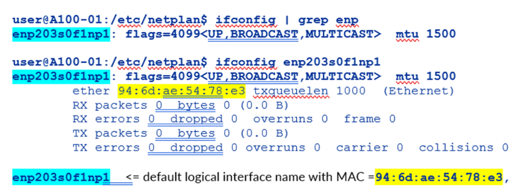
where:
en = ethernet network interface.
p203s0 = physical location of the network interface.
203 bus number.
s0 = slot number 0 on the bus.
f1 = function number 1 for the network interface.
np1 = Network Port 1
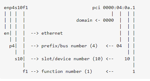
Function 0: Might be the primary Ethernet interface.
Function 1: Might be a second Ethernet interface.
Function 2: Might be a management or diagnostics interface.
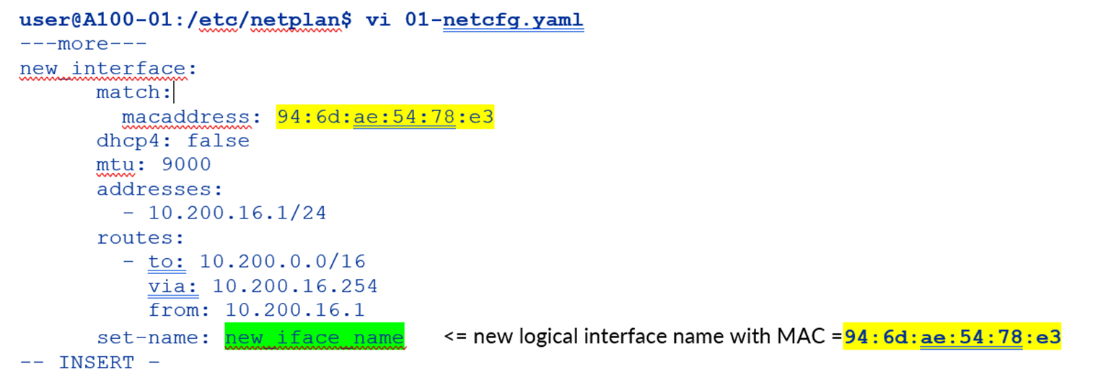
Figure 54. Nvidia A100 netplan file modification example
You can find the names of all the logical interfaces on the devnames file:
-
user@A100-01:/etc/network$ more devnames

enp139s0f0np0:Mellanox Technologies MT2910 Family [ConnectX-7]

enp139s0f1np1:Mellanox Technologies MT2910 Family [ConnectX-7]

enp142s0f0np0:Mellanox Technologies MT2910 Family [ConnectX-7]

enp142s0f1np1:Mellanox Technologies MT2910 Family [ConnectX-7]

enp14s0f0np0:Mellanox Technologies MT2910 Family [ConnectX-7]

enp14s0f1np1:Mellanox Technologies MT2910 Family [ConnectX-7]

enp17s0f0np0:Mellanox Technologies MT2910 Family [ConnectX-7]

enp17s0f1np1:Mellanox Technologies MT2910 Family [ConnectX-7]

enp200s0f0np0:Mellanox Technologies MT2910 Family [ConnectX-7]

enp200s0f1np1:Mellanox Technologies MT2910 Family [ConnectX-7]

enp203s0f0np0:Mellanox Technologies MT2910 Family [ConnectX-7]

enp203s0f1np1:Mellanox Technologies MT2910 Family [ConnectX-7]

enp44s0f0:Intel Corporation Ethernet Controller X710 for 10GBASE-T

enp44s0f1:Intel Corporation Ethernet Controller X710 for 10GBASE-T

enp44s0f2:Intel Corporation Ethernet Controller X710 for 10 Gigabit SFP+

enp44s0f3:Intel Corporation Ethernet Controller X710 for 10 Gigabit SFP+

enp81s0f0np0:Mellanox Technologies MT2910 Family [ConnectX-7]

enp81s0f1np1:Mellanox Technologies MT2910 Family [ConnectX-7]

enp82s0f0np0:Mellanox Technologies MT2910 Family [ConnectX-7]

enp82s0f1np1:Mellanox Technologies MT2910 Family [ConnectX-7]

ibp169s0f0:Mellanox Technologies MT28908 Family [ConnectX-6]

ibp169s0f1:Mellanox Technologies MT28908 Family [ConnectX-6]
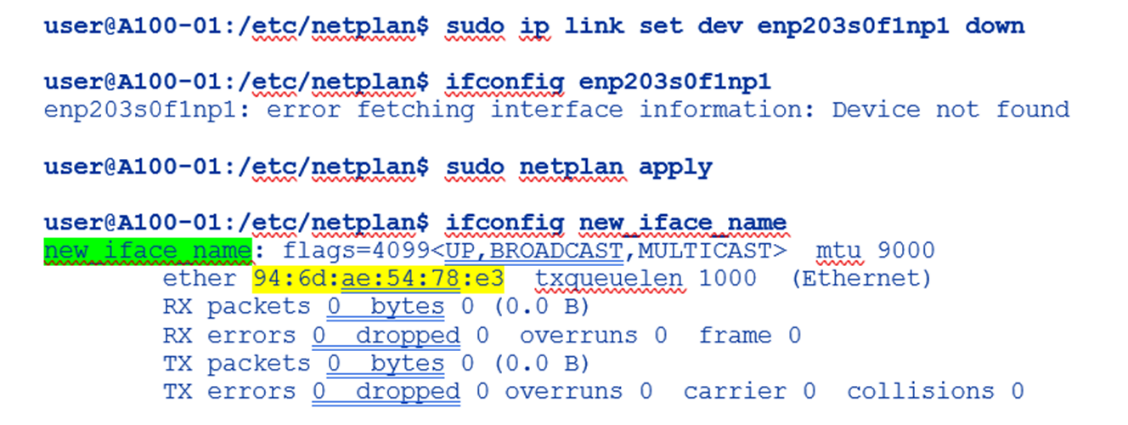
Apply the changes using the netplan apply command
Figure 55. Nvidia A100 netplan application example
To Change the NIC Name
Change the value of set-name in the configuration file and save the changes:
Figure 56. Nvidia A100 netplan interface name change example
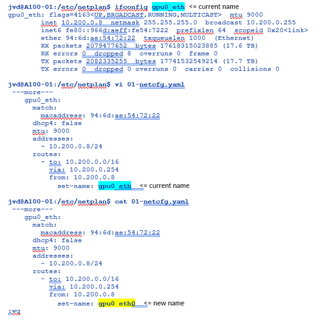
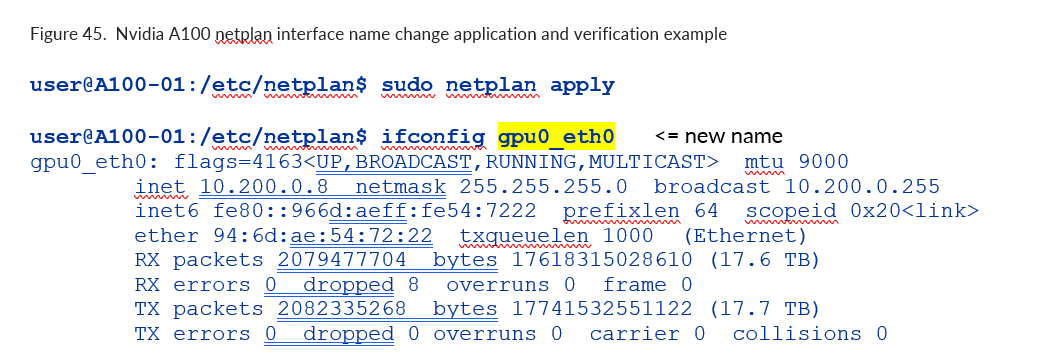
Apply the Changes Using the netplan apply command
Figure 57. Nvidia A100 netplan interface name change application and verification example
To Change the Current IP Address or Assign an IP Address to the NIC
Change or add the address under the proper interface in the configuration file, and save the changes:
Figure 58. Nvidia A100 netplan interface IP address change example
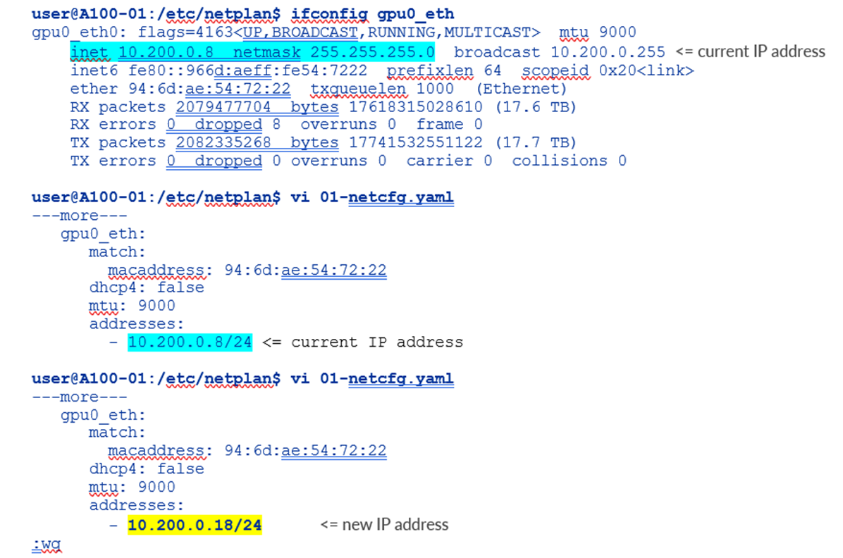
Enter the IP addresses preceded with a hyphen and indented; make sure to add the subnet mask.
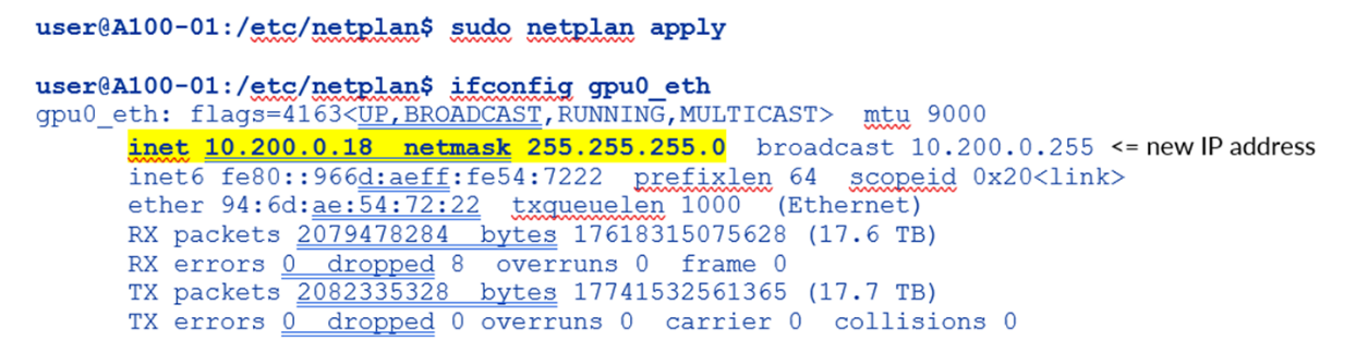
Apply the Changes Using the netplan apply Command
Figure 59. Nvidia A100 netplan interface new IP address application and verification example
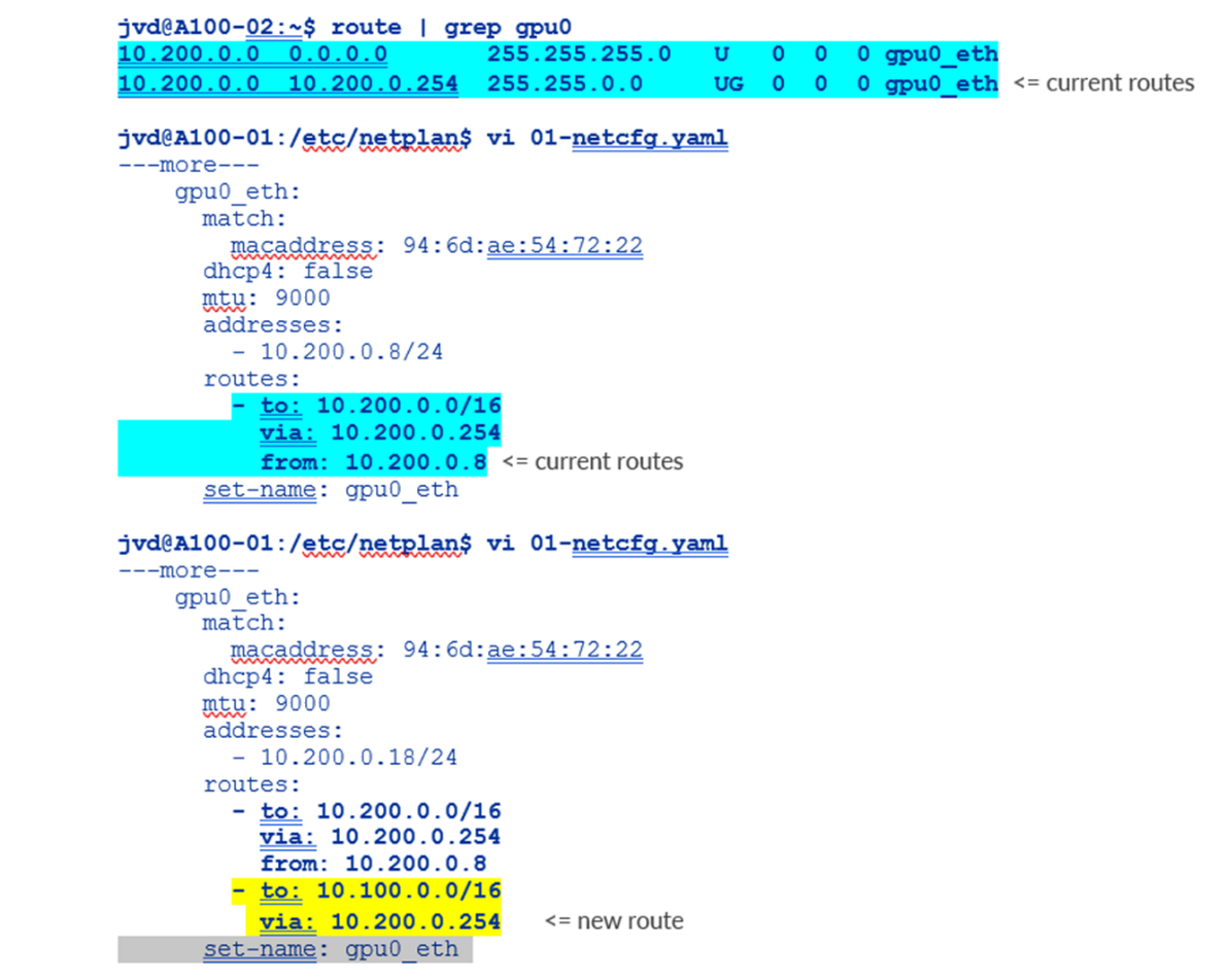
To Change or Add Routes to the NIC
Change or add the routes under the proper interface in the configuration file, and save the changes.
Figure 60. Nvidia A100 netplan additional routes example
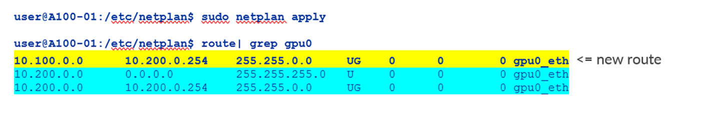
Apply the changes using the netplan apply command
Figure 61. Nvidia A100 netplan additional routes application and verification example:
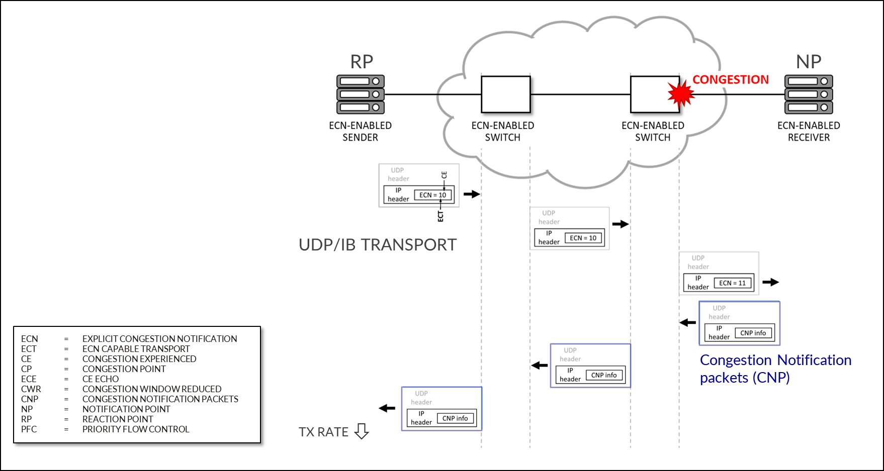
Configuring NVIDIA DCQCN – ECN
Figure 62: NVIDIA DCQCN – ECN
Starting from MLNX_OFED 4.1 ECN is enabled by default (in the firmware).
To confirm that ECN is enabled, use the following command: mlxconfig -d <device> q | grep ROCE_CC
Example:
-
root@A100-01:/home/ylara# mlxconfig -d mlx5_0 q | grep ROCE_CC

         ROCE_CC_PRIO_MASK_P1        255

         ROCE_CC_PRIO_MASK_P2        255
A mask of 255 means DCQCN (ECN) is enabled for all TC (traffic classes) configured on the NIC.
To disable ECN you can change the mask using the following command: mlxconfig -d <device> s ROCE_CC_PRIO_MASK_P1=<mask>
Example:
-
root@A100-01:/home/ylara# sudo mlxconfig -d mlx5_0 s ROCE_CC_PRIO_MASK_P1=0

Device #1:

----------

Device type:    ConnectX7

Name:           MCX755106AS-HEA_Ax

Description:    NVIDIA ConnectX-7 HHHL Adapter Card; 200GbE (default mode) / NDR200 IB; Dual-port QSFP112; PCIe 5.0 x16 with x16 PCIe extension option; Crypto Disabled; Secure Boot Enabled

Device:         mlx5_0

Configurations:                                      Next Boot       New

         ROCE_CC_PRIO_MASK_P1                        0               0

 Apply new Configuration? (y/n) [n] :
If you want to avoid being asked whether you want to apply the new configuration you an include the -y option as shown in the following example:
-
root@A100-01:/home/ylara# sudo mlxconfig -d mlx5_0 -y s ROCE_CC_PRIO_MASK_P1=0

Device #1:

----------

Device type:    ConnectX7

Name:           MCX755106AS-HEA_Ax

Description:    NVIDIA ConnectX-7 HHHL Adapter Card; 200GbE (default mode) / NDR200 IB; Dual-port QSFP112; PCIe 5.0 x16 with x16 PCIe extension option; Crypto Disabled; Secure Boot Enabled

Device:         mlx5_0

Configurations:                                      Next Boot       New

         ROCE_CC_PRIO_MASK_P1                        0               0

 Apply new Configuration? (y/n) [n] : y

Applying... Done!

-I- Please reboot machine to load new configurations.
The output states that a server reboot is required. As an alternative, you can reset the interface using the command: mlxfwreset -d <device> -l 3 -y r.
Example:
-
root@A100-01:/home/ylara# mlxfwreset -d mlx5_0 -l 3 -y r

Requested reset level for device, /dev/mst/mt4129_pciconf2:

3: Driver restart and PCI reset

Continue with reset?[y/N] y

-I- Sending Reset Command To Fw             -Done

-I- Stopping Driver                         -Done

-I- Resetting PCI                           -Done

-I- Starting Driver                         -Done

-I- Restarting MST                          -Done

-I- FW was loaded successfully.
ECN operations parameters are located on the following path /sys/class/net/<interface>/ecn
Use the following command to find the interface:
-
jvd@A100-01:~/$ ls /sys/class/net/

docker0   enp14s0f1np1 enp17s0f1np1 enp44s0f1np1  gpu0_eth  gpu3_eth  gpu6_eth mgmt_eth

enp139s0f1np1 enp169s0f0np0 enp200s0f1np1 enp81s0f1np1 gpu1_eth gpu4_eth gpu7_eth usb0

enp142s0f1np1 enp169s0f1np1 enp203s0f1np1 enp82s0f1np1 gpu2_eth gpu5_eth lo

jvd@A100-01:/sys/class/net/gpu0_eth/ecn$ ls

roce_np  roce_rp
Notification Point (NP) Parameters
When the ECN-enabled receiver receives ECN-marked RoCE packets, it responds by sending CNP (Congestion Notification Packets).
The following commands describe the notification parameters:
-
jvd@A100-01:/sys/class/net/gpu0_eth/ecn$ ls /roce_np/

cnp_802p_prio  cnp_dscp  enable  min_time_between_cnps
Examples:
-
jvd@A100-01:/sys/class/net/gpu0_eth/ecn$ cat roce_np/cnp_802p_prio

6
cnp_802p_prio = the value of the PCP (Priority Code Point) field of the CNP packets.
PCP is a 3-bit field within an Ethernet frame header when using VLAN tagged frames as defined by IEEE 802.1Q.
-
jvd@A100-01:/sys/class/net/gpu0_eth/ecn$ cat roce_np/cnp_dscp

48
cnp_dscp = the value of the DSCP (Differentiated Services Code Point) field of the CNP packets.
-
jvd@A100-01:/sys/class/net/gpu0_eth/ecn$ cat roce_np/min_time_between_cnps

4
min_time_between_cnps = minimal time between two consecutive CNPs sent. if ECN-marked RoCE packet arrives in a period smaller than min_time_between_cnps since previous sent CNP, no CNP will be sent as a response. This value is in microseconds. Default = 0
-
jvd@A100-01:/sys/class/net/gpu0_eth/ecn$ cat roce_np/enable/*

1

1

1

1

1

1

1

1
The output shows that roce_np is enabled for all priority values.
To change the attributes described above, use the mlxconfig utility:
-
mlxconfig -d /dev/mst/<mst_module> -y s CNP_DSCP_P1=<value> CNP_802P_PRIO_P1=<value>
Example:
-
jvd@A100-01:/dev/mst$ sudo mst start

Starting MST (Mellanox Software Tools) driver set

Loading MST PCI module - Success

[warn] mst_pciconf is already loaded, skipping

Create devices

Unloading MST PCI module (unused) – Success

jvd@A100-01:~/scripts$ ./map_full_mellanox.sh


Mellanox Device to mlx and Network Interface Mapping:

/dev/mst/mt4123_pciconf0 => mlx5_14 => enp169s0f0np0 (0000:a9:00.0)

/dev/mst/mt4125_pciconf0 => mlx5_4 => mgmt_eth (0000:2c:00.0)

/dev/mst/
                mt4129_pciconf0
               => mlx5_6 => gpu0_eth (0000:0e:00.0)

/dev/mst/mt4129_pciconf1 => mlx5_8 => gpu1_eth (0000:11:00.0)

/dev/mst/mt4129_pciconf2 => mlx5_0 => gpu2_eth (0000:51:00.0)

/dev/mst/mt4129_pciconf3 => mlx5_2 => gpu3_eth (0000:52:00.0)

/dev/mst/mt4129_pciconf4 => mlx5_16 => gpu4_eth (0000:8b:00.0)

/dev/mst/mt4129_pciconf5 => mlx5_18 => gpu5_eth (0000:8e:00.0)

/dev/mst/mt4129_pciconf6 => mlx5_10 => gpu7_eth (0000:c8:00.0)

/dev/mst/mt4129_pciconf7 => mlx5_12 => gpu6_eth (0000:cb:00.0)

jvd@A100-01:/sys/class/net/gpu0_eth/ecn$ sudo mlxconfig -d /dev/mst/
                mt4129_pciconf0
               -y set CNP_DSCP_P1=40 CNP_802P_PRIO_P1=7

Device #1:

----------

Device type:        ConnectX7

Name:               MCX755106AS-HEA_Ax

Description:        NVIDIA ConnectX-7 HHHL Adapter Card; 200GbE (default mode) / NDR200 IB; Dual-port QSFP112; PCIe 5.0 x16 with x16 PCIe extension option; Crypto Disabled; Secure Boot Enabled

Device:             /dev/mst/mt4129_pciconf0

Configurations:                                          Next Boot       New

        CNP_DSCP_P1                                 48                   40

        CNP_802P_PRIO_P1                            6                    7

Apply new Configuration? (y/n) [n] : y

Applying... Done!

-I- Please reboot machine to load new configurations.
Reaction Point (RP) Parameters
When the ECN-enabled sender receives CNP packets, it responds by slowing down transmission for the specified flows (priority).
The following parameters define how traffic flows will be rate limited, after CNP packets arrival:
-
jvd@A100-01:/sys/class/net$ ls gpu0_eth/ecn/roce_rp/

clamp_tgt_rate  enable  rpg_ai_rate     rpg_max_rate    rpg_time_reset

clamp_tgt_rate_after_time_inc   initial_alpha_value     rpg_byte_reset  rpg_min_dec_fac

dce_tcp_g               rate_reduce_monitor_period              rpg_gd

rpg_min_rate            dce_tcp_rtt     rate_to_set_on_first_cnp

rpg_hai_rate                    rpg_threshold
Examples:
-
jvd@A100-01:/sys/class/net/gpu0_eth/ecn$ cat roce_rp/enable/*

1

1

1

1

1

1

1

1

jvd@A100-01:/sys/class/net/gpu0_eth/ecn$ cat roce_rp/rpg_max_rate

0
rpg_max_rate = Maximum rate at which reaction point node can transmit. Once this limit is reached, RP is no longer rate limited.
This value is configured in Mbits/sec. Default = 0 (full speed – no max)
The output shows that roce_rp is enabled for all priority values.
To check the ECN statistics use: ethtool -S <interface> | grep ecn
Example:
-
jvd@A100-01:~/scripts$ ethtool -S gpu0_eth | grep ecn

     rx_ecn_mark: 0

     rx_xsk_ecn_mark: 0

     rx0_ecn_mark: 0

     rx1_ecn_mark: 0

     rx2_ecn_mark: 0

     rx3_ecn_mark: 0

     rx4_ecn_mark: 0

     rx5_ecn_mark: 0

     rx6_ecn_mark: 0

     rx7_ecn_mark: 0

     rx8_ecn_mark: 0

 ---more---
NVIDIA DCQCN – PFC Configuration
IEEE 802.1Qbb applies pause functionality to specific classes of traffic on the Ethernet link.
Figure 63: NVIDIA DCQCN – PFC Configuration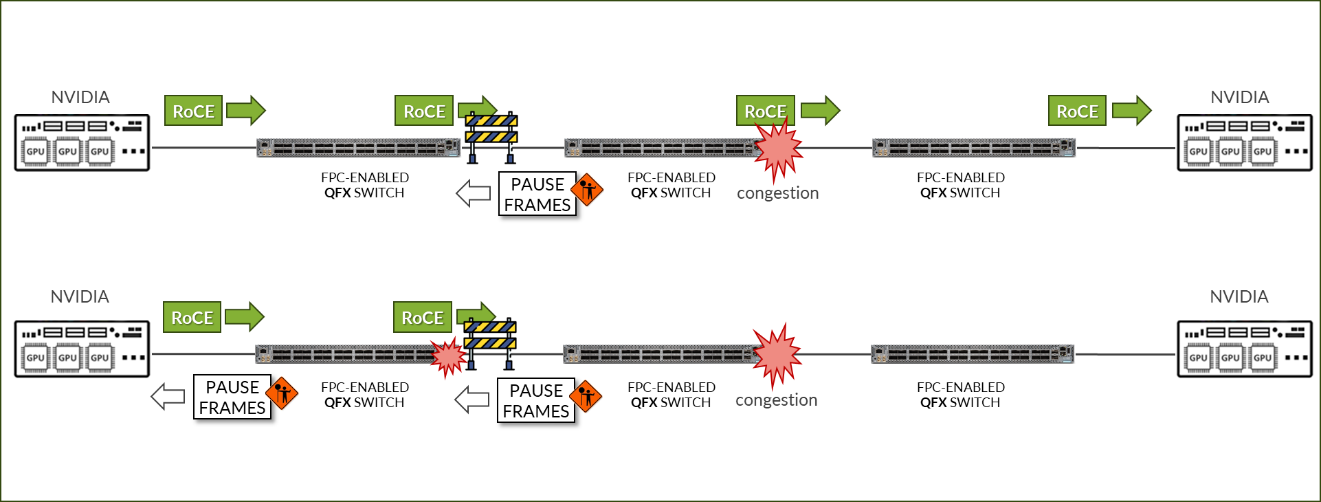
To check whether PFC is enabled on an interface use: mlnx_qos -i <interface>
Example:
-
jvd@A100-01:/sys/class/net/gpu0_eth/ecn$ sudo mlnx_qos -i gpu0_eth

DCBX mode: OS controlled

Priority trust state: dscp

dscp2prio mapping:

        prio:0 dscp:07,06,05,04,03,02,01,00,

        prio:1 dscp:15,14,13,12,11,10,09,08,

        prio:2 dscp:23,22,21,20,19,18,17,16,

        prio:3 dscp:31,30,29,28,27,26,25,24,

        prio:4 dscp:39,38,37,36,35,34,33,32,

        prio:5 dscp:47,46,45,44,43,42,41,40,

        prio:6 dscp:55,54,53,52,51,50,49,48,

        prio:7 dscp:63,62,61,60,59,58,57,56,

default priority:

Receive buffer size (bytes): 19872,243072,0,0,0,0,0,0,max_buffer_size=2069280

Cable len: 7


                PFC configuration
              :

        priority    0   1   2
                3
                 4   5   6   7

        enabled     0   0   0
                1
                 0   0   0   0

        buffer      0   0   0
                1
                 0   0   0   0

tc: 0 ratelimit: unlimited, tsa: vendor

         priority:  1

tc: 1 ratelimit: unlimited, tsa: vendor

         priority:  0

tc: 2 ratelimit: unlimited, tsa: vendor

         priority:  2

tc: 3 ratelimit: unlimited, tsa: vendor

         priority:  3

tc: 4 ratelimit: unlimited, tsa: vendor

         priority:  4

tc: 5 ratelimit: unlimited, tsa: vendor

         priority:  5

tc: 6 ratelimit: unlimited, tsa: vendor

         priority:  6

tc: 7 ratelimit: unlimited, tsa: vendor

         priority:  7
To enable/disable PFC use: mlnx_qos -i <interface> --pfc <0/1>,<0/1>,<0/1>,<0/1>,<0/1>,<0/1>,<0/1>,<0/1>
Example:
- Check the current configuration:
-
jvd@A100-01:/sys/class/net/gpu0_eth/ecn$ sudo mlnx_qos -i gpu0_eth

DCBX mode: OS controlled

Priority trust state: dscp

dscp2prio mapping:

        prio:0 dscp:07,06,05,04,03,02,01,00,

        prio:1 dscp:15,14,13,12,11,10,09,08,

        prio:2 dscp:23,22,21,20,19,18,17,16,

        prio:3 dscp:31,30,29,28,27,26,25,24,

        prio:4 dscp:39,38,37,36,35,34,33,32,

        prio:5 dscp:47,46,45,44,43,42,41,40,

        prio:6 dscp:55,54,53,52,51,50,49,48,

        prio:7 dscp:63,62,61,60,59,58,57,56,

default priority:

Receive buffer size (bytes): 19872,243072,0,0,0,0,0,0,max_buffer_size=2069280

Cable len: 7


                PFC configuration
              :

        priority    0   1   2
                3
                 4   5   6   7

        enabled     0   0   0
                1
                 0   0   0   0

        buffer      0   0   0
                1
                 0   0   0   0

---more---
The output in the example, indicates that PFC is enable for Priority 3.
- Enable PFC for priority 2 and disable PFC for priority 3:
-
jvd@A100-01:~/scripts$ sudo mlnx_qos -i gpu0_eth --pfc 0,0, 1 ,0,0,0,0,0 DCBX mode: OS controlled Priority trust state: dscp dscp2prio mapping: prio:0 dscp:07,06,05,04,03,02,01,00, prio:1 dscp:15,14,13,12,11,10,09,08, prio:2 dscp:23,22,21,20,19,18,17,16, prio:3 dscp:31,30,29,28,27,26,25,24, prio:4 dscp:39,38,37,36,35,34,33,32, prio:5 dscp:47,46,45,44,43,42,41,40, prio:6 dscp:55,54,53,52,51,50,49,48, prio:7 dscp:63,62,61,60,59,58,57,56, default priority: Receive buffer size (bytes): 19872,243072,0,0,0,0,0,0,max_buffer_size=2069280 Cable len: 7 PFC configuration: priority 0 1 2 3 4 5 6 7 enabled 0 0 1 0 0 0 0 0 buffer 0 0 1 0 0 0 0 0 ---more--- - Check PFC statistics:
jvd@A100-01:~/scripts$ ethtool -S gpu0_eth | grep pause

     rx_pause_ctrl_phy: 8143294

     tx_pause_ctrl_phy: 502


                rx_prio3
              _pause: 8143294


                rx_prio3
              _pause_duration: 10848932


                tx_prio3
              _pause: 502


                tx_prio3
              _pause_duration: 30445


                rx_prio3
              _pause_transition: 4071126

     tx_pause_storm_warning_events: 0

     tx_pause_storm_error_events: 0
NVIDIA TOS/DSCP Configuration for RDMA-CM QPS (RDMA Traffic)
Figure 64: NVIDIA TOS/DSCP
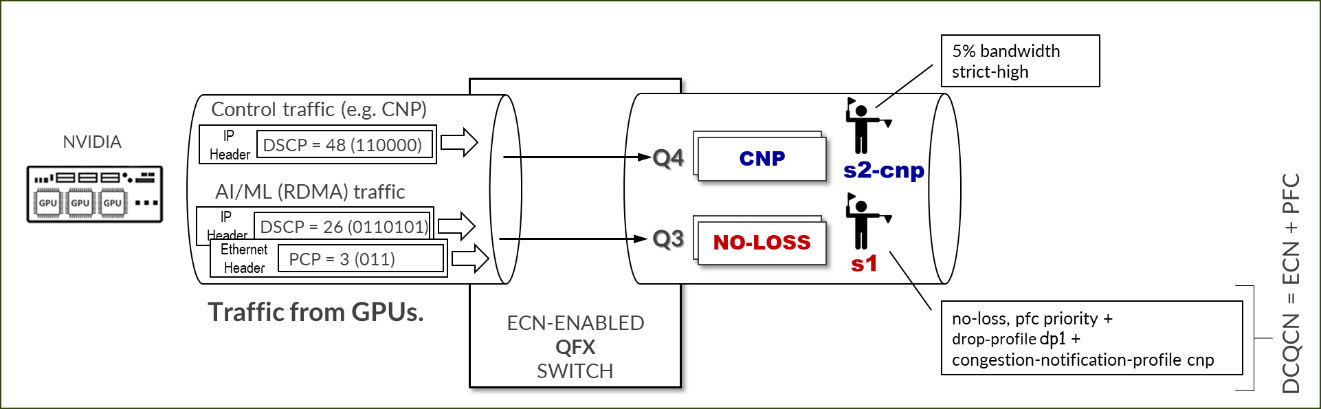
RDMA traffic must be properly marked to allow the switch to correctly classify it, and to place it in the lossless queue for proper treatment. Marking can be either DSCP within the IP header, or PCP in the ethernet frame vlan-tag field. Whether DSCP or PCP is used depends on whether the interface between the GPU server and the switch is doing vlan tagging (802.1q) or not.
To check the current configuration and to change the values of TOS for the RDMA outbound traffic, use the cma_roce_tos script that is part of MLNX_OFED 4.0.
-
jvd@A100-01:/sys/class/net/gpu0_eth/ecn$ sudo cma_roce_tos -h

Set/Show RoCE default TOS of RDMA_CM applications

Usage:

        cma_roce_tos OPTIONS

Options:

        -h              show this help

        -d <dev>        use IB device <dev> (default mlx5_0)

        -p <port>       use port <port> of IB device (default 1)

        -t <TOS>        set TOS of RoCE RDMA_CM applications (0)
To check the current value of the TOS field enter sudo cma_roce_tos without any options.
Example:
-
jvd@A100-01:/sys/class/net/gpu0_eth/ecn$ sudo cma_roce_tos

106
In the example, the current TOS value = 106, which means a DSCP value = 48 and the ECN bits set to 10.
To change the value use: cma_roce_tos –d <ib_device> -t <TOS>
You need to enter the ib_device in this command. The following script automatically does the mapping between the physical interfaces and the ib_device.
-
map_full_mellanox.sh

#!/bin/bash

# Script to map Mellanox devices to mlx and network interfaces

# Get Mellanox device PCI addresses

mst_status=$(sudo mst status | awk '

/\/dev\/mst/ {

    dev = $1

}

/domain:bus:dev.fn/ {

    pci = $1

    printf "%s: %s\n", dev, pci

}

')

# Get network interface PCI addresses

iface_status=$(for iface in $(ls /sys/class/net/); do

    pci_addr=$(ethtool -i $iface 2>/dev/null | grep bus-info | awk '{print $2}')

    if [ ! -z "$pci_addr" ]; then

        echo "$iface: $pci_addr"

    fi

done)

# Get network interface to mlx interface mapping

mlx_iface_status=$(for iface in $(ls /sys/class/net/); do

    if [ -d /sys/class/net/$iface/device/infiniband_verbs ]; then

        mlx_iface=$(cat /sys/class/net/$iface/device/infiniband_verbs/*/ibdev)

        echo "$iface: $mlx_iface"

    fi

done)

# Combine and print the mapping

echo "Mellanox Device to mlx and Network Interface Mapping:"

echo "$mst_status" | while read -r mst_line; do

    mst_dev=$(echo $mst_line | awk -F ': ' '{print $1}')

    mst_pci=$(echo $mst_line | awk -F '=| ' '{print $3}')

    iface=$(echo "$iface_status" | grep $mst_pci | awk -F ': ' '{print $1}')

    iface_pci=$(echo "$iface_status" | grep $mst_pci | awk -F ': ' '{print $2}')

    mlx_iface=$(echo "$mlx_iface_status" | grep $iface | awk -F ': ' '{print $2}')

    if [ ! -z "$iface" ] && [ ! -z "$mlx_iface" ]; then

        echo "$mst_dev => $mlx_iface => $iface ($iface_pci)"

    fi

done
Example:
Figure 65. script results example

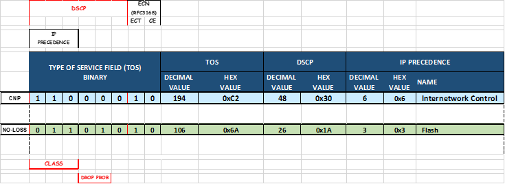
Figure 66. Reference TOS, DSCP Mappings:

Configuring NVIDIA to Use the Management Interface for NCCL Control Traffic
NCCL uses TCP sessions to connect processes together and exchange QP information for RoCE, GIDs (Global IDs), Local and remote buffer addresses, RDMA keys (RKEYs for memory access permissions)
These sessions are created when the job starts and by default use one of the GPU interfaces (same interfaces used for RoCEv2 traffic).
Example:
-
ylara@A100-01:~$ netstat -atn | grep 10.200 | grep "ESTABLISHED"

tcp        0      0 10.200.4.8:47932        10.200.4.2:43131        ESTABLISHED

tcp        0      0 10.200.4.8:46699        10.200.4.2:37236        ESTABLISHED

tcp        0      0 10.200.2.8:60502        10.200.13.2:35547       ESTABLISHED

tcp        0      0 10.200.4.8:37330        10.200.4.2:55355        ESTABLISHED

tcp        0      0 10.200.4.8:56438        10.200.4.2:53947        ESTABLISHED

---more---
It is recommended, move to the management interface (connected to the (Frontend Fabric) including the following parameter when starting a job: export NCCL_SOCKET_IFNAME="mgmt_eth"
Example:
-
ylara@A100-01:~$ netstat -atn | grep 10.10.1 | grep "ESTABLISHED"

tcp        0      0 10.10.1.0:44926         10.10.1.2:33149         ESTABLISHED

tcp        0      0 10.10.1.0:46705         10.10.1.0:40320         ESTABLISHED

tcp        0      0 10.10.1.0:54661         10.10.1.10:52452        ESTABLISHED

---more---