High Availability Design for Session Smart Routers
Juniper® Networks Session Smart™ High Availability (HA) Design Guide is for administrators who want to deploy HA Juniper Session Smart Routers at the Edge, but not for Whitebox setups.
In this documentation you’ll find step-by-step guidance for setting up a highly available hub and spoke deployment using Juniper® Mist WAN Assurance. Since this HA deployment builds upon the topology referenced in the Juniper Session Smart WAN Assurance Configuration Guide, you'll need to configure your network with that topology first. Building upon the reference topology in the Juniper Session Smart WAN Assurance Configuration Guide, you'll learn how to setup Session Smart Routers in an HA cluster configuration.
Devices in an HA pair must be identical. An HA pair with two SSR120s will work. An HA pair with one SSR120 and one SSR102-AE will not work.
Overview
You will deploy a highly available Hub and Spoke as shown in Figure 1. Here we see the Session Smart highly available Juniper Mist WAN Assurance topology for this HA Design Guide.
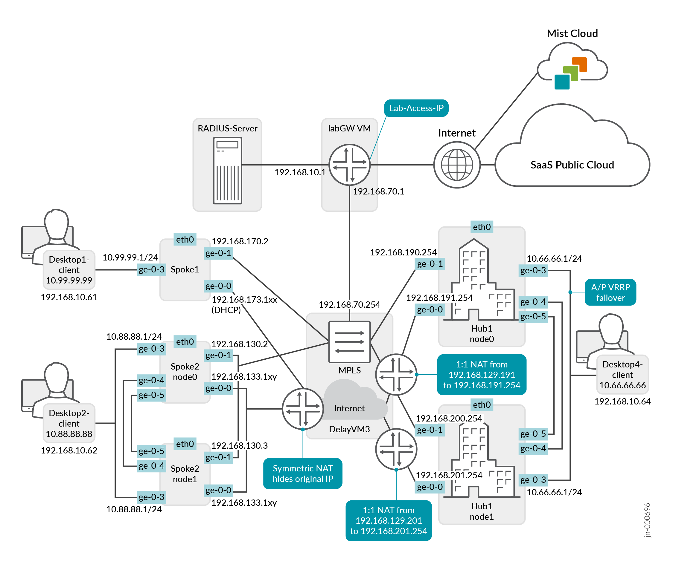
Before you get started, be sure you’ve setup the topology described in the Juniper WAN Assurance Configuration Guide.
Interfaces
The Interfaces use the following pattern for each node:
Node0: ge-0/0/x
Node1: ge-1/0/x
WAN Interfaces for HA hubs require static IP addresses. Spokes reach out across the overlay to these WAN interface endpoints.
HA Interfaces
Each path and Node in an HA network require their own designated WAN interface. This ensures active/active usage, meaning that these interfaces stay active and engaged, no matter what. WAN interfaces on spoke devices can contain either a static IP address or be linked to a DHCP-lease, giving you flexibility in how you manage them.
In certain scenarios, you may be limited to just one WAN IP address, especially for MPLS Networks. In these cases, you can configure the interface as a shared VRRP interface between two Nodes. This sets up an active/passive usage of the links, maintaining the balance and ensuring continuity. A second IP address for that second node enhances your setup's performance even further.
LAN Interfaces
You’ll need to define the LAN interfaces for both HA hubs and spokes are as redundant interfaces, and then specify the interfaces together as ge-0/0/x, ge-1/0/x. This will make them VRRP Interfaces.
Redundant VRRP Interfaces are only Active/Passive, meaning only the currently active Session Smart Router interface will broadcast VRRP.
The redundant VRRP interfaces must be in the same Layer 2 domain and need a single static IP address. The Active/Passive Interfaces will have a shared MAC address. Based on the device, the system decides who will be node0 and who will be node1.
- The lowest MAC address will be selected for node0.
- For Redundant VRRP interfaces, you can define which node is the primary, but we recommend leaving the default to node0 for consistency.
It's important to be aware of the two specific Ethernet interfaces that handle HA synchronization and fabric data exchange on the supported devices. See the Session Smart documentation https://www.juniper.net/documentation/us/en/software/session-smart-router/docs/concepts_ha_theoryofoperation.
The HA synchronization link ensures that the two devices are chronologically synchronized and can swap appropriately in the event of an interface or device failure. The synchronization interface serves as the back-or-midplane of a chassis-based router.
The fabric interface is a forwarding interface between two nodes in a router and is used when the ingress interface and egress interface for a given session are active on different nodes. The synchronization and fabric interfaces are usually the two last ports of the system. You must wire them back-to-back with direct patch cables.
Configure High Availability
The following steps outline the process of adding the HA Hub Site.
To add a highly available hub we’ll need to create the first HA Site for the redundant interfaces. Later, we’ll clone this one for redundancy. Remember this HA Node will be the first device in a pair for path failover in the event of an issue or failure.
You should have already configured Networks, Applications, Sites, Variables, Hub Profiles and WAN Edge Templates. If these steps are new to you, please follow the Mist WAN Configuration Guide first before proceeding with the HA design guide. See WAN Assurance Configuration Overview.
-
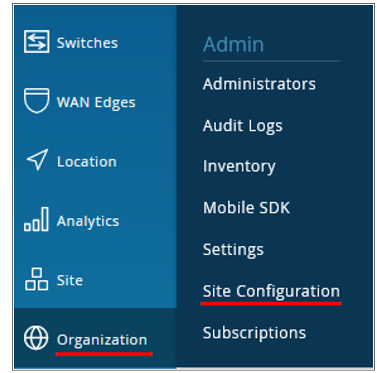
In the Juniper Mist™ portal, click Organization >
Admin > Site
Configuration..
Figure 2: Site Configuration
 A list of existing sites, if any, appears.
 -
Click Create Site in the upper right corner. The New
Site window appears.
- Give the site a name. In this example, name the site as hahub-site.
- Add a location for your site
- Scroll down the page to the Switch Management
and WAN Edge Management settings pane, and
configure the root password. Figure 3: Configure Root Password
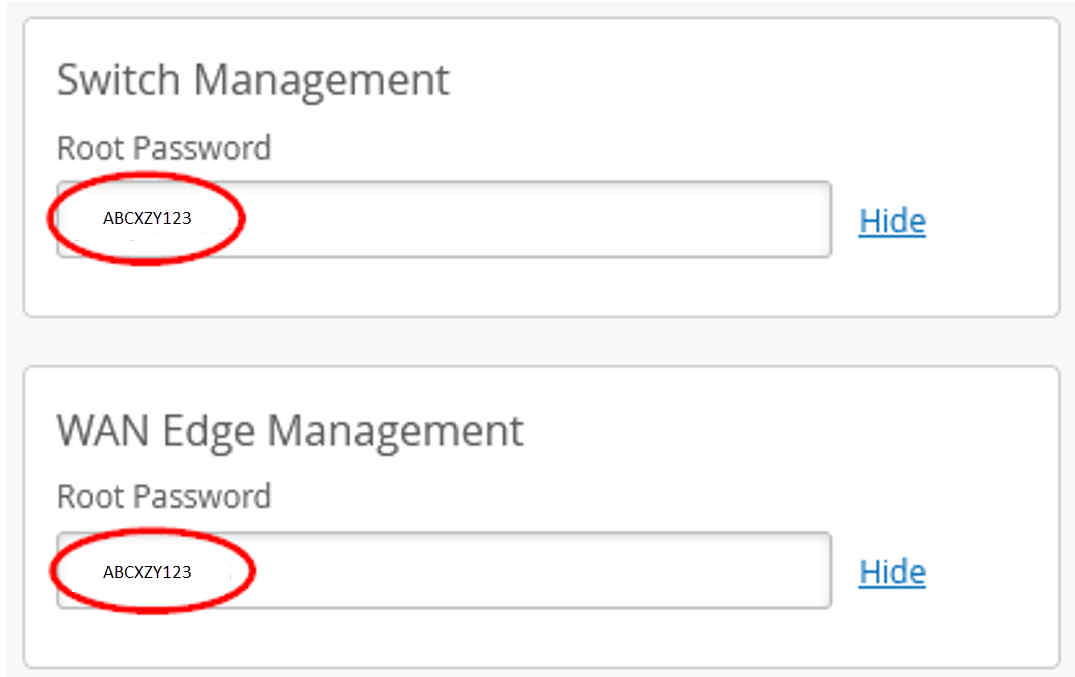
When you activate a device to be managed by Mist Cloud, it will set a random root password for security if you don’t define it.
-
Define a LAN interface with the following variables. When you define a LAN
interface, the variables on the hahub-site merge with the existing hub1-site
and hub2-site.
Remember, the whole purpose of Site Variables is to provide simplicity and flexibility for deployment at a large scale. When you attach the template to different sites, Juniper Mist cloud uses the appropriate IP address automatically in each site when the configuration is rendered and pushed to the device.
Use Table 1 to complete the list of variables you need to add.
Table 1: Variable Settings for Sites Site Name Variable Value hahub-site {{HAHUB_LAN1_PFX}} 10.66.66 hahub-site {{HAHUB_LAN1_VLAN}} 1066 hahub-site {{N0_WAN0_PFX}} 192.168.191 hahub-site {{N0_WAN1_PFX}} 192.168.190 hahub-site {{N0_WAN0_PUBIP}} 192.168.129.191 hahub-site {{N0_WAN1_PUBIP}} 192.168.190.254 hahub-site {{N1_WAN0_PFX}} 192.168.201 hahub-site {{N1_WAN1_PFX}} 192.168.200 hahub-site {{N1_WAN0_PUBIP}} 192.168.129.201 <hahub-site {{N1_WAN1_PUBIP}} 192.168.200.254 Figure 4shows the list of newly created variables.
Figure 4: Site Variables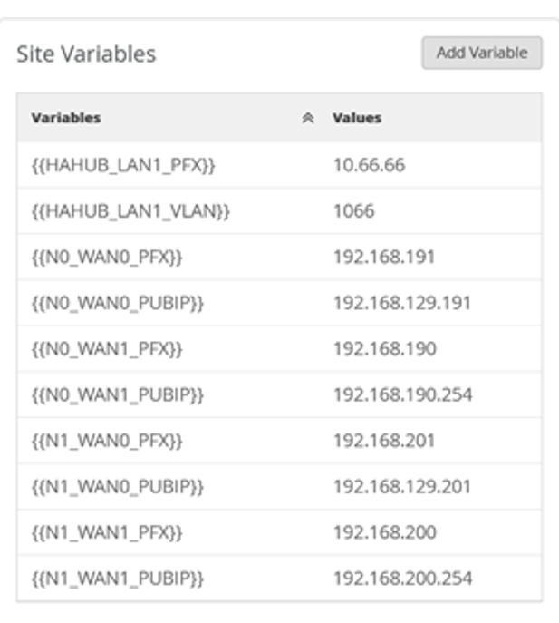
-
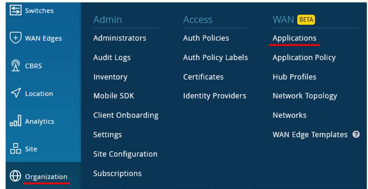
In the Juniper Mist portal, click Organization >
WAN>
Applications.
Figure 5: Add Applications
 A list of existing applications, if any, appears.
 -
Configure a match for all IP addresses attached at the LAN interface of the
HA hub site.
Configure the following items:
- Name—HAHUB-LAN1
- IP addresses—Configure the single IP prefix 10.66.66.0/24 for now.
Figure 6: Configure Applications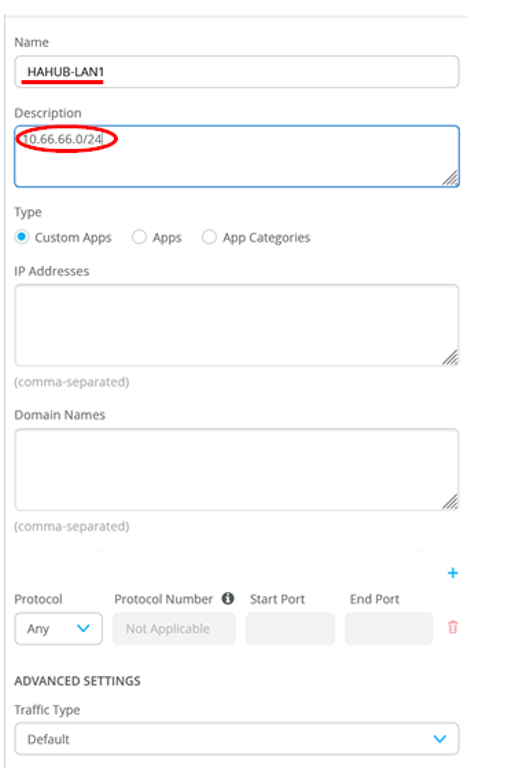
Figure 7 shows the application you created under applications list.
Figure 7: Applications List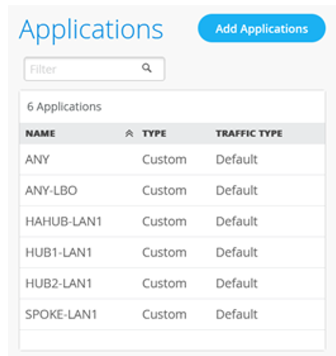
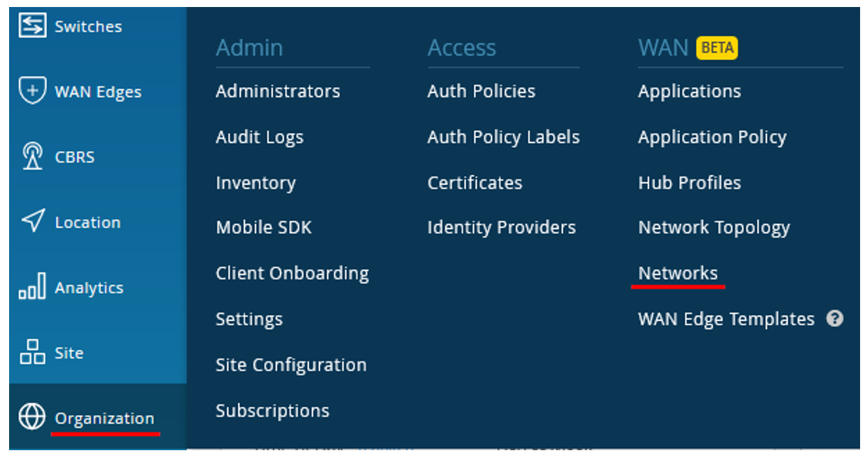
-
In the Juniper Mist cloud portal, click Organization
> WAN > Networks.
Figure 8: Configure Traffic Source
A list of existing networks, if any, appears.
-
Configure the options for the traffic source.
Figure 9: Configure Network (Traffic Source)
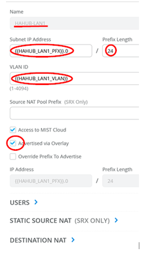
- Name: HAHUB-LAN1
- Subnet IP Address: {{HAHUB_LAN1_PFX}}.0. This value substitutes via site variables that contain the first three octets.)
- Prefix Length: 24 (Hardcoded)
- VLAN ID: {{HAHUB_LAN1_VLAN}} (For automatic tagging via site variable.)
- Check Access to Mist Cloud. For possible future device management by the Mist Cloud with the correct policies.
- Check Advertised via Overlay. This option creates the endpoints for spoke communication across the WAN.
Figure 10 shows the network you created under Networks list.
Figure 10: Networks List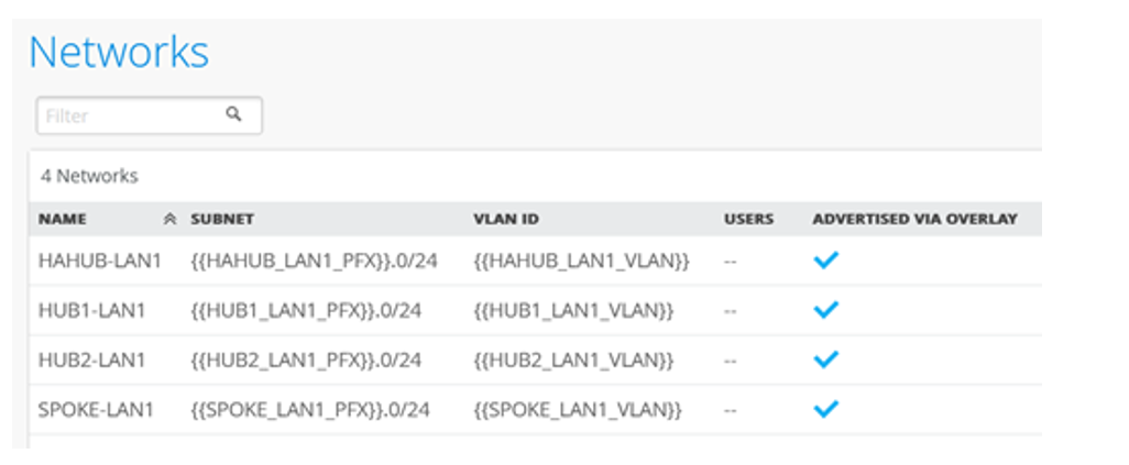 Note:
Note:Note: Networks are the sources of your traffic, the “who” in the Mist paradigm. Here we’re telling our Hub where the traffic requests will come from. This is the second part of the intent driven Mist expression bringing the “who” to the “what”.
Create a New Hub Profile
Now it’s time to add the second Node in your highly available Hub. In this next step, you’ll create a new Hub profile by cloning the existing one. Then, you’ll modify the clone to meet new requirements for the HA hub.
-
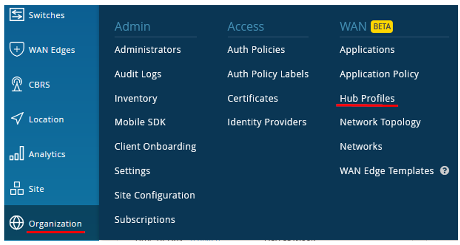
In the Juniper Mist cloud portal, click Organization
> WAN > Hub
Profiles.
Figure 11: Configure Hub Profiles
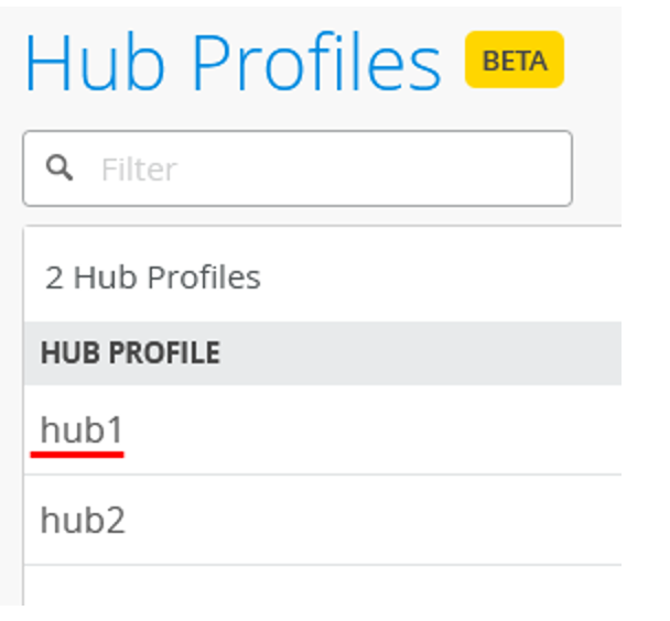
A list of existing hub profiles, if any, appears.
-
Click the hub profile ( hub1) that you want to clone.
Figure 12: Select Hub Profile for Cloning
-
In the upper right corner of the screen, click More
and select Clone.
Figure 13: Selecting Clone Option

-
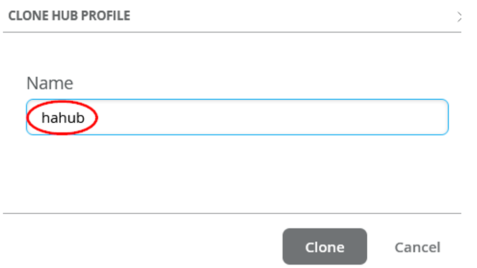
Name the new profile ( hahub.) and click
Clone.
Figure 14: Rename Cloned Hub Profile
 Note:
Note:After you clone, refresh your browser. This makes sure everything updates properly.
-
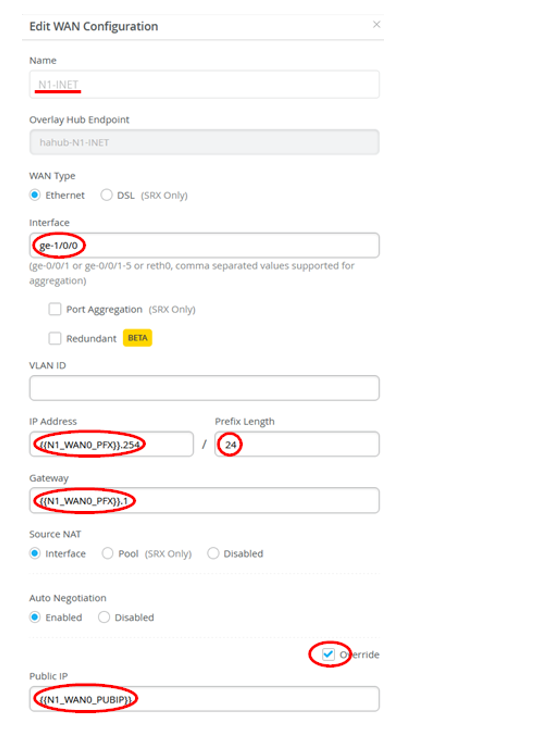
Modify the new profile and create four new WAN interfaces. Delete the
existing WAN interfaces from the clone and configure the WAN interfaces
according to the details provided in Table 2.
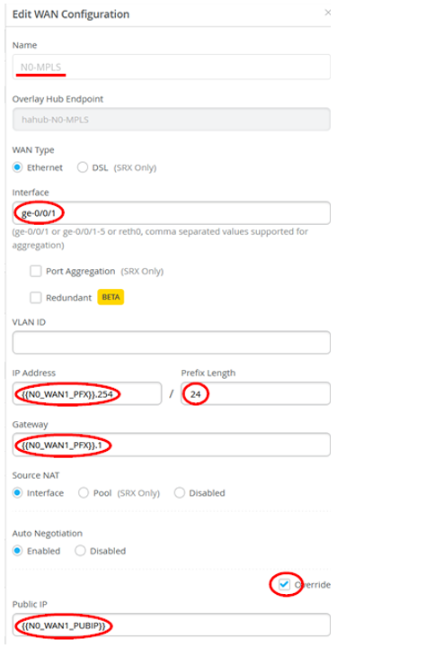
Table 2: WAN Interfaces Details in Hub Profile Option First WAN Second WAN Third WAN Fourth WAN Name: (This indicates which topology it uses.) N0-INET (Overlay endpoint: hahub-N0-INET (automatically generated)
)N0-MPLS (Overlay endpoint: hahub-N0-MPLS (automatically generated)
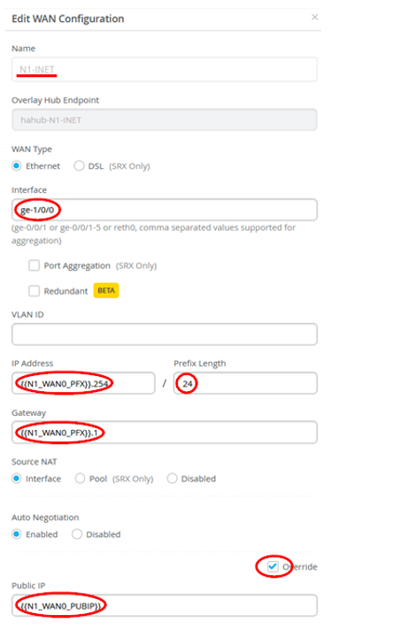
N1-INET (Overlay endpoint: hahub-N1-INET (automatically generated)
N1-MPLS (Overlay endpoint: hahub-N1-MPLS (automatically generated)
Interface ge-0/0/0 ge-0/0/1 ge-1/0/0 ge-1/0/1 IP Address: {{N0_WAN0_PFX}}.254 {{N0_WAN1_PFX}}.254 {{N1_WAN0_PFX}}.254 {{N1_WAN1_PFX}}.254 Prefix Length: 24 24 24 24 Gateway: {{N0_WAN0_PFX}}.1 {{N0_WAN1_PFX}}.1 {{N1_WAN0_PFX}}.1 {{N1_WAN1_PFX}}.1 Source NAT: Enabled Enabled Enabled Enabled Check Override for Public IP Yes Yes Yes Yes Public IP: {{N0_WAN0_PUBIP}} {{N0_WAN1_PUBIP}} {{N1_WAN0_PUBIP}} {{N1_WAN1_PUBIP}} Figure 15 shows WAN interface configuration.
Figure 15: WAN Interface Configuration (First)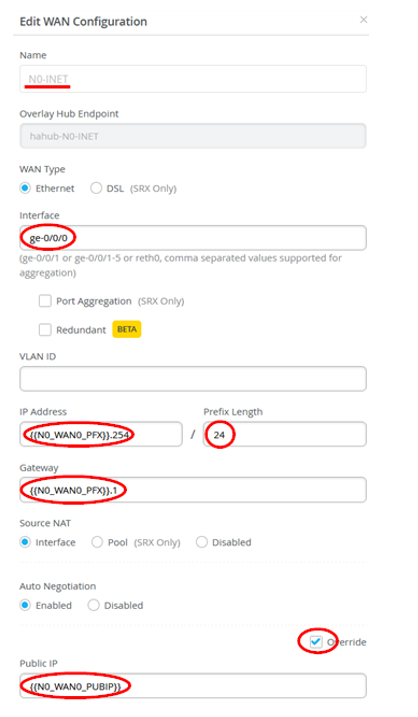
The WAN interfaces for each node should look as shown in Figure 16.
Figure 16: List of WAN Interfaces Configured in Hub Profile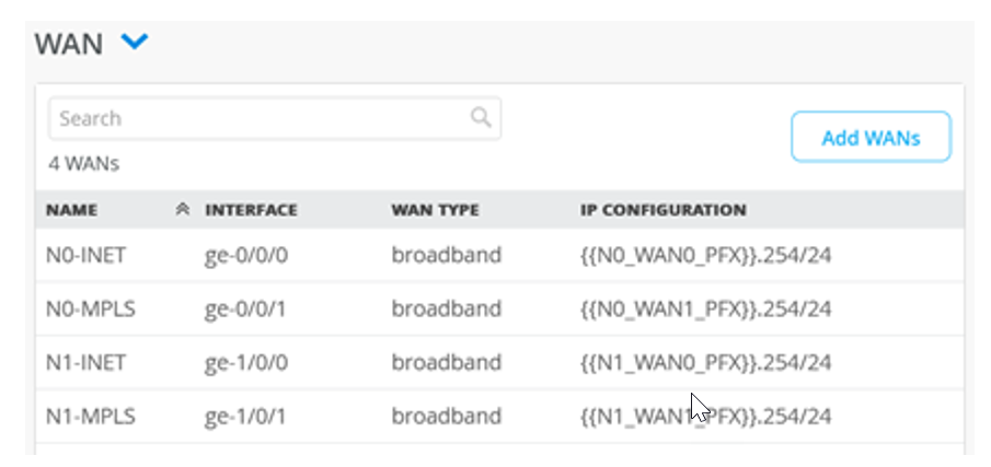
Define the VRRP Interfaces
Next, you’ll define a Network for the redundant LAN interfaces for VRRP and cluster support.
-
In the Juniper Mist cloud portal, click Organization
> WAN > Networks.
Figure 17: Configure Traffic Source
A list of existing networks, if any, appears.
-
Complete the configuration for the LAN interface with the following
details:
- Network: HAHUB-LAN1
- Interfaces: ge-0/0/3,ge-1/0/3
- Redundant: Enabled
- RE Index: 3 (As a convention, we usually use the last octet as an index).
- IP Address: {{HAHUB_LAN1_PFX}}.1
- Prefix: 24 (Remains same)
Figure 18: Redundant LAN Interface Configuration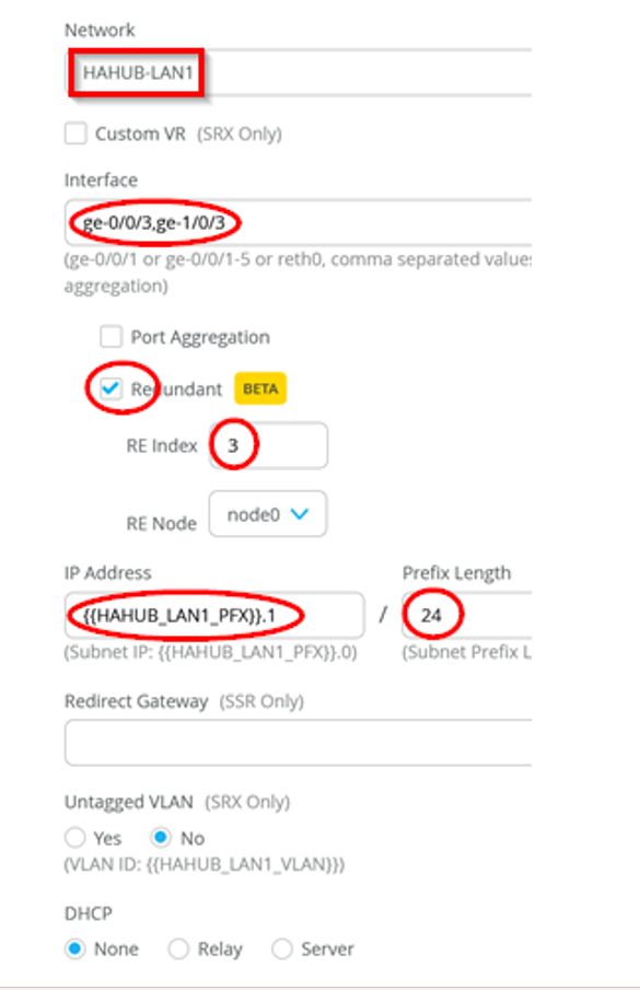
Figure 19 shows details of LAN interfaces configured for hub profile.
Figure 19: LAN Interface Configured for Hub Profile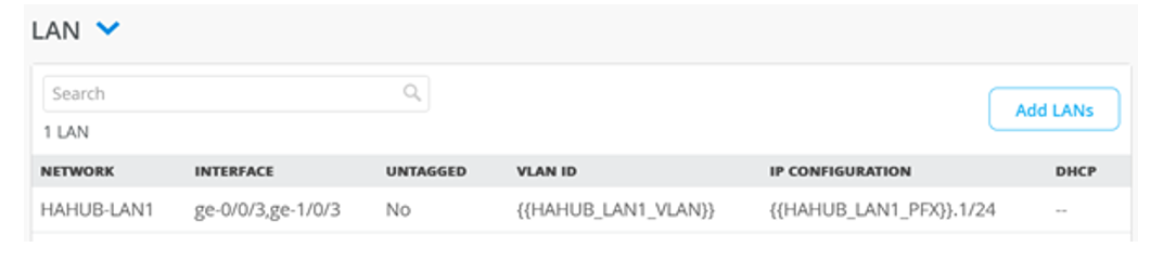
Configure Traffic Steering Profile
Traffic steering rules direct the flow of data traffic from one location or device to another. These rules help control how data packets are routed within a network, ensuring efficient and optimized data delivery. Traffic steering rules can be set up for various purposes, such as load balancing, traffic optimization, security, and quality of service (QoS) management. This is the Mist expression of “how” we send our “who” Networks to our “what” Applications.
For example, in a load balancing scenario, Traffic Steering rules might determine how incoming data traffic is distributed across multiple servers to prevent overload on any single server and ensure even distribution of the workload. In a security context, Traffic Steering rules could be used to direct certain types of traffic through specific security checkpoints or firewalls for inspection before allowing them into the network.
For your Traffic Steering network, keep in mind Session Smart Secure Vector Routing™. Your Session Smart routers are constantly communicating with one another with synchronous and asynchronous Bidirectional Forwarding Detection for liveness and path health for path selection in real-time. Traffic Steering then is an order of what paths you’d like traffic to take.
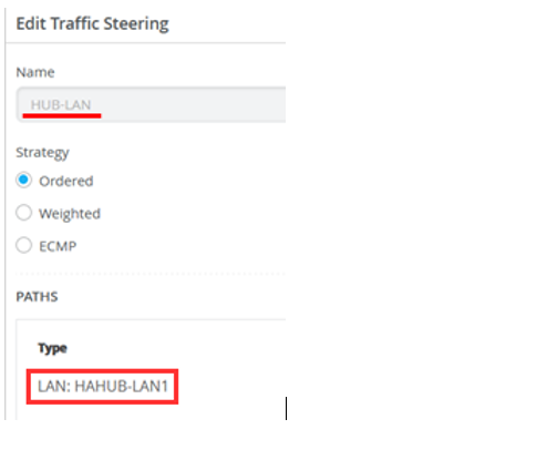
Scroll down to the TRAFFIC STEERING pane and edit the entry to change the rule for HUB-LAN to Paths / Type: LAN: HAHUB-LAN1
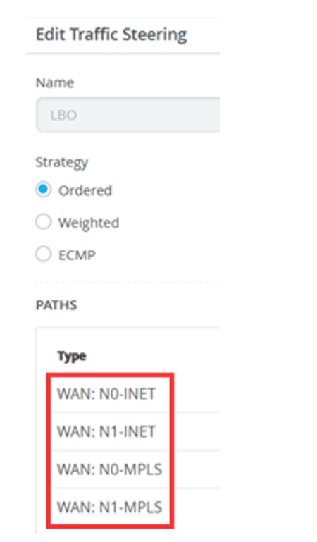
For LBO
- WAN: N0-INET
- WAN: N1-INET
- WAN: N0-MPLS
- WAN: N1-MPLS
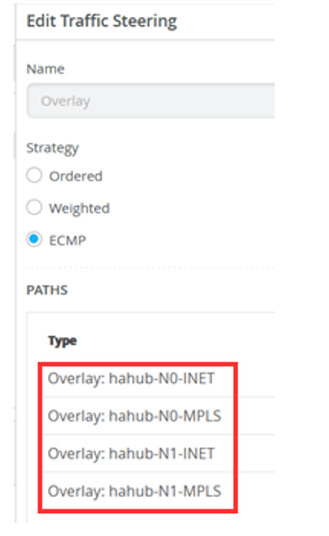
For Overlay
- Overlay: hahub-N0-INET
- Overlay: hahub-N0-MPLS
- Overlay: hahub-N1-INET
- Overlay: hahub-N1-MPLS
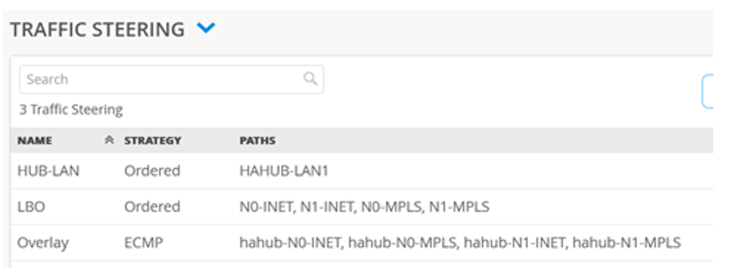
The Traffic steering rules now combine the interfaces of the two nodes as shown in Figure 23.
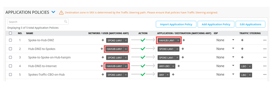
Modify Application Policies
The Application Policies are like the ones for hub1 or hub2. But this time, you’ll change what was HUB1-LAN1 to HAHUB-LAN1. The changes are noted in bold font.
For example, wherever applicable, change HUB1-LAN to HAHUB-LAN1.
| No. | Rule Name | Network | Action | Destination | Steering |
|---|---|---|---|---|---|
| 1 | Spoke-to-Hub-DMZ | SPOKE-LAN1 | Pass | HAHUB-LAN1 | N/A |
| 2 | Hub-DMZ-to-Spokes | HAHUB-LAN1 | Pass | SPOKE-LAN1 | N/A |
| 3 | Spoke-to-Spoke-on-Hub-hairpin | SPOKE-LAN1 | Pass | SPOKE-LAN1 | N/A |
| 4 | Hub-DMZ-to-Internet | HAHUB-LAN1 | Pass | ANY-LBO | LBO |
| 5 | Spokes-Traffic-CBO-on-Hub | SPOKE-LAN1 | Pass | ANY | LBO |
Figure 24 shows the details of the updated application policies after you save your changes.
Create Spoke Templates
-
Create two matching spoke templates. You need spoke template for the device
in standalone mode and another spoke template for devices in high
availability cluster.
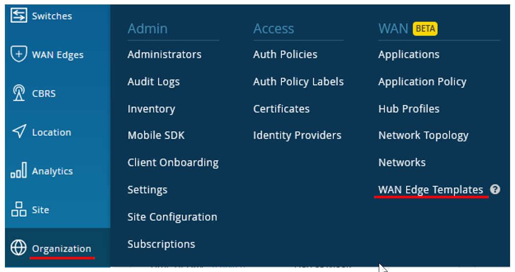
In the Juniper Mist™ portal, click Organization > WAN > WAN Edge Templates. A list of existing templates, if any, appears.
Figure 25: Accessing WAN Edge Templates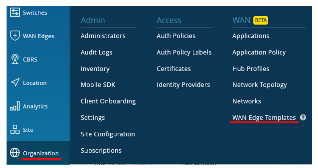
-
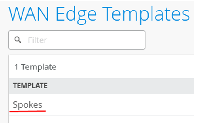
Create the new Spoke Template by cloning the existing template and
modifying the clone. Simply select the existing profile Spokes and select
Clone.
Figure 26: WAN Edge Templates
-
In the upper right corner of the screen, click More and select Clone.
Figure 27: Cloning Existing WAN Edge Template

-
Name the new Hub Profile: haspoke.
Figure 28: Renaming Cloned Template
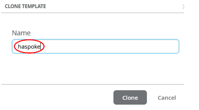
Best practice: Refresh your browser after cloning. This ensures that objects are refreshed.
-
Change your clone Template. Remove all older WAN interfaces and configure
four WAN interfaces according to the details in Table 4.
Table 4: WAN Interfaces Details for Spoke Template Option First WAN Interface Second WAN Interface Third WAN Interface Fourth WAN Interface Name ( indicates which topology it uses) N0-INET N0-MPLS N1-INET N1-MPLS WAN Type Ethernet Ethernet Ethernet Ethernet Interface ge-0/0/0 ge-0/0/1 ge-1/0/0 ge-1/0/1 IP Configuration: DHCP Static - IP Address:{{WAN1_PFX}}.2
- Gateway: {{WAN1_PFX}}.1
- Prefix: 24
DHCP Static - IP Address: {{WAN1_PFX}}.3
- Gateway: {{WAN1_PFX}}.1
- Prefix: 24
Overlay Hub Endpoints - Endpoint1: hahub-N0-INET
- Endpoint2: hahub-N1-INET
- Endpoint1: hahub-N0-MPLS
- Endpoint2: hahub-N1-MPLS
- Endpoint1:hahub-N0-INET
- Endpoint2: hahub-N1-INET
- Endpoint1: hahub-N0-MPLS
- Endpoint2: hahub-N1-MPLS
Figure 29: WAN Interface Configuration for Spoke Template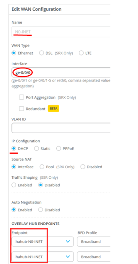 Figure 30: WAN Interface (Second) Configuration for Spoke Template
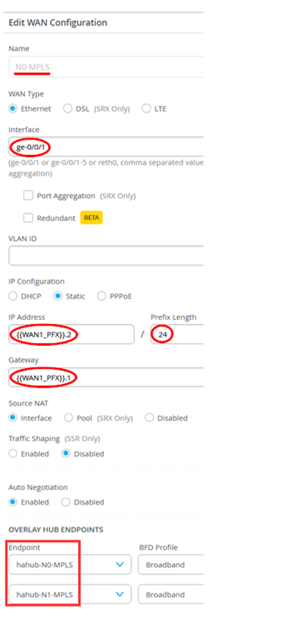 Figure 31: WAN Interface (Third) Configuration for Spoke Template
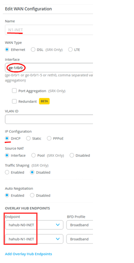 Figure 32: WAN Interface (Fourth) Configuration for Spoke Template
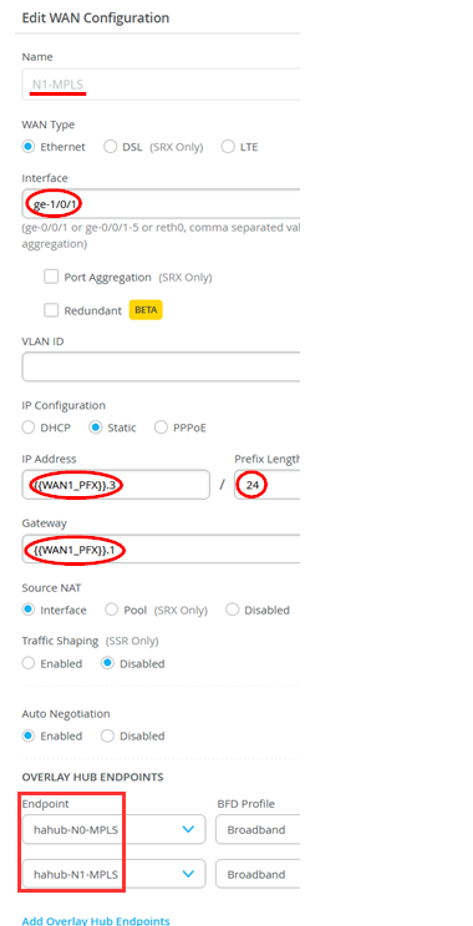
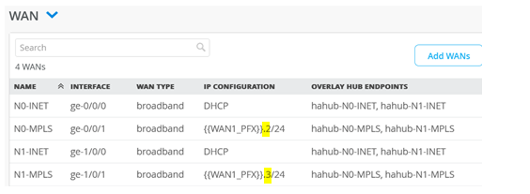
-
Mirror the configuration for each WAN and node1 interface as shown in Figure 33. In this
configuration, the Internet interfaces each get a DHCP-Lease and the MPLS
interfaces have a different static IP address in the same subnet.
Figure 33: WAN Interfaces Configured in Spoke Template
-
Edit the SPOKE-LAN1 interface to define it as a redundant interface for
VRRP.
Edit the LAN (SPOKE-LAN1) interface with the following details:
- Network: SPOKE-LAN1
- Add the interfaces: ge-0/0/3, ge-1/0/3
- Redundant: Enabled
- RE Index: 3 (As per convention, use the last octet as your index)
- IP Address: {{SPOKE_LAN1_PFX}}.1
- Prefix: 24 (did not change)
Figure 34: LAN Interface Configuration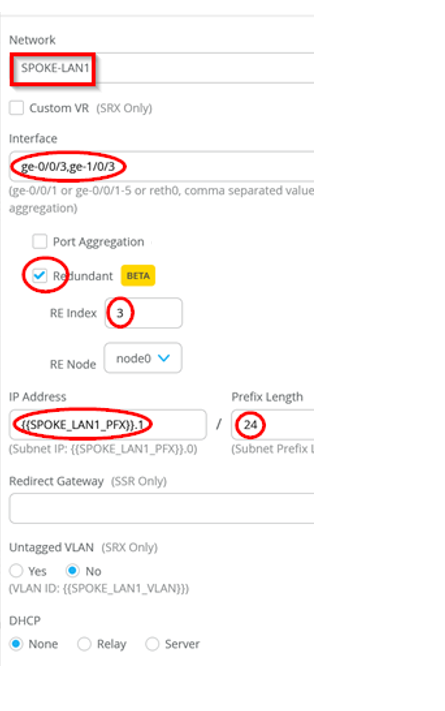
Figure 35 shows the overview the LAN interface you modified.
Figure 35: LAN Interface Configured in Spoke Template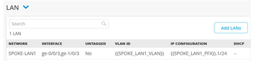
-
Change the traffic steering rules to combine the interfaces of the two HA
nodes. Hence, change the existing rule for the Overlay as
follows:
Paths / Type
- Type=Overlay: hahub-N0-INET
- Type=Overlay: hahub-N0-MPLS
- Type=Overlay: hahub-N1-INET
- Type=Overlay: hahub-N1-MPLS
Figure 36: Modify Traffic Steering Rules in Spokes Template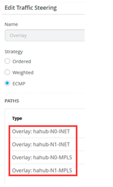 Figure 37shows the modified traffic steering rules.Figure 37: Modified Traffic Steering Rules in Spokes Template
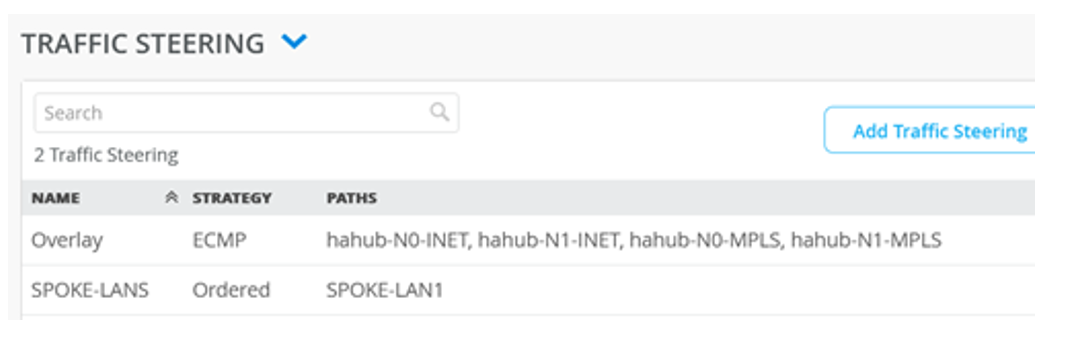
-
The Application Policies are VERY similar to the ones for spokes. We have
indicated the changes you need to make below Bold Font. Modify the
application policies according to the details provided in Table 5.
Table 5: Application Policies in Spoke Template No. Rule Name Network Action Destination Steering 1 Spoke-to-Hub-DMZ SPOKE-LAN1 Pass HAHUB-LAN1 N/A 2 Spoke-to-Spoke-via-Hub SPOKE-LAN1 Pass SPOKE-LAN1 N/A 3 Hub-DMZ-to-Spoke HAHUB-LAN1 Pass SPOKE-LAN1 N/A 4 Internet-via-Hub-CBO SPOKE-LAN1 Pass ANY N/A Figure 38 shows the details of application policy rules.
Figure 38: Modified Application Policies in Spoke Template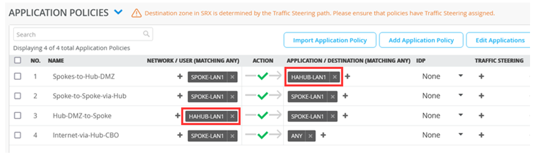
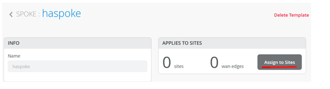
-
Assign the spoke template to site. Scroll to the top of the WAN Edge
Templates page and click Assign to Sites under Spokes
pane.
Figure 39: Assign Spoke Template to Sites
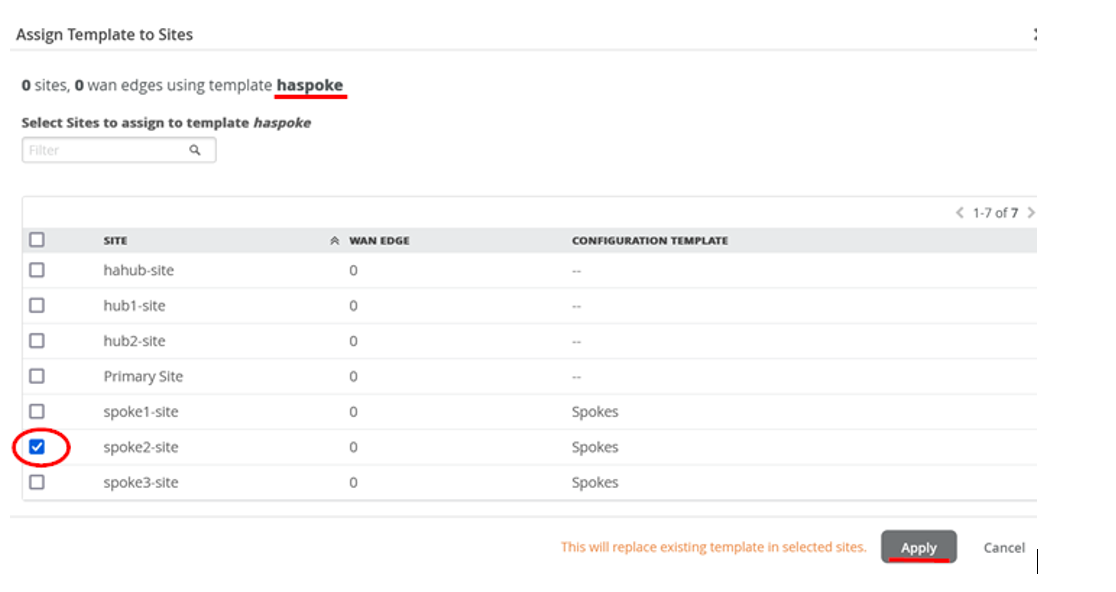
-
In the Assign Template to Sites, check that you are using the
haspoke template and select the site spoke2-site before
you hit Apply.
Figure 40: Selecting Site for Assigning Spoke Template
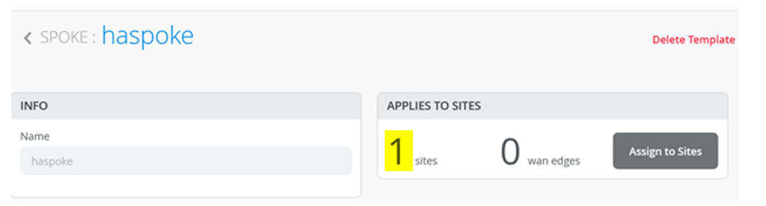
-
Check that your Template has now at least 1 Site assigned.
Figure 41: Spoke Templates Applied to Sites
Create the Second Spoke Template
Now it’s time to clone our WAN Edge Template for our redundant spoke Node.
-
In the Juniper Mist cloud portal, click Organization
> WAN > WAN Edge
Templates. A list of existing templates, if any,
appears.
Figure 42: WAN Edge Template
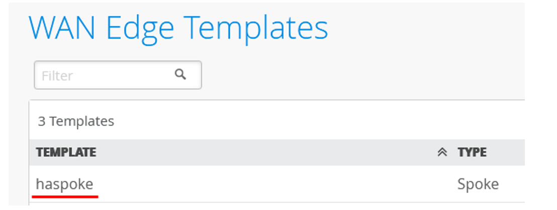
-
Create the new Spoke Template by cloning the existing and modifying
the clone. Click on the existing profile haspoke.
Figure 43: Select WAN Edge Template for Cloning
-
In the upper right corner of the screen, click More
and select Clone.
Figure 44: Cloning WAN Edge Template

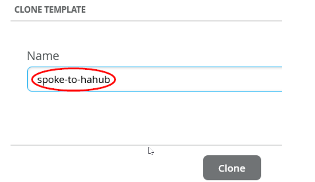
-
Name the new template as spoke-to-hahub and click
Clone.
Figure 45: Renaming Cloned Template
If you see any errors while naming the profile, refresh your browser.
Let’s edit the interfaces for the second node. There are few differences between this template and the former template. You have one single node with only two WAN interfaces. Configure the WAN interfaces:
- Delete the existing WAN interface Name: N1-INET
- Delete the existing WAN interface Name: N1-MPLS
Figure 46 shows the result.
Figure 46: WAN Interface Details in New Cloned Template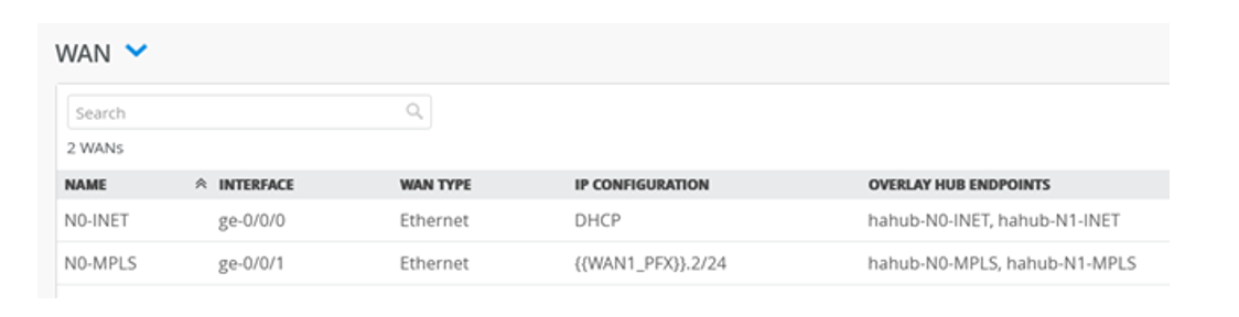
-
The LAN interfaces are no longer redundant. To archive this, configure the
following Configure according to Figure 47.
Figure 47: LAN Interface Configuration
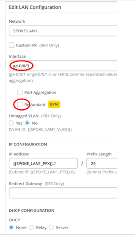
Configure the following options:
- Change the Interface: ge-0/0/3
- Change Redundant: Disabled
Figure 48 shows the result.
Figure 48: LAN Interface Details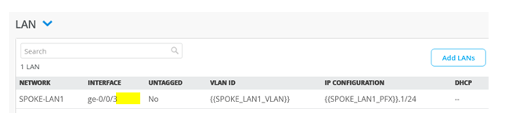
-
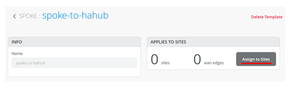
Assign the spoke template to site. Scroll to the top of the WAN Edge
Templates page and click Assign to Sites under Spokes
pane
Figure 49: Assign Template to Site
-
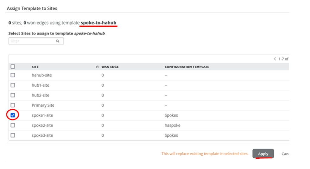
In the Assign Template to Sites, ensure that you are using the
spoke-to-hahub template and select the site
spoke1-site
Figure 50: Selecting Site for Assigning Template
-
Ensure that your template is now assigned to a site. Check that your
Template now has at least 1 Site assigned as shown in
Figure 51.
Figure 51: Spoke Templates Applied to Sites
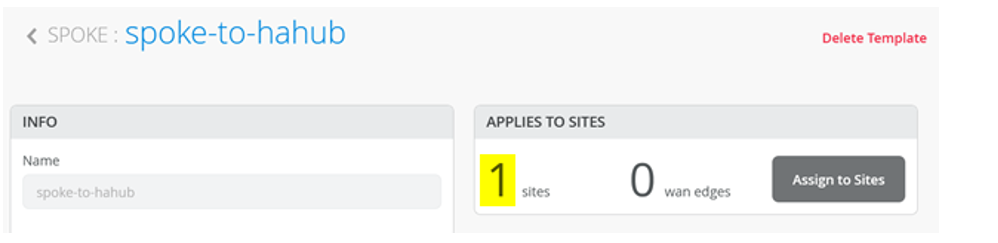
Figure 52 shows the list of configured spoke templates.
Figure 52: List of WAN Edge Templates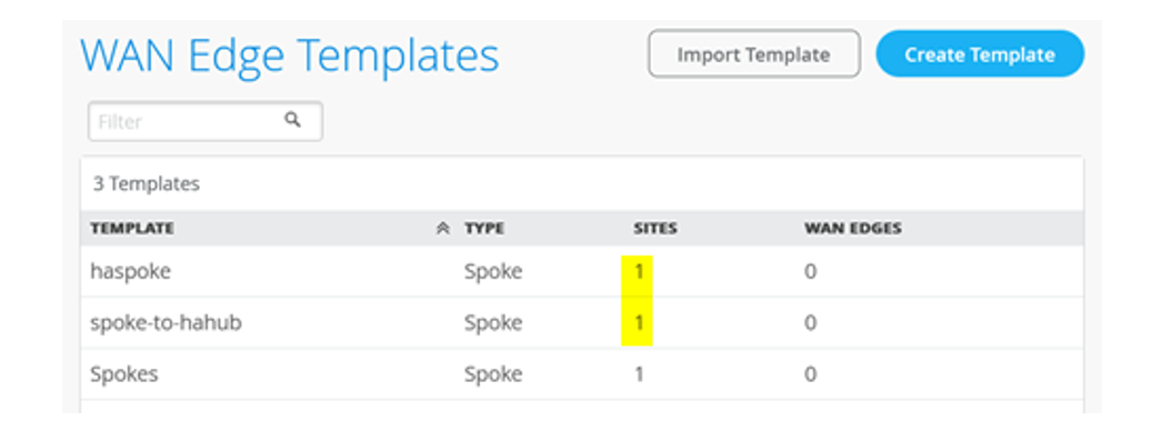
Onboard your Devices
You can Claim or Adopt to onboard devices into your organization inventory. For details on getting your Session Smart Router up and running in the Mist cloud, see SSR Series Devices.
-
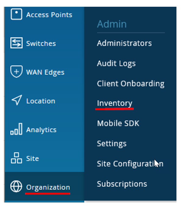
In the Juniper Mist portal. click Organization >
Admin >Inventory.
Figure 53: Navigating to Inventory
-
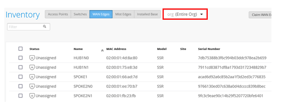
Refresh your browser and check under WAN Edges to find out if your Session
Smart Router is part of the inventory. Ensure you set the view as
org (Entire Org) as shown in Figure 54.
Figure 54: Session Smart Router in Inventory
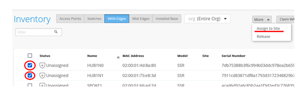
-
Select the two devices/nodes together for the HA hub and click
Assign to Site.
Figure 55: Assigning Session Smart Routers (HA Pair) to Site
-
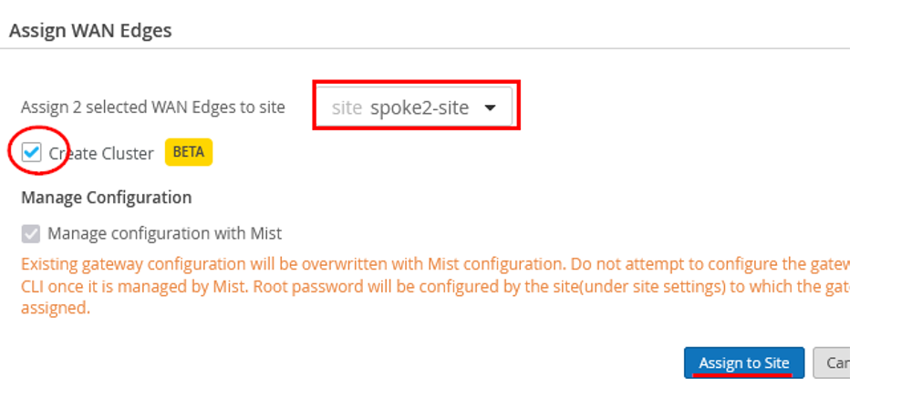
In Assign WAN Edges page, select hahub-site and
enable the Create Cluster option.
Figure 56: Assign Spoke Devices to Site and Initiate Cluster Formation
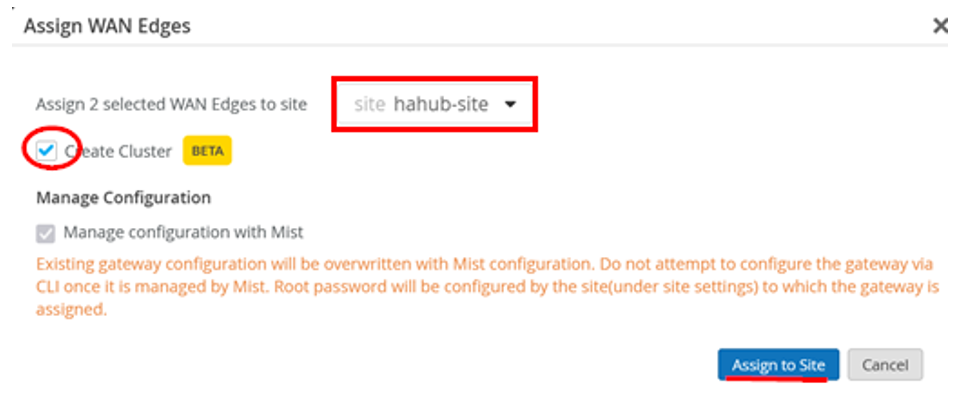
-
Click Assign to Site.
The portal displays the details of WAN edge devices assigned to site and progress of cluster formation. You can close this dialog box.
Figure 57: HA Cluster Formation for Assigned Devices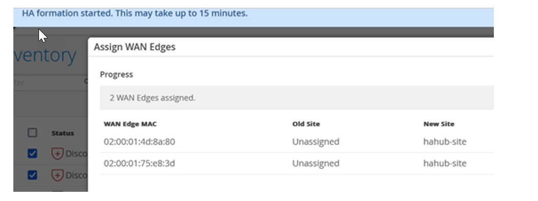
-
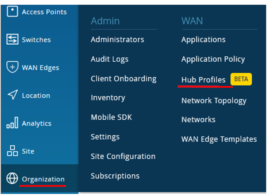
In the Juniper Mist portal, click Organization
> WAN > Hub
Profiles. The Hub Profile displays the list of existing
profiles.
Figure 58: Navigating to Hub Profiles
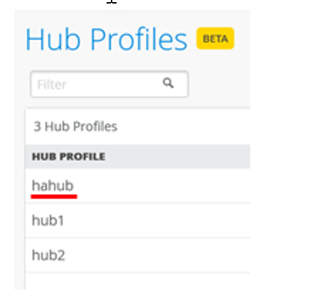
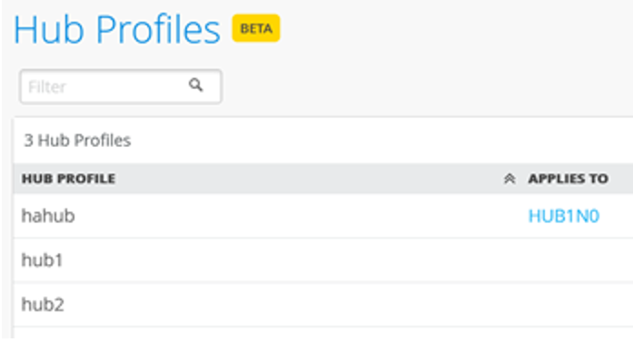
-
Click the hub profile (hahub) that you want to assign to a site.
Figure 59: Select Hub Profile
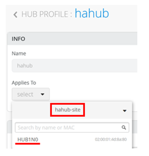
-
Under the Applies To option, select the site
(hahub-site) from the list of available sites.
Figure 60: Select Sites for Applying Hub Profile
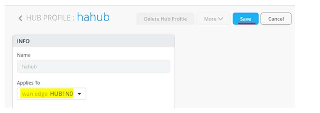
-
Check if have correct WAN Edge device selected, and click
Save.
Figure 61: Select WAN Edge Device to Apply Template
-
You should now see the HA devices assigned to their Hub Profile in
the as shown in Figure 62.
Figure 62: Hub Profile Assignment Summary
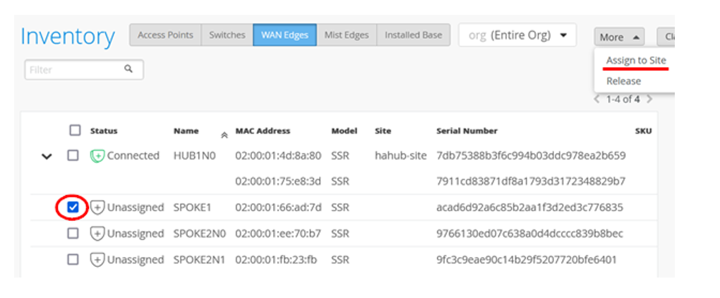
-
Select the spoke device (SPOKE1) and click Assign to
Site.
Figure 63: Assign Spoke Device To Site
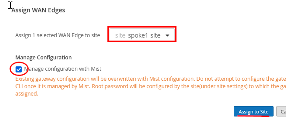
-
In Assign WAN Edges page, select spoke1-site and enable Manage
configuration with Mist.
Figure 64: Assign WAN Edge Device to Site
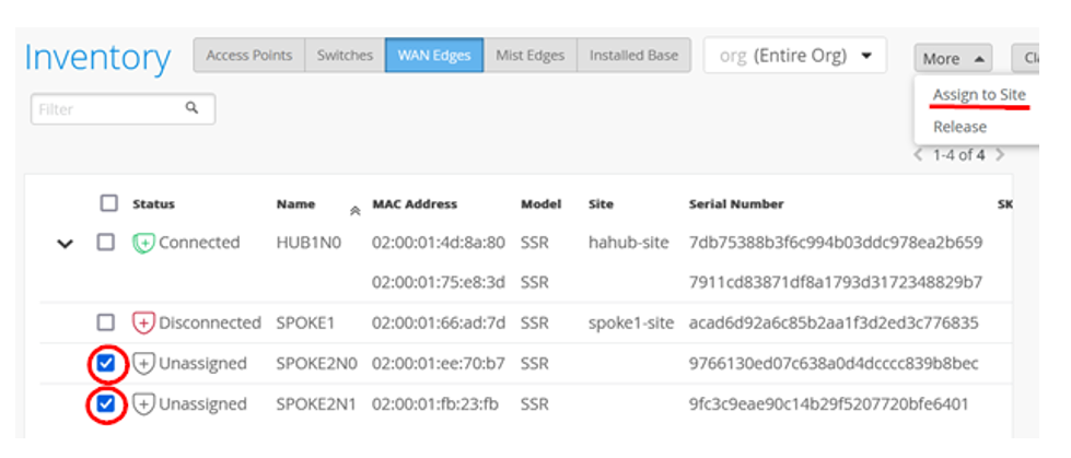
-
Select the two spoke devices that will form cluster (Spoke-Cluster) and
click Assign to Site.
Figure 65: Assign Spoke Devices to Site
-
In the Assign WAN Edges, select spoke2-site and enable Create
Cluster .
Figure 66: Assign two Spoke Devices to Site and Initiate Cluster Formation
The portal displays the details of WAN edge devices assigned to site and progress of cluster formation as shown in Figure 67.
Figure 67: Cluster Formation Progress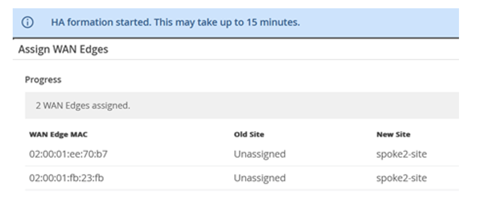
-
Go to Inventory Page. Figure 68 shows the details of devices assigned to site and high
availability pairs.
Figure 68: Inventory Display of HA Pair Details
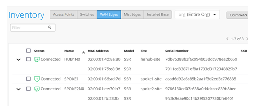
Refresh your browser and check under WAN Edges to find out if your Session Smart Routers are part of the inventory as HA Pairs.
Now you have a topology with highly available hub and spoke Juniper® Networks Session Smart™ Routers using the WAN Assurance solution.
Replace an Session Smart Router Node in a High Availability Cluster
You can replace an Session Smart Router device from a high availability cluster setup with few simple steps.
Before you replace a Session Smart Router node from the cluster, you must:
- Remove the cluster fabric cables from the node being replaced and connect it to the new replacement node.
- Make sure that the replacement Session Smart Router is both the same model as the device being replaced and has a firmware version higher than 6.0
- If you are replacing a node with a new out-of-the box Session Smart Router,
ensure that you:
- Claim the new Session Smart Router to the same site where the Session Smart Router cluster is present.
- Upgrade the firmware of the Session Smart Router to a version above 6.0.
-
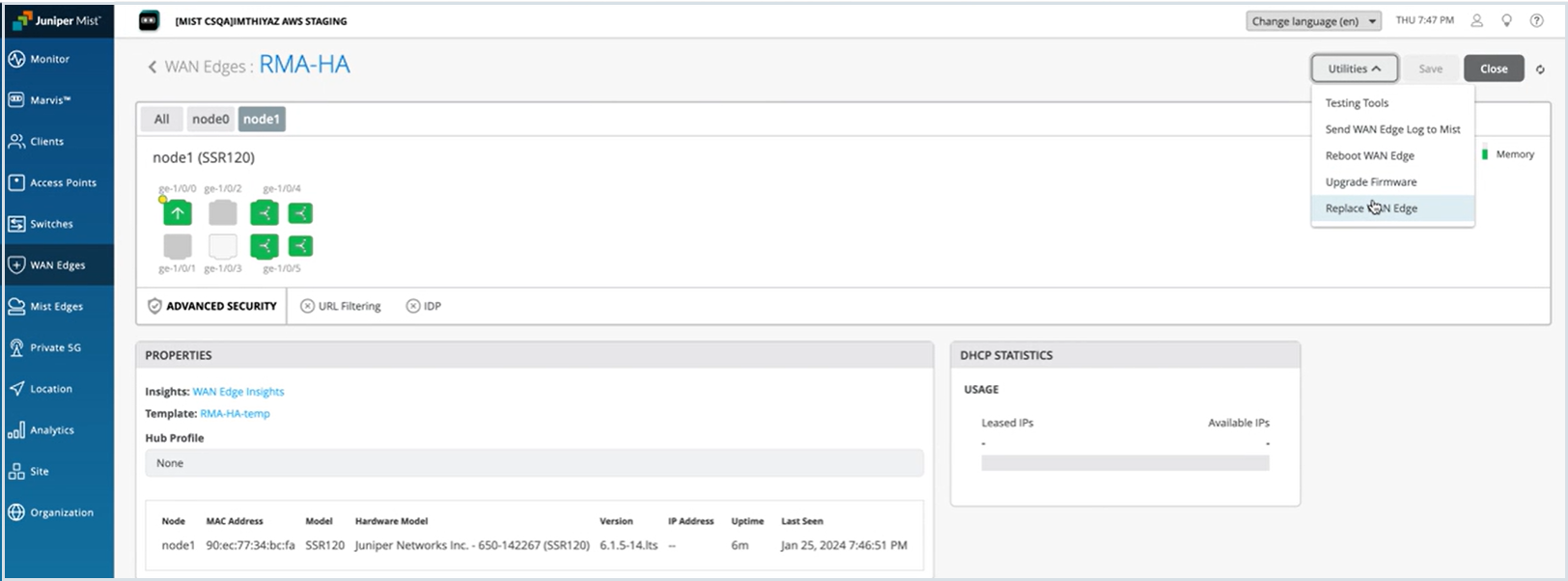
Select Replace WAN Edge from Utilities drop-down.
Figure 69: Select Session Smart Routers (HA Pair) to Replace
-
On the Replace WAN Edge window, select the old Session Smart Router node
that you want to replace and select the new replacement device’s MAC address
from the MAC Address of available WAN Edge drop-down
list.
Figure 70: Replace Session Smart Router with Another Device
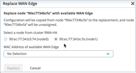
After you click Replace, allow about 15 minutes to complete the replacement procedure.
Refresh your browser and check under WAN Edges to find out if your Session Smart Routers high availability setup is updated and available as a part of the inventory.
Replace a Standalone Session Smart Router
You can replace connected or disconnected Session Smart Router with another device of the same model.
-
On the Replace WAN Edge window, select the new replacement device’s MAC
address from the MAC Address of unassigned WAN Edge
drop-down list.
Figure 71: Replace a Standalone SRX Series Firewall

Juniper Mist portal displays a list of supported models available in the inventory page in unassigned state.
After you click Replace, allow about 15 minutes to complete the replacement procedure. System copies the configuration of the replaced Session Smart Router into the new device. The replaced Session Smart Router continues to be part of the site in unassigned state.
Refresh your browser and check under WAN Edges to find out if your Session Smart Router is available as a part of the inventory.
Delete a High Availability Cluster
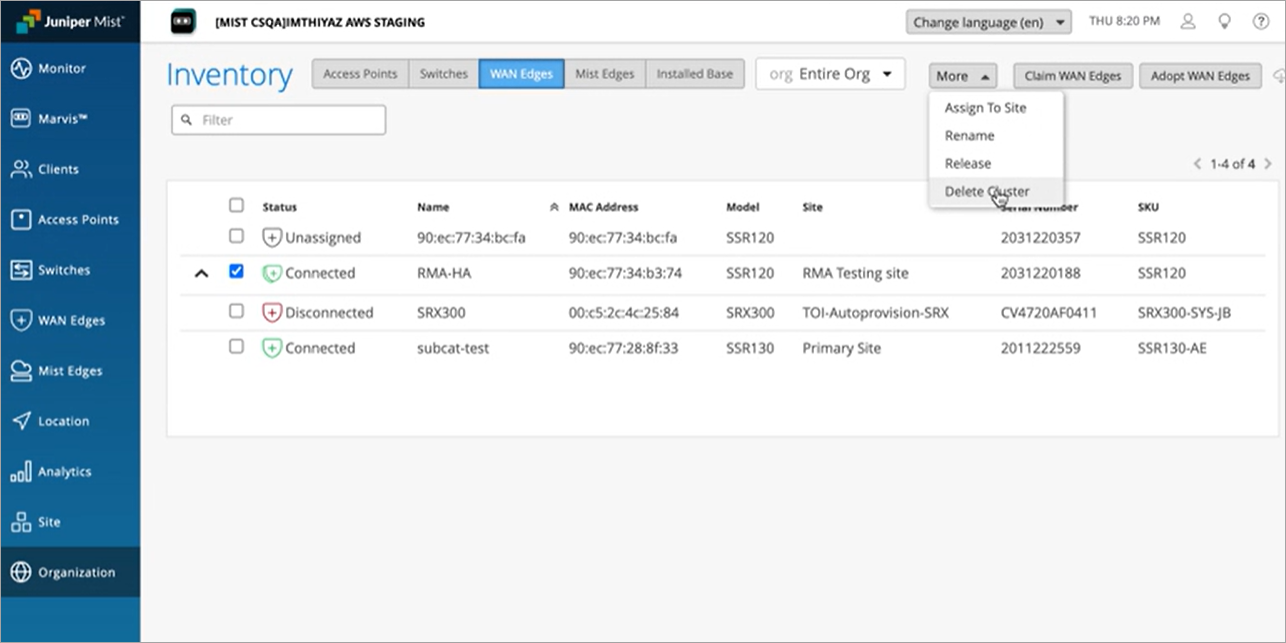
-
Select the high availability pair and click Delete
Cluster under More.
Figure 72: Select Session Smart Routers (HA Pair) to Delete
Click Confirm on the Confirm Delete Cluster message.
Figure 73: Delete Session Smart Router with Another Device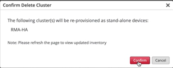
Juniper Mist re-provisions the devices as standalone devices in the same site.
Refresh your browser and check under WAN Edges to find out if your Session Smart Routers are available as standalone devices in the inventory.