- play_arrow Overview
- play_arrow Platform Considerations
- play_arrow WAN Configuration for SRX Series Firewalls
- WAN Assurance Configuration Overview
- Configure Sites and Variables for SRX Series Firewalls
- Configure Applications for SRX Series Firewalls
- Configure Networks for SRX Series Firewalls
- Configure Application Policies on SRX Series Firewalls
- Configure Hub Profiles for SRX Series Firewalls
- Configure WAN Edge Templates for SRX Series Firewalls
- Routing Configuration on SRX Series Firewalls
- Onboard SRX Series Firewalls for WAN Configuration
- IDP-Based Threat Detection for SRX Series Firewalls
- Enable Application Visibility on SRX Series Firewalls
- Monitor the Service Status of SRX Series Firewalls
- Upgrade a WAN Edge SRX Series Firewalls
- Configure a Custom VR for SRX Series Firewalls
- Revoke DHCP Lease on a WAN Edge Device
- Reserve DHCP IP Address
- play_arrow WAN Assurance Design
- play_arrow Secure Edge Connector
- play_arrow Cellular Edges
- play_arrow Monitor and Troubleshoot
- WAN Assurance Monitoring, SLE, and Troubleshooting Overview
- Monitor SRX Series Firewall Deployed as WAN Edge
- Monitor Session Smart Router Deployed as WAN Edge
- Service-Level Experiences for Session Smart Router Deployed as WAN Edge
- Troubleshoot Session Smart Router Deployed as WAN Edge
- Speed Tests for Session Smart Router Deployed as a WAN Edge (BETA)
- Dynamic and Manual Packet Captures
- Troubleshoot SRX Series Firewalls
- Replace a WAN Edge Device
- WAN Edge Testing Tools
Configure Hub Profile for Session Smart Routers
Each hub device in a Juniper Mist™ cloud topology must have its own profile. Hub profiles are a convenient way to create an overlay and assign a path for each WAN link on that overlay in Juniper WAN Assurance.
The difference between a hub profile and a WAN edge template is that you apply the hub profile to an individual device that’s at a hub site. And the WAN edge templates are bound to spoke sites that have multiple devices and bound with the same template across multiple sites. Every Hub WAN interface creates an overlay endpoint for spokes. Spoke WAN interfaces map the appropriate Hub WAN interfaces, defining the topology. Hub profiles drive the addition, removal of paths on your overlay.
When you create a hub profile for the Juniper® Session Smart™ Routers, the Mist cloud generates and installs the SSL certificates automatically. It also sets up WAN uplink probes for failover detection.
In this task, you create a hub profile and then clone the same profile to create a second hub profile in the Juniper Mist cloud portal.
Configure a Hub Profile
A hub profile comprises the set of attributes that associate with a particular hub device. Hub profiles include name, LAN,WAN, traffic steering, application policies, and routing options. You can assign the hub profile to a hub device and after a hub profile is loaded onto the site, the device assigned to the site picks up the attributes of that hub profile.
To configure a hub profile:
Add WAN Interfaces to the Hub Profile
Create WAN interfaces for the hub profile. WAN interfaces become the connection across the SD-WAN. The hub profile automatically creates an overlay endpoints for each WAN interface. Note that the overlay Hub Endpoints is where you tell the spoke (branch) about the hub endpoints.
To add WAN interfaces to the hub profile:
Hub-to-spoke Traffic Steering
The hub profiles let you control t
- Click Save.
Figure 1 shows the list of WAN interfaces you created.
shows the list of WAN interfaces you created.
Figure 1: Configured WAN Interfaces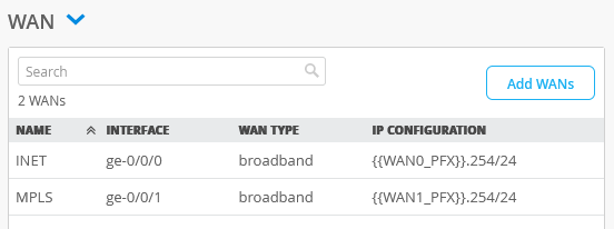
Configure LAN in the Hub Profile
Hub-side of LAN interfaces connect a hub device to the LAN segment.
In the LAN section of the hub profile page, you can configure the settings such as IP Address, DHCP, Custom VR, and LAN interface. The LAN configuration settings in the hub profile are the same as those in the WAN Edge template. The steps listed in Configure LAN apply to configuring LAN in the hub profile as well.
For LAN interface sample configuration values, refer to Table 3.
| Fields | LAN Interface |
|---|---|
| Network | HUB1-LAN1 (existing network selected from drop-down list) |
| Interface | ge-0/0/4 |
| IP Address | {{HUB1_LAN1_PFX}}.1 |
| Prefix Length | 24 |
| Untagged VLAN | No |
| DHCP | No |
Configure Traffic-Steering Policies
Traffic steering is where you define the different paths that application traffic can take to traverse the network. The paths that you configure within traffic steering determine the destination zone. For any traffic steering policy, you need to define the paths for traffic to traverse and strategies for utilizing those paths. Strategies include:
- Ordered—Starts with a specified path and failover to backup path(s) when needed
- Weighted—Selects the paths with lowest cost and in case of equal cost paths load balances traffic
- Equal-cost multipath—Load balances traffic equally across multiple paths
When you apply a hub profile to a device, the traffic-steering policy determines the overlay, WAN and LAN interfaces, order of policies, and usage of Equal Cost Multi-Path (ECMP). The policy also determines how interfaces or a combination of interfaces interact to steer the traffic.
To configure traffic-steering policies:
- Configure three traffic-steering policies: one for the overlay, one for the
underlay, and one for the central breakout, according to the details
provided in Table 4 .
Table 4: Traffic-Steering Policy Configuration Fields Traffic Steering Policy 1 Traffic Steering Policy 2 Traffic Steering Policy 3 Name HUB-LAN Overlay Central Breakout Strategy Ordered ECMP Ordered PATHS For path types, LAN and WAN networks created already are made available for selection as endpoints. Type—LAN
Network—HUB1-LAN1
Type—WAN
Network —hub1-INET and hub1-MPLS
Type—WAN
Network—WAN: INET and WAN: MPLS
Note:Order of application policies do not have any effect on Session Smart Router configuration. As good practice, we recommend you to place global rules towards the end of the policy rules list.
Associating traffic steering policy on each application rule is not a requirement for Session Smart Router. When you use Session Smart Routers, the system announces all the routes on each LAN interface using the iBGP-based route distribution.
For the Session Smart Router deployments, for the traffic to traverse between a hub and spoke, you must use the same name for networks on both sides. The network name for Session Smart Router is identical to a security tenant used for traffic isolation. So, the name must match on both the sides.
Figure 2 shows the list of the traffic-steering policies that you created.
Figure 2: Traffic Steering Policies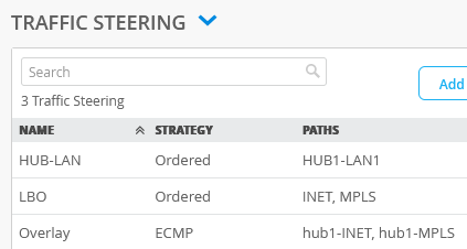
Configure an Application Policy
Application policies are where you define which network and users can access which applications, and according to which traffic-steering policy. The settings in Networks/Users determine the source zone. The Applications and Traffic Steering path settings determine the destination zone. Additionally, you can assign a policy action— permit or deny to allow or block traffic. Mist evaluates and applies application policies in the order in which you list them in the portal. You can use Up arrow and Down arrow to change the order of policies.
Figure 3 shows different traffic-direction requirements in this task (third spoke device and second hub device are not shown in the image).
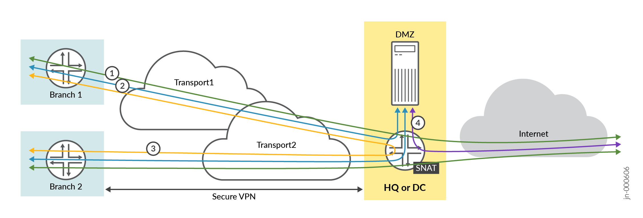
In this task, you create the following application rules to allow traffic:
Rule 1—Allows traffic from spoke sites to reach the hub (and to a server in the DMZ attached to the hub device).
Rule 2—Allows traffic from servers in the DMZ attached to the hub to reach spoke devices.
Rule 3—Allows traffic from spoke devices to reach spoke device hair-pinning through a hub device
Rule 4—Allows Internet-bound traffic from the hub device to the Internet (local breakout). In this rule, define the destination as "Any" with IP address 0.0.0.0/0. The traffic uses the WAN underlay interface with SNAT applied to reach IP addresses on the Internet as a local breakout.
Note:Avoid creating rules with same destination name and IP address 0.0.0.0/0. If required, create destinations with different names using IP address 0.0.0.0/0.
From the spoke devices to the Internet directly (not passing through the hub device). In this rule, define the destination as "Any" with IP address 0.0.0.0/0. The traffic uses the WAN underlay interface with SNAT applied to reach IP addresses on the Internet as a local breakout. This method implements a central breakout at the hub for all spoke devices.
To configure an application policy:
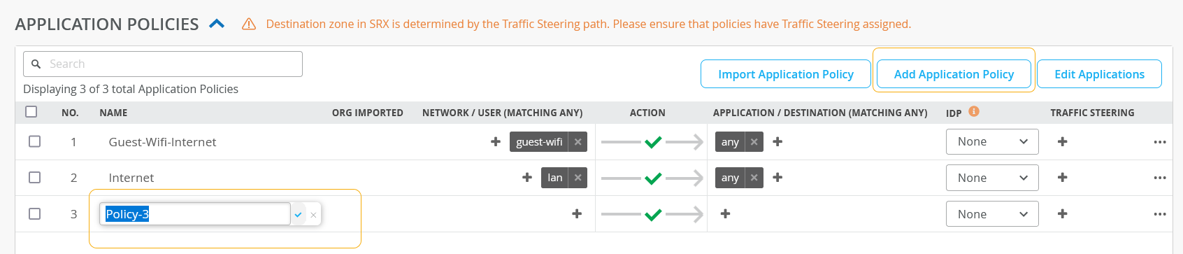
- Click the Name column and give the policy a name,
and then click the blue checkmark to apply your changes. Figure 4: Adding a New Application Policy
- Create application rules according to the details provided in Table 5.
Table 5: Application Policy Rule Configuration S.No. Rule Name Network Action Destination Steering 1 Spoke-to-Hub-DMZ SPOKE-LAN1 Pass HUB1-LAN1 NA 2 Hub-DMZ-to-Spokes HUB1-LAN1 Pass SPOKE-LAN1 NA 3 Spoke-to-Spoke-on-Hub-Hairpin SPOKE-LAN1 Pass SPOKE-LAN1 NA 4 Hub-DMZ-to-Internet HUB1-LAN1 Pass ANY-LBO LBO 5 Spokes-Traffic-CBO-on-Hub ALL.SPOKE-LAN1 Pass ANY LBO Note:If you are configuring application policies for Session Smart Router, associating a traffic steering for each application policy is not a requirement. Table 5 shows application policies configured without any traffic steering profiles. The reason is - when you use Session Smart Router, the system acts as a routing device and announces all routes on each LAN interface. The system automatically applies traffic steering using iBGP-based route distribution when you build the hub and spoke VPN.
Figure 5 shows a list of the application policies that you created.
Figure 5: Application Policies Summary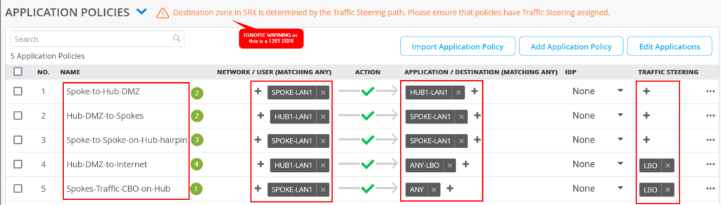
In the above illustration, the green counter marks indicates the policies you have created for the traffic requirements in Figure 3.
Create a Second Hub by Cloning the Existing Hub Profile
Hubs devices are unique throughout your network. You have to create individual profile for each hub device. Juniper Mist provides you an option to create a hub profile by cloning the existing profile and applying modifications wherever required.
To create a second hub profile by cloning an existing hub profile:
- In the upper right corner of the screen, click More
and select Clone. Figure 6: Creating a New Hub Profile By using Clone Option

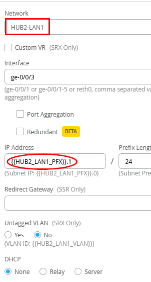
- Start configuring the profile. Since you've used variables when creating
the original hub profile, you don't need to configure all options from the
beginning. You need to change only the required configurations to reflect
HUB2 details. For example, change Network to
HUB2-LAN1 and change IP Address to
{{HUB2_LAN1_PFX}}.1. Figure 7: Edit a Cloned Profile
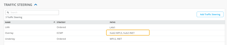
- Confirm that the variables in the configuration have changed to reflect
hub2 profile details. Example: Overlay definitions have changed to hub2-INET
and hub2-MPLS. Figure 8: Updated Traffic Steering Policy
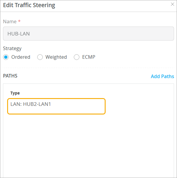
- Scroll down to the TRAFFIC STEERING pane and edit the entry to change the
Paths to LAN: HUB2-LAN1. Figure 9: Update Paths in a Traffic-Steering Policy
- Update the application rules according to the details provided in Table 6. For
example, wherever applicable, change HUB1-LAN to HUB2-LAN.
Table 6: Application Rules Configuration S.No. Rule Name Network Action Destination Steering 1 Spoke-to-Hub-DMZ SPOKE-LAN1 Pass HUB2-LAN1 N/A 1 Hub-DMZ-to-Spokes HUB2-LAN1 Pass SPOKE-LAN1 N/A 3 Spoke-to-Spoke-on-Hub-Hairpin SPOKE-LAN1 Pass SPOKE-LAN1 N/A 4 Hub-DMZ-to-Internet HUB2-LAN1 Pass ANY-LBO LBO 5 Spokes-Traffic-CBO-on-Hub SPOKE-LAN1 Pass ANY LBO Figure 10 shows the details of the updated application policies after you save your changes.Figure 10: Updated Application Policy Summary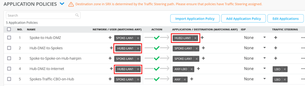
Hub-to-Hub Overlay
The Hub-to-hub overlay feature allows a you to form a peer path between two hub devices. You can utilize the hub-to-hub overlay path as a preferred route for data center traffic originating from sites. Additionally, these hub-to-hub overlays can serve as failover paths in scenarios involving hub-to-spoke connections.
Configure Hub-to-Hub Overlay
To create Hub-to-Hub overlay, the WAN interfaces of one hub map to the WAN interfaces of another hub, thus forming an overlay and designating a traffic pathway.
Hub-to-Hub overlay can utilize different WAN interfaces on both hub devices. It is not mandatory for the overlay to form between identical WAN interfaces on the two hubs.
Consider you have two hubs, Hub device A and Hub device B, and you wish to establish an overlay between them.
Hub device A is equipped with two WAN interfaces: WAN-1-A and WAN-2-A. You must pair these WAN interfaces with the WAN interfaces of Hub device B, which are WAN-1-B and WAN-2-B, marking them as hub endpoints.
Similarly, for Hub device B:
It features two WAN Interfaces: WAN-1-B and WAN-2-B. These should be linked to the WAN Interfaces of Hub Device A (WAN-1-A and WAN-2-A) to complete the setup as hub endpoints.
Use the following steps to create hub endpoints:
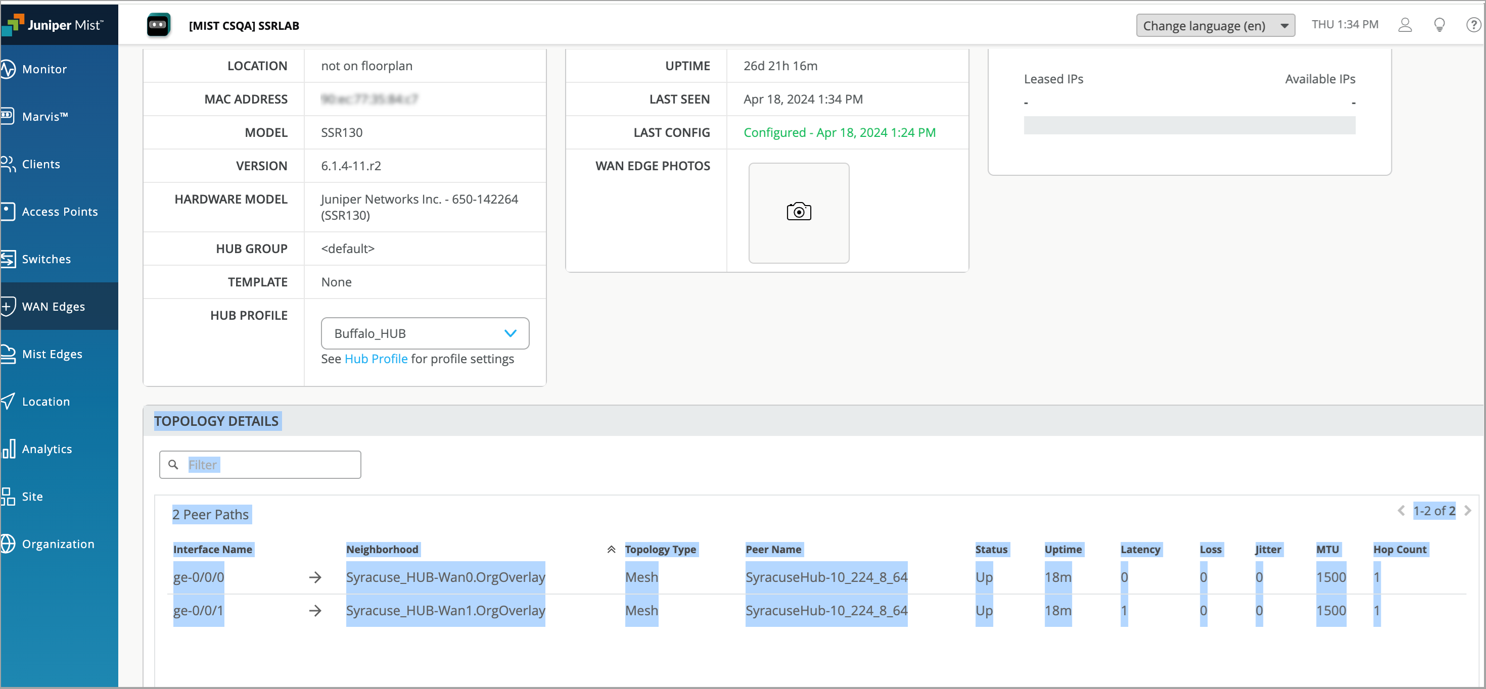
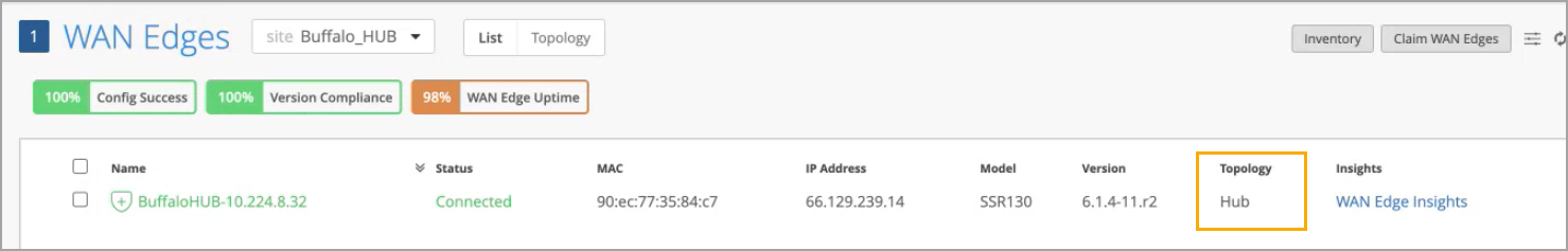
- On Juniper Mist portal, select WAN Edges and click
the hub device. Ensure that the hub device you select must be part of hub
topology. Figure 11: Hub Device in Hub Topology
- On the WAN Edge > Device-Name page, go to Properties section and scroll down to Hub Profile.
- Click the hub profile link to open the Hub Profile page.
- Scroll-down to WAN section and click a WAN interface which you want to use for overlay.
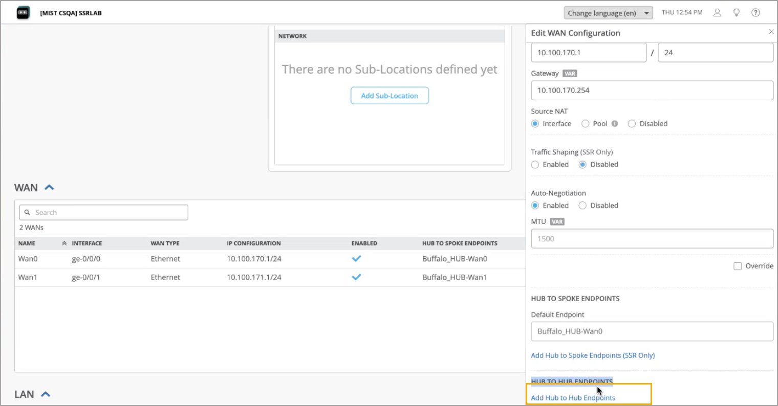
- In the Edit WAN Configuration window, scroll down to
Hub-to-Hub Endpoints and click Add
Hub-to-Hub Endpoints option. Figure 12: Adding Hub-to-Hub Endpoints
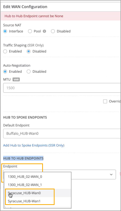
- Select a hub endpoint point (WAN interface) from the drop-down menu.
Choose the WAN interface of the other hub device to establish an
overlay connection. Figure 13: Select WAN Interface for Overlay
- Click Save. The selected hub endpoint appears under Hub to Hub Endpoints columns in WAN pane.
- Select a hub endpoint point (WAN interface) from the drop-down menu.
Choose the WAN interface of the other hub device to establish an
overlay connection.
- Select another WAN interface and repeat the same procedure to add another endpoint.
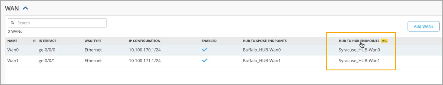
- Now, both endpoints appear under Hub to Hub Endpoints
columns in WAN pane. Figure 14: Configured Hub to Hub Endpoints of First Hub Device
- Click Save.
Now, lets configure WAN interfaces of other hub device to complete the setup as hub endpoints.
- On Juniper Mist portal, select WAN Edges and click the hub device. This is the hub device from which you earlier chose the WAN interface for establishing the overlay.
- On the WAN Edge > Device-Name page, go to Properties section and scroll down to Hub Profile.
- Click the hub profile link to open the Hub Profile page.
- Scroll-down to WAN section and click a WAN interface which you want to use for overlay.
- In the Edit WAN Configuration window, scroll down to Hub-to-Hub Endpoints and click Add Hub-to-Hub Endpoints option.
- Select a hub endpoint point from the drop-down menu. Select the WAN interface of the same hub device that was configured in the prior procedure
- Click Save. The selected hub endpoint appears under Hub to Hub Endpoints columns in WAN pane.
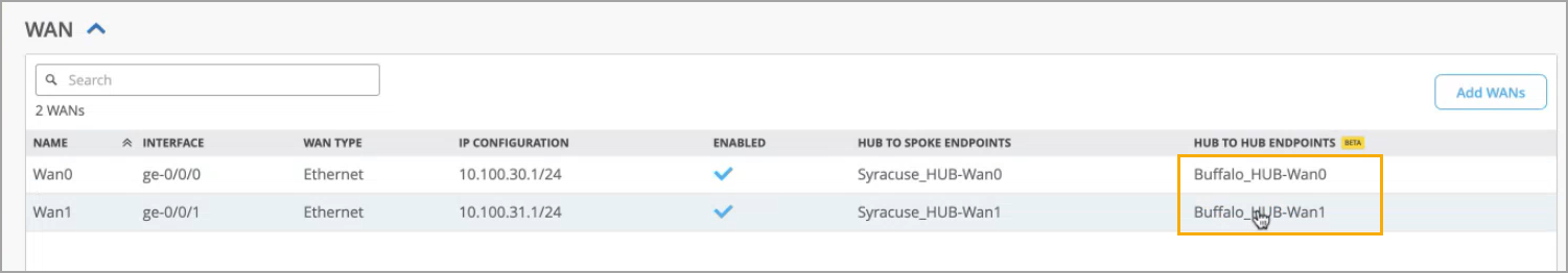
- Select another WAN interface and repeat the same procedure to add another endpoint.
- Now, both endpoints appear under Hub yo Hub Endpoints columns in WAN pane.
Figure 15: Configured Hub to Hub Endpoints of Second Hub Device
- Click Save.
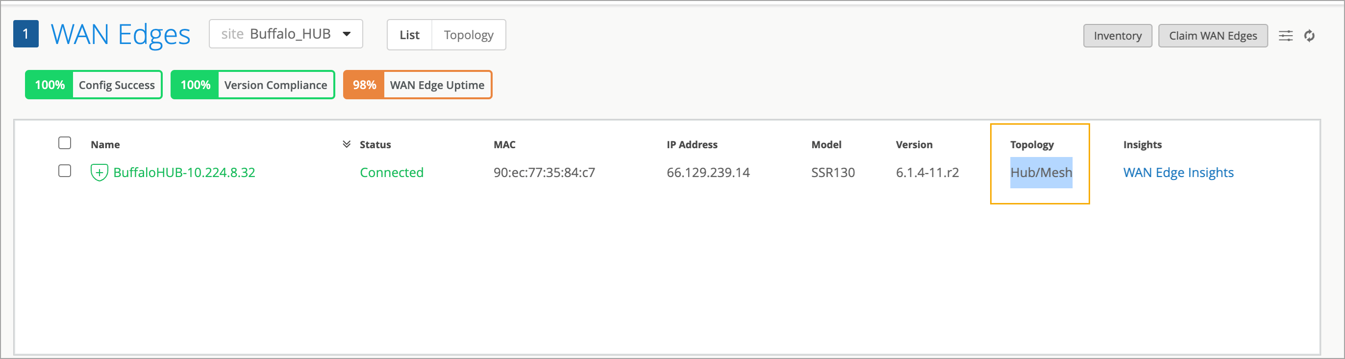
Verification
On Juniper Mist portal, you can verify the established hub-to-hub overlays by checking the topology of the WAN Edge device:
On the WAN Edge page, the Topology column displays Hub/Mesh.