


- play_arrow Overview
- play_arrow Platform Considerations
- play_arrow WAN Configuration for SRX Series Firewalls
- WAN Assurance Configuration Overview
- Configure Sites and Variables for SRX Series Firewalls
- Configure Applications for SRX Series Firewalls
- Configure Networks for SRX Series Firewalls
- Configure Application Policies on SRX Series Firewalls
- Configure Hub Profiles for SRX Series Firewalls
- Configure WAN Edge Templates for SRX Series Firewalls
- Routing Configuration on SRX Series Firewalls
- Onboard SRX Series Firewalls for WAN Configuration
- IDP-Based Threat Detection for SRX Series Firewalls
- Enable Application Visibility on SRX Series Firewalls
- Monitor the Service Status of SRX Series Firewalls
- Upgrade a WAN Edge SRX Series Firewalls
- Configure a Custom VR for SRX Series Firewalls
- Revoke DHCP Lease on a WAN Edge Device
- Reserve DHCP IP Address
- play_arrow WAN Assurance Design
- play_arrow Secure Edge Connector
- play_arrow Cellular Edges
- play_arrow Monitor and Troubleshoot
- WAN Assurance Monitoring, SLE, and Troubleshooting Overview
- Monitor SRX Series Firewall Deployed as WAN Edge
- Monitor Session Smart Router Deployed as WAN Edge
- Service-Level Experiences for Session Smart Router Deployed as WAN Edge
- Troubleshoot Session Smart Router Deployed as WAN Edge
- Speed Tests for Session Smart Router Deployed as a WAN Edge (BETA)
- Dynamic and Manual Packet Captures
- Troubleshoot SRX Series Firewalls
- Replace a WAN Edge Device
- WAN Edge Testing Tools
Configure WAN Edge Templates for Session Smart Routers
The WAN edge template in Juniper Mist™ WAN Assurance enables you to define common spoke characteristics including WAN interfaces, traffic-steering rules, and access policies. You then apply these configurations to the Juniper® Session Smart™ Router deployed as a WAN edge device. When you assign a WAN edge device to a site, the device automatically adopts the configuration from the associated template. This automatic process enables you to manage and apply consistent and standardized configurations across your network infrastructure, streamlining the configuration process.
You can have one or more templates for your spoke devices.
In this task, you create and configure a WAN edge template for a spoke device in the Juniper Mist™ cloud portal.
Configure a WAN Edge Template
To configure a WAN edge template:
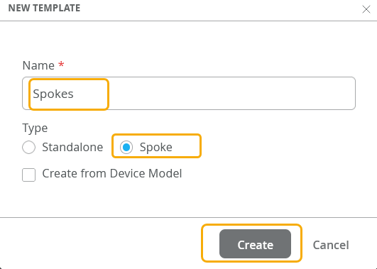
- In the box that appears, enter the name for the template, click
Type and select Spoke, and then click
Create. Figure 1: Select the Template Type
 Note:
Note:You can also create a WAN Edge template by importing a JSON file by using the Import Profile option.
Add WAN Interfaces to the Template
In this task, add two WAN interfaces to the WAN edge template. You can add interfaces in device details page also (In the Juniper Mist portal, click WAN Edges> WAN Edges)
To add WAN interfaces to the template:
- Complete the configuration according to the details provided in Table 2.
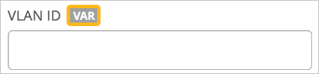
Tip: When working on configuration screens, look for the VAR indicators. Fields with this indicator allow site variables.
The fields with this label also display the matching variables (if configured) as you start typing a specific variable in it. This field lists variables from all sites within the organization.
The organization-wide list of variables can be viewed using GET /api/v1/orgs/:org_id/vars/search?var=*. This list is populated as variables are added under site settings.
Table 2: WAN Interface Configuration Options Fields Description Sample Configuration (WAN Interface 1) Sample Configuration (WAN Interface 2) Name Enter a name for the interface. You can also use a variable. INET MPLS Description Enter the description. You can also use variables for the description. INET-Interface MPLS-Interface WAN Type Select one of the following type: - Ethernet
- DSL
- LTE
Ethernet Ethernet Interface Enter the interface. You can use a variable here. ge-0/0/0 ge-0/0/3 VLAN ID Enter the VLAN ID. You can use a variable here. - - IP Configuration Select IP configuration type: - DHCP
- Static
- PPPoE
DHCP Static IP Address={{WAN1_PFX}}.2
Prefix Length=24
Gateway={{WAN1_PFX}}.1
Source NAT Select the type of source NAT: - Interface
- Pool
- Disabled (if not using it)
Interface Interface Traffic Shaping Select Enabled or Disabled. (Required for Session Smart Routers)
Disabled Disabled Auto Negotiation
Select Enabled or Disabled.
Enabled Disabled MTU
Enter an MTU value between 256 -9192. Default is 1500.
1500 1500
Overlay Hub Endpoint (generated automatically). - hub1-INET, hub2-INET (BFD profile Broadband) hub1-MPLS and hub2-MPLS Figure 2 shows list of WAN interfaces you created.
Figure 2: WAN Interfaces Summary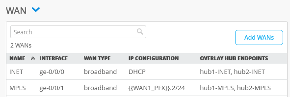
Configure Additional Interface Options
To configure additional settings for WAN Edge ports:
- In the Interface section of the window, select one of the following
options:
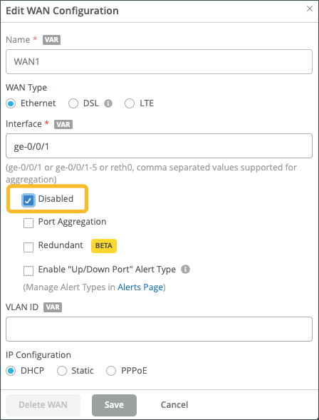
- Disabled - To disable a WAN Edge port. This will
administratively disable the WAN Edge device port for the specified
interface.
There are many reasons why it might be necessary to disable a WAN Edge port. In debugging scenarios, for example, disabling a port and then enabling it again can trigger processes to reset, which can help resolve issues.
You may also want to disable a port when you are staging a connection, but are not quite ready to bring the connection into service, or if you’ve identified a malicious or problematic device, you can disable the port to quickly disable the device until the device can be removed or repaired.
This option is part of interface configuration. If you use this option to disable an aggregated Ethernet (AE) interface or redundant Ethernet (reth) interface, all member links are disabled
- Port Aggregation—To group Ethernet interfaces to form a
single link layer interface. You can use this for Link Aggregation
Control Protocol (LACP) configuration.
Disable LACP—Use thisoption to disable LACP interface.
Enable Force Up—Choose this option prior to onboarding a WAN edge device via Link Aggregation Control Protocol (LACP) interface. When enabled, Enable Force Up forces the first Ethernet interface in the cluster on the peer to the up state, thus allowing the zero-touch provisioning (ZTP) process to retrieve the configuration files needed to complete onboarding.
- Redundant— To enable redundancy.
- Enable "Up/Down Port" Alert Type—To allow the user to receive alerts when the port transitions from up to down or vice-versa.
- Disabled - To disable a WAN Edge port. This will
administratively disable the WAN Edge device port for the specified
interface.
Configure LTE Interface
Juniper Mist SD-WAN allows organizations to integrate LTE connectivity seamlessly. LTE connectivity provides an alternate path for multipath routing; either as a primary path in locations that have no access to circuits or as a path of last resort in the event that the primary circuit has failed.
For example: In a retail store with a primary MPLS connection for business-critical applications. Juniper Mist SD-WAN can add an LTE link as a backup. If the MPLS link experiences issues, Juniper Mist dynamically switches traffic to the LTE link. This ensures continuous connectivity and minimizes disruptions.
On Session Smart Routers, the LTE support is provided through the in-built LTE module that operates on both 3G and 4G networks. See LTE and Dual LTE Configuration on setting up LTE on Session Smart Routers.
To have LTE link for Juniper Mist SD-WAN, you need an LTE interface setup on your Session Smart Routers and SRX Series Firewalls and insert the Subscriber Identity Module (SIM) in the LTE card.
To add an LTE interface as WAN link:
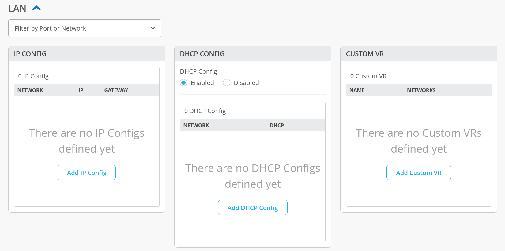
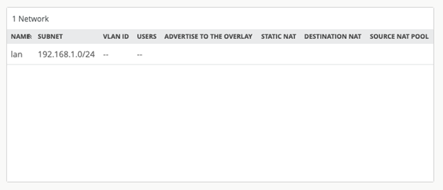
Configure LAN
LAN interface configuration identifies your request source from the name of the network you specify in the LAN configuration.
The LAN configuration section includes the components for IP Configuration, DHCP Configuration, Custom VR, and LAN interface configuration. The LAN configuration section enables more flexibility by allowing you to override each configuration component (such as IP configuration) separately without touching other components.
The LAN Configuration section also provides a filter for you to easily search for configurations per port or network.
To configure LAN:
- Scroll down to the LAN section. Figure 3: Add LAN Interfaces to the Template
- Configure the following settings in the LAN section.
IP configuration—On the IP CONFIG tile, click Add IP Config and configure the following parameters:
- Network—Select an available network from the drop-down.
- IP Address—IPv4 address and prefix length for the interface. You can use the variable also. Example: {{SPOKE_LAN1_PFX}}.1
- Prefix Length—Prefix length for the interface.
- Redirect Gateway—IP address of redirect gateway for Session Smart Routers.
DHCP configuration—Select Enabled option to use DHCP service for assigning IP addresses to the LAN interface. To define a DHCP configuration, click Add DHCP Config and specify the details as described below:
- Network—Select the network from the list of available networks.
- DHCP type—Select DHCP Server or DHCP
Relay. If you chose DHCP server, enter the following
options:
- IP Start—Enter the beginning IP address of the desired IP address range.
- IP End—Enter the ending IP address.
- Gateway—Enter the IP address of the network gateway.
Maximum Lease Time—Specify a maximum lease time for the DHCP addresses. Supported DHCP lease duration ranges from 3600 seconds (1 hour) to 604800 seconds (1 week).
- DNS Servers—Enter IP address of the Domain Name System (DNS) server.
- Server Options—Add following
options:
- Code—Enter the DHCP option code you want to configure the server. The Type field will be populated with the associated value. For example: If you select Option 15 (domain-name), the Type field displays FQDN. You must enter the Value associated to the Type.
Static Reservations—Use this option if you want to statically reserve a DHCP address. Static DHCP IP address reservation involves binding a client MAC address to a static IP address from the DHCP address pool. The following options are available:
Name—A name that identifies the configuration.
MAC Address—The MAC address to be used in the reservation.
IP Address—The IP address to be reserved.
Custom VR configuration—To configure a Custom VR, click Add Custom VR and configure the following parameters:
- Network—Select an available network from the drop-down.
- Name—Enter the name for the routing instance.
LAN interface configuration—Click Add LAN and complete the configuration as described below:
Interface—Enter interface. Example: ge-0/0/3. To configure additional LAN interface options, see Configure Additional Interface Options for LAN.
Note: Mist can automatically perform onboarding through an aggregated interface on the connected WAN edge cluster, but the interface must first be enabled or the connection will fail. For more information, see Configure Additional Interface Options for LAN.Description—Enter the description. Example: LAN-network.
Network—Select from the list of networks that appears. Example: SPOKE-LAN1 (When you do, the remaining configuration will be filled in automatically.)
Tip: When working on configuration screens, look for the VAR indicators. Fields with this indicator allow site variables.The fields with this label also display the matching variables (if configured) as you start typing a specific variable in it. This field lists variables from all sites within the organization.
The organization-wide list of variables can be viewed using GET /api/v1/orgs/:org_id/vars/search?var=*. This list is populated as variables are added under site settings.
Configure Traffic-Steering Policies
Just like with hub profiles, traffic steering in a Juniper Mist network is where you define the different paths that application traffic can take to traverse the network. The paths that you configure within traffic steering also determine the destination zone.
To configure traffic-steering policies:
- Complete the configuration according to the details provided in Table 4.
Table 4: Traffic-Steering Policies Summary Fields Traffic Steering Policy 1 Traffic Steering Policy 2 Name SPOKE-LANS Overlay Strategy Ordered ECMP PATHS (For path types, you can select the previously created LAN and WAN networks as endpoints.) - Type—LAN
- Network —SPOKE-LAN1
- Type— WAN
- Network —
- hub1-INET
- hub2-INET
- hub1-MPLS
- hub2-MPLS
Figure 4 shows the list of traffic steering policies you created.
Figure 4: Traffic-Steering Policies Summary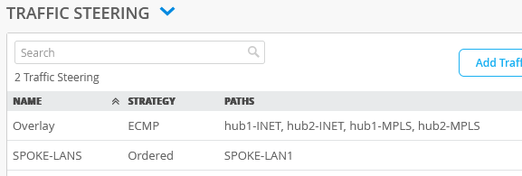
Configure Application Policies
In a Mist network, application policies are where you define which network and users can access which applications, and according to which traffic-steering policy. The Networks/Users settings determine the source zone. The Application + Traffic Steering settings determine the destination zone. Additionally, you can assign an action of Permit or Deny. Mist evaluates and applies application policies in the order in which you list them.
Consider the traffic-flow requirements in Figure 5. The image depicts a basic initial traffic model for a corporate VPN setup (third spoke device and second hub device are not shown).
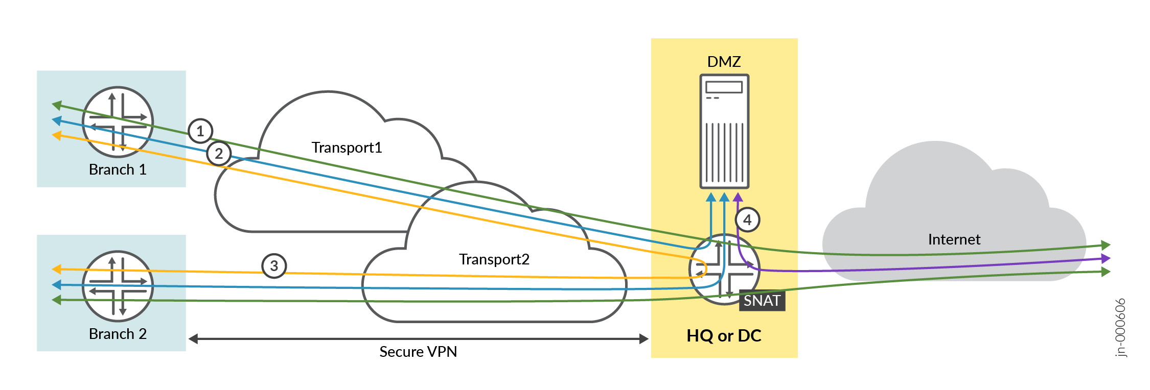
To meet the preceding requirements, you need to create the following application rules:
Policy 1—Allows traffic from spoke sites to the hub. In this case, the destination prefix used in address groups represents the LAN interface of two hubs.
Policy 2—Allows spoke-to-spoke traffic through the corporate LAN through an overlay.
Note:This may not be feasible in the real world except on expensive MPLS networks with managed IPs. Managed IPs send traffic directly to the other spoke. This type of traffic usually flows through a hub device
Policy 3—Allows traffic from both the hub and the DMZ attached to the hub to the spoke devices.
Policy 4—Allows Internet-bound traffic to flow from spoke devices to the hub device. From there, the traffic breaks out to the Internet. In this case, the hub applies source NAT to the traffic and routes traffic to a WAN interface, as defined in the hub profile. This rule is general, so you should place it after the specific rules. Juniper Mist cloud evaluates and applies application policies in the order in which the policies are listed.
Order of application policies do not have any effect on Session Smart Router configuration. As good practice, we recommend you to place global rules towards the end of the policy rules list.
Traffic steering on each rule is not a mandatory for Session Smart Routers. When you use Session Smart Router, the system announces all routes on each LAN interface using the iBGP-based route distribution.
Use the same name for network on both sides for Session Smart Router for traffic to traverse between a hub and a spoke. The network name for the Session Smart Router must be identical to the security tenant used for traffic isolation. Because of this, the network name must match on both sides.
To create an application policy:
- Complete the configuration according to the details provided in Table 5
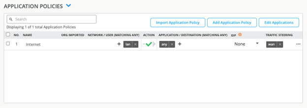
Table 5: Application Policies Configuration S.No Rule Name Network Action Destination Steering 1 Spoke-to-Hub-DMZ SPOKE-LAN1 Pass HUB1-LAN1 + HUB2-LAN1 Overlay 2 Spoke-to-Spoke-via-Hub SPOKE-LAN1 Pass SPOKE-LAN1 Overlay 3 Hub-DMZ-to-Spoke HUB1-LAN1 + HUB2-LAN1 Pass SPOKE-LAN1 SPOKE-LANS 4 Internet-via-Hub-CBO SPOKE-LAN1 Pass ANY Overlay Figure 6 shows the list of application policies you created.
Figure 6: Application Policies Summary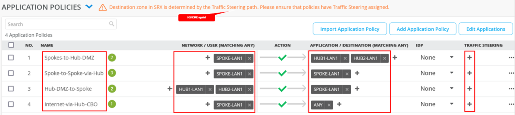
Assign Spoke Templates to Sites
The template now exists in the Juniper Mist cloud as an object that can be attached to one or more sites.
You can apply the same template to multiple sites.
If a site already has a template assigned to it, assigning another template will replace the existing template (in other words, one site cannot have two templates).
To assign the spoke template to site:
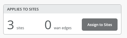
- Scroll to the top of the WAN Edge Templates page and click
Assign to Sites under Spokes panel. Figure 7: Assign Spoke Templates to Sites

- In the Assign Template to Sites, select the required
sites. Figure 8: Select Sites to Assign Spoke Templates
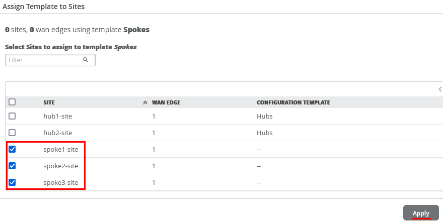
- Click Apply. Figure 9: WAN Edge Templates Applied to Sites
Configure Device-Specific WAN Edge Templates
Device configuration is simplified with WAN Edge Templates following your device onboarding process. These WAN Edge templates can be customized to unique deployments across all edge devices. Juniper Networks Mist AI is positioned uniquely in the industry as Mist AI WAN Edge templates can be applied to any model, regardless of vendor. Additionally, WAN Edge templates can mix and match different models under a single template, streamlining your configuration and deployment phase.
To manually configure your WAN Edge templates for the Session Smart Router, see Configure a WAN Edge Template.
Device-Specific WAN Edge Templates
There is a significant benefit to leveraging Juniper Networks hardware with Mist AI SD-WAN. Configuration is simplified for many Juniper Networks® Session Smart™ Routers, and Juniper Networks® SRX Series Firewalls, which have device-specific templates that automatically assign WAN and LAN interfaces and define LAN Networks for connectivity.
These templates are unique for each device model. With zero manual input after device selection and naming the WAN Edge, a user’s specified WAN Edge device is pre-populated with the values.
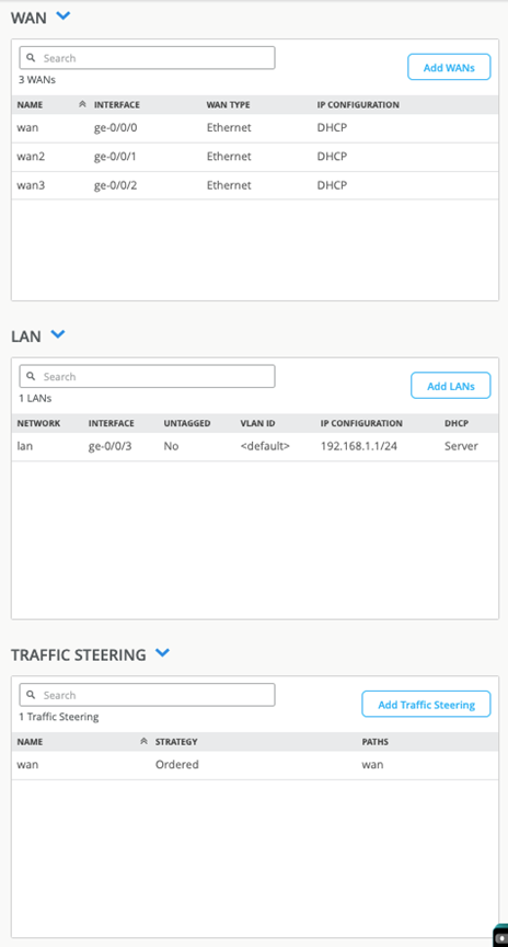
For example, Figure 10 shows that the SSR120 WAN Edge template generates several values, including Ethernet interfaces for LAN and WAN with relevant DHCP and IP values:
- wan ge-0/0/0
- wan2 ge-0/0/1
- wan3 ge-0/0/2
- lan ge-0/03
Additionally, we see in Figure 10 that the Juniper Mist portal populates a traffic steering policy. This enables Juniper Mist to send traffic over our wan connection to an any Mist Application with a quad zero catch-all destination.
Upon applying a WAN Edge template, application policies, networks, and applications receive automatic updates as shown in Figure 11, Figure 12, and Figure 13.
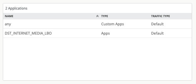
Juniper Mist AI SD-WAN includes the following device models with pre-configured WAN Edge templates for Session Smart Routers:
- SSR120
- SSR130
- SSR1200
- SSR1300
- SSR1400
- SSR1500
The WAN Edge device specific templates provide basic network configuration in a single step and allow for re-usable and consistent configuration for Session Smart Router and SRX Series Firewall device you deploy. The template provides device-specific, pre-configured WAN interfaces, LAN interfaces, a traffic steering policy, and an application policy. All you have to do is name the template and select the device type.
To select a device-specific WAN Edge template:
- In the Juniper Mist portal, select Organization > WAN > WAN Edge Templates.
- Select Create Template in the upper right corner to open a new template page.
- Enter the name for the template.
- Click the Create from Device Model check-box.
- Select your device model from the drop-down box. Figure 14: Configure Device-Specific WAN Edge Template
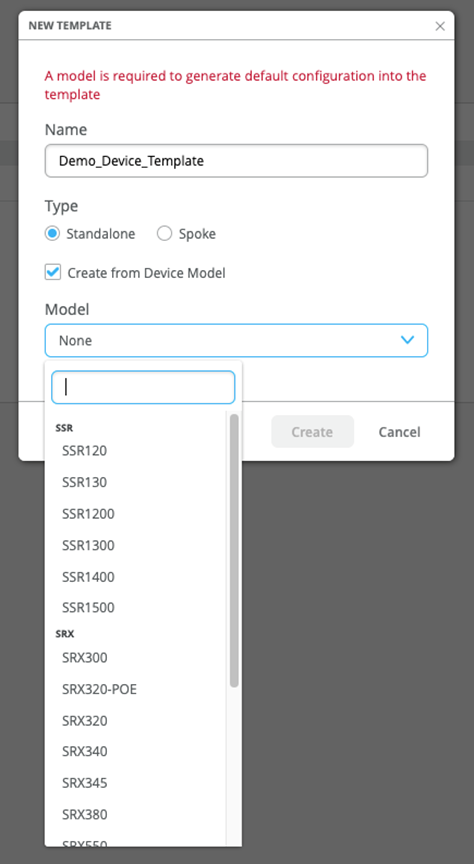
- Click Create.
Juniper Mist UI displays the completed device template. You now have a working WAN Edge template that you can apply to many sites and devices across your organization.
Assign to Site
With your template set up, you need to save and assign it to the site where your WAN edge device will be deployed.
- Click the Assign to Site button at the top of the template page.
- Select a site from the list where you want the template applied.
- Click Apply.
- Finally, all that remains is to associate the device with your Site: Onboard Session Smart Routers for WAN Configuration
