- play_arrow Overview
- play_arrow Platform Considerations
- play_arrow WAN Configuration for SRX Series Firewalls
- WAN Assurance Configuration Overview
- Configure Sites and Variables for SRX Series Firewalls
- Configure Applications for SRX Series Firewalls
- Configure Networks for SRX Series Firewalls
- Configure Application Policies on SRX Series Firewalls
- Configure Hub Profiles for SRX Series Firewalls
- Configure WAN Edge Templates for SRX Series Firewalls
- Routing Configuration on SRX Series Firewalls
- Onboard SRX Series Firewalls for WAN Configuration
- IDP-Based Threat Detection for SRX Series Firewalls
- Enable Application Visibility on SRX Series Firewalls
- Monitor the Service Status of SRX Series Firewalls
- Upgrade a WAN Edge SRX Series Firewalls
- Configure a Custom VR for SRX Series Firewalls
- Revoke DHCP Lease on a WAN Edge Device
- Reserve DHCP IP Address
- play_arrow WAN Assurance Design
- play_arrow Secure Edge Connector
- play_arrow Cellular Edges
- play_arrow Monitor and Troubleshoot
- WAN Assurance Monitoring, SLE, and Troubleshooting Overview
- Monitor SRX Series Firewall Deployed as WAN Edge
- Monitor Session Smart Router Deployed as WAN Edge
- Service-Level Experiences for Session Smart Router Deployed as WAN Edge
- Troubleshoot Session Smart Router Deployed as WAN Edge
- Speed Tests for Session Smart Router Deployed as a WAN Edge (BETA)
- Dynamic and Manual Packet Captures
- Troubleshoot SRX Series Firewalls
- Replace a WAN Edge Device
- WAN Edge Testing Tools
Configure Networks for Session Smart Routers
Networks are sources of the request in your Juniper WAN Assurance design. On the Juniper® Session Smart™ Router, networks create tenants in the background for SVR and the Session Smart Router identifies tenants at the logical interface (network interface). LAN and WAN interface configurations identify your tenant (request source).
Once you have created networks in the Juniper Mist™ cloud portal, you can use networks across the entire organization in the portal. WAN Assurance design uses networks as the source in the application policy.
To configure a Network:
- Click Add.
Figure 1 shows the list of newly created networks.
Figure 1: Networks Summary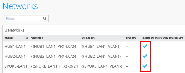
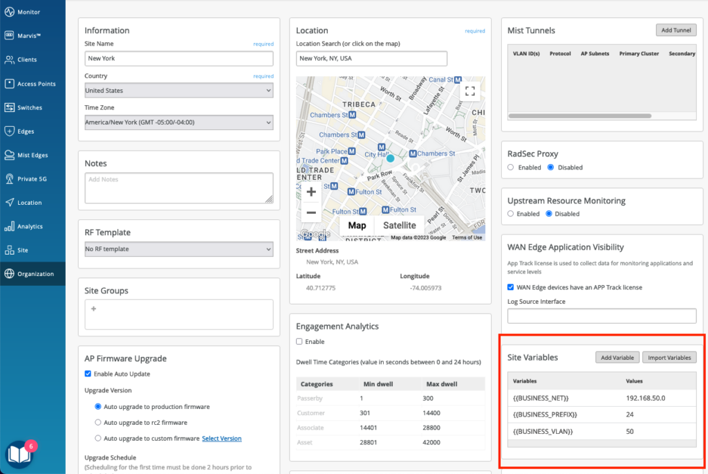
Site Variables
You can configure the site variables on a per-site basis. When planning a network holistically, you can configure specific WAN edge devices and WAN edge clusters using templates.
Site variables allow you to use the same network definition with different values for each site without having to define multiple networks. Variables have the format {{variable_name}}.
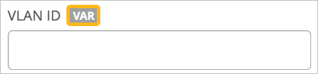
The fields with this label also display the matching variables (if configured) as you start typing a specific variable in it. This field lists variables from all sites within the organization.
The organization-wide list of variables can be viewed using GET /api/v1/orgs/:org_id/vars/search?var=*. This list is populated as variables are added under site settings.
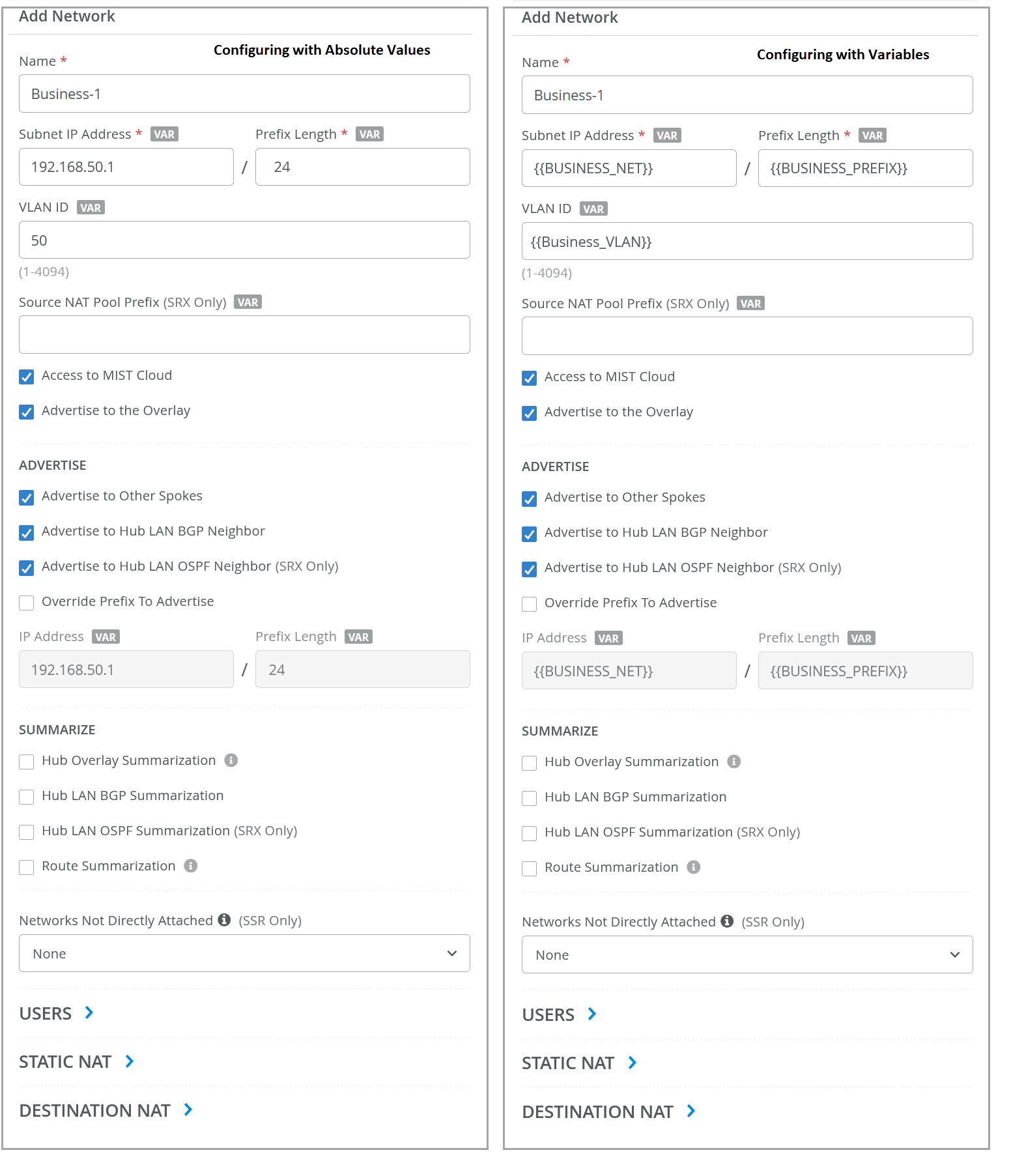
Defining networks with variables is common practice in WAN edge template configuration.
Figure 2 shows two samples of configuration of a network using absolute values and using site variables.
You can define the site variables in Organization > Admin> Site Configuration pane.
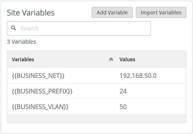
This task uses variables for the VLAN ID and subnet IP address. Site variables that contain the first three octets substitute the subnet IP address variable values as shown in Figure 4.