Unpacking and Mounting the QFX5230-64CD Switch
Unpacking a QFX5230-64CD Switch
The QFX5230-64CD switch is a rigid sheet-metal structure that houses the hardware components. A QFX5230-64CD switch is shipped in a cardboard carton, secured with foam packing material.
The QFX5230-64CD switch is maximally protected inside the shipping carton. Do not unpack the switch until you are ready to begin installation.
To unpack a QFX5230-64CD switch:
- Move the shipping carton to a staging area as close to the installation site as possible, but where you have enough room to remove the system components.
- Position the carton so that the arrows are pointing up.
- Open the top flaps on the shipping carton.
- Pull out the packing material holding the switch in place.
- Verify the contents against the inventory included in the box. Table 1 lists the inventory of components supplied with a QFX5230-64CD switch.
- Save the shipping carton and packing materials in case you need to move or ship the switch later.
|
Component |
Quantity |
|---|---|
|
Chassis |
1 |
|
Fan modules - QFX5230-64CD-FANAO |
4, factory installed |
|
Power supplies - JNP-3000W-AC-AFO |
2, factory installed |
|
Rack mount kit for QFX5230-64CD
The order number for a spare rack mount kit is QFX5230-2RU-4PRMK. |
1 2 2 624 |
|
SAF-D-Grid power cords with plugs appropriate to your geographical location (AC systems only) |
2 |
|
Documentation roadmap card |
1 |
|
Warranty |
1 |
Update Base Installation Data
Update the installation base data if any addition or change to the installation base occurs or if the installation base is moved. Juniper Networks is not responsible for not meeting the hardware replacement SLA for products that do not have accurate installation base data.
Update your installation base at https://supportportal.juniper.net/s/CreateCase .
Mounting a QFX5230-64CD Switch in a Rack or Cabinet
You can mount QFX5230-64CD switches only on a four-post 19-in. rack or cabinet using the rack mount kit provided with the switch.
This topic describes how to mount a QFX5230-64CD switch in a four-post rack.
- Before You Begin Rack Installation
- Mount your Device by Using the QFX5230-2RU-4PRMK Rack Mount Kit on a 4-Post Rack
Before You Begin Rack Installation
Before you begin mounting a QFX5230-64CD switch in the rack or cabinet:
A QFX5230-64CD switch requires two people for installation, one person to lift the device into place and another person to attach the device to the rack. If you are installing the QFX5230-64CD switch above 60 in. (152.4 cm) from the floor, you can remove the power supplies and fan modules to minimize the weight before attempting to install the device.
If you are mounting multiple devices on a rack, mount the device in the lowest position of the rack first. Proceed to mount the rest of the devices from the bottom to the top of the rack to minimize the risk of the rack toppling.
Mount your Device by Using the QFX5230-2RU-4PRMK Rack Mount Kit on a 4-Post Rack
Ensure that you have the following tools and parts available:
-
An ESD grounding strap—not provided.
-
A pair of side mounting brackets that attach to the chassis—provided with the rack mount kit.
-
A pair of front and rear mounting rails that attach to the rack posts—provided with the rack mount kit.
To mount the device on a four-post rack:
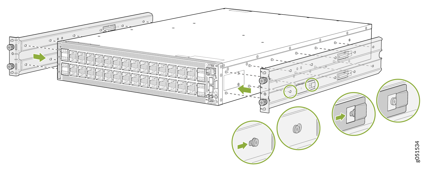
-
To attach the side mounting brackets to the chassis, align the keyholes
on the mounting brackets over the shoulder screws on the chassis. Slide
the mounting brackets toward the rear of the chassis.
Figure 1: Attach the Side Mounting Brackets
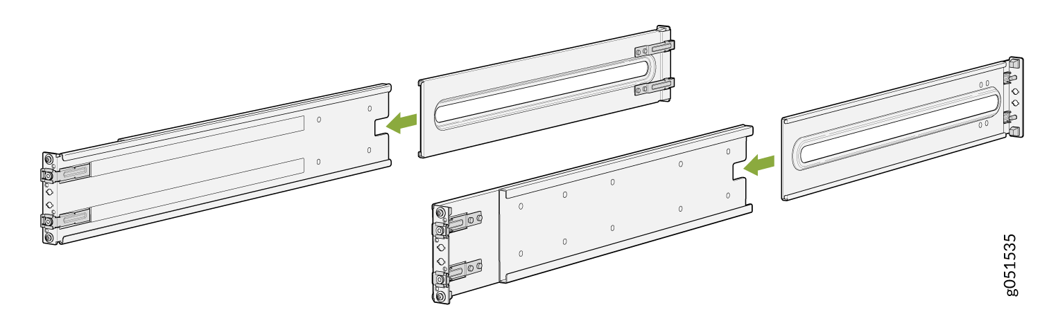
-
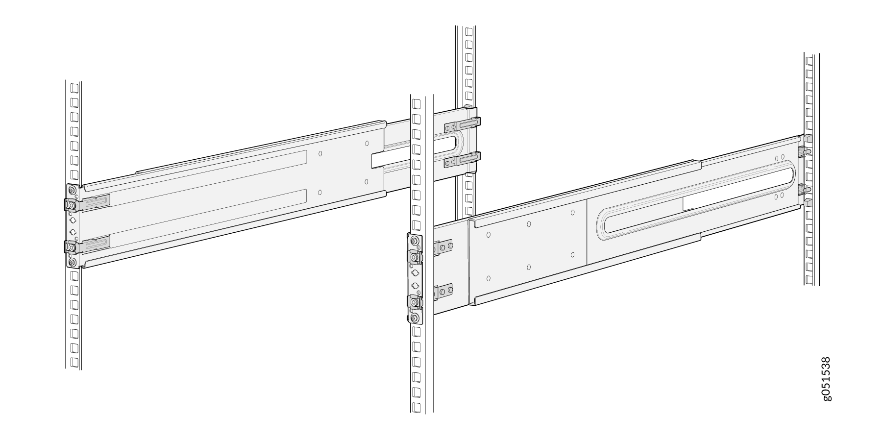
Assemble the mounting rails by sliding the rear floating rails into the
front rails.
Figure 2: Assemble the Mounting Rails
-
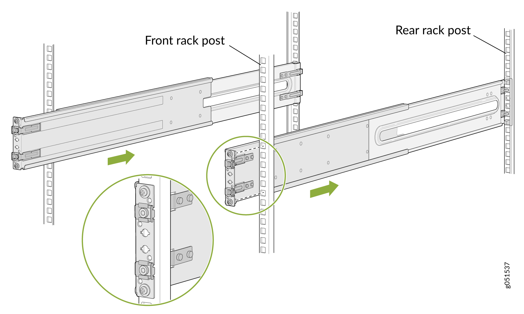
Install the mounting rails on the rack:
-
Align the guide blocks of the rear mounting rails with the
rear-post holes. Pull the rear mounting rails toward the front
of the rack to lock the rails in place. You will hear a distinct
click sound when the latch locks into the corresponding rack
holes.
Figure 3: Install the Rear Mounting Rails
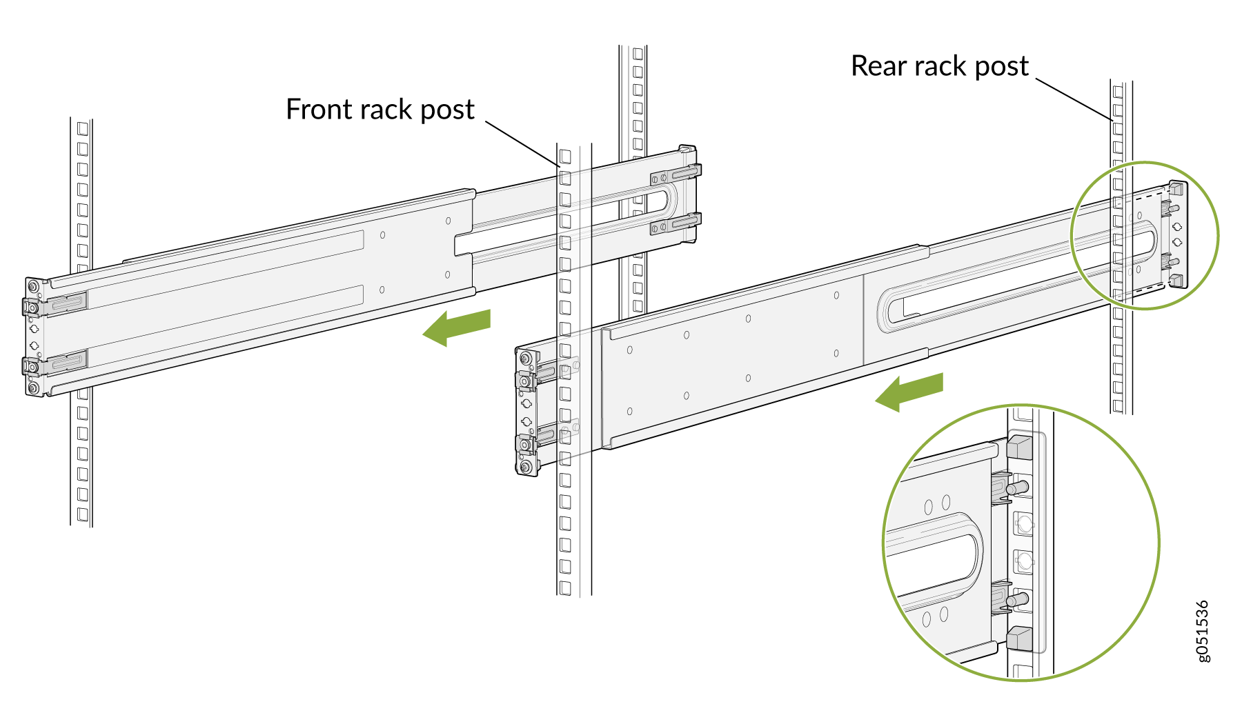
-
Align the guide blocks of the front mounting rails with the
front-post holes. Push the front mounting rails toward the rear
of the rack to lock the rails in place. You will hear a distinct
click sound when the latch locks into the corresponding rack
holes.
Figure 4: Install the Front Mounting Rails
-
Align the guide blocks of the rear mounting rails with the
rear-post holes. Pull the rear mounting rails toward the front
of the rack to lock the rails in place. You will hear a distinct
click sound when the latch locks into the corresponding rack
holes.
-
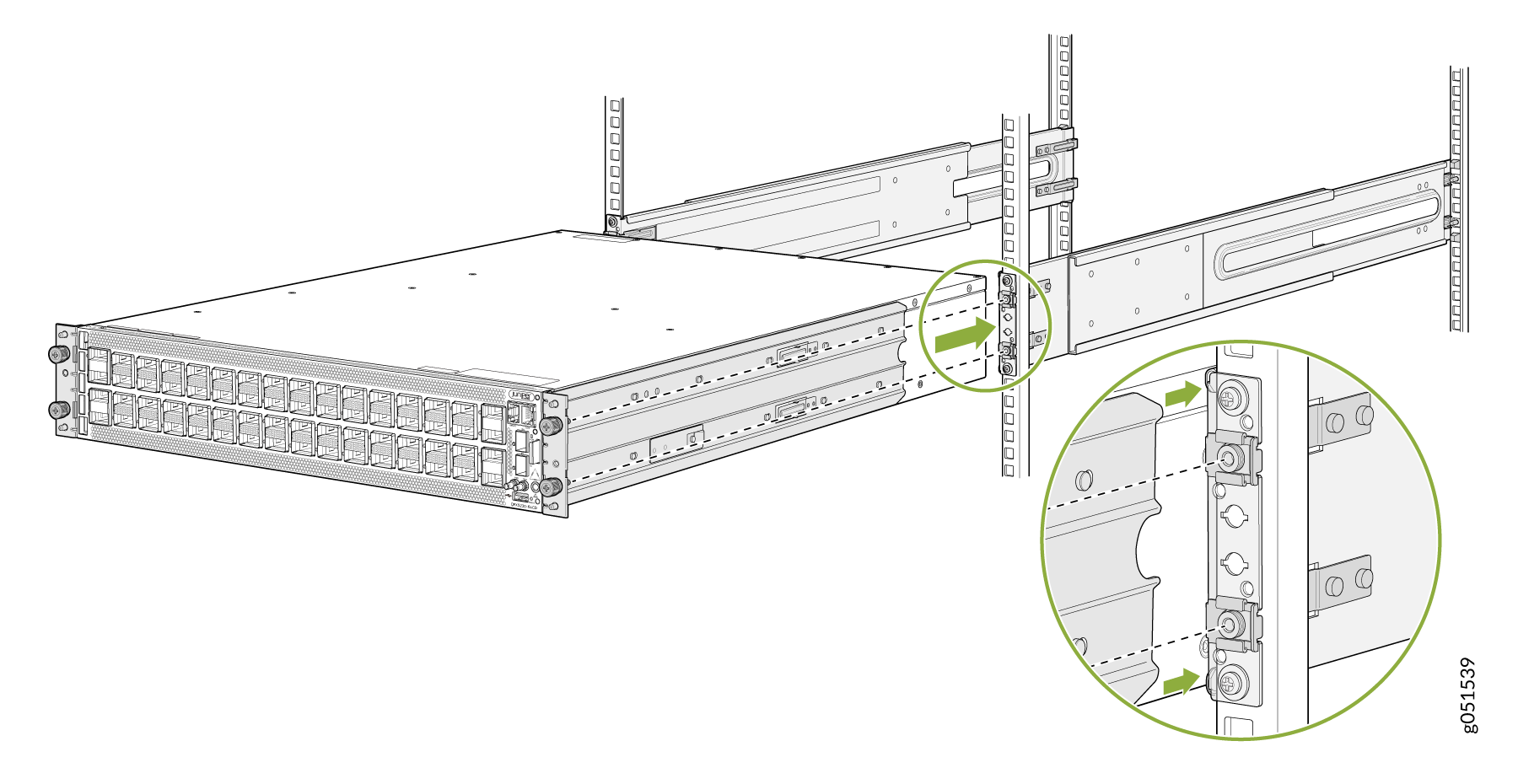
Lift the device and position it in front of the rack, aligning the side
mounting-brackets with the mounting rails. Slide the device into the
channels of the rack mounting rails.
Figure 5: Slide the Mounting Rail into the Rack
-
Push the chassis.
Figure 6: Push the Chassis into the Rack
-
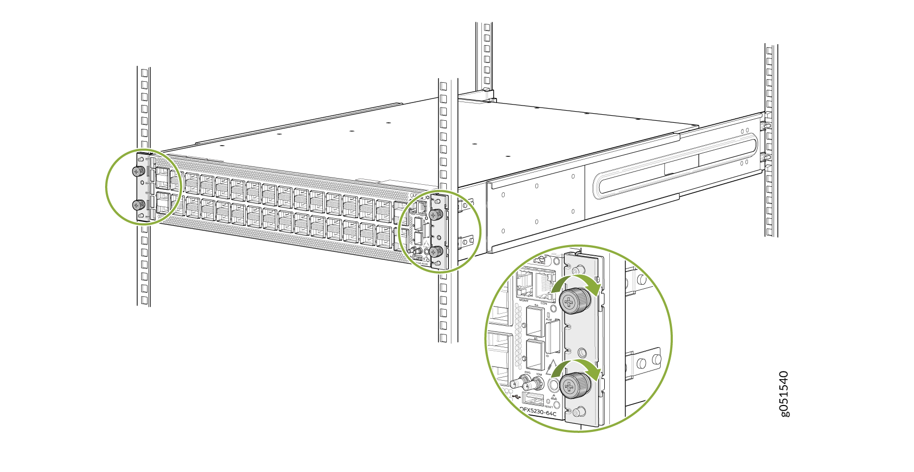
Secure the chassis to the rack and tighten the thumbscrews.
Figure 7: Tighten the Thumbscrew