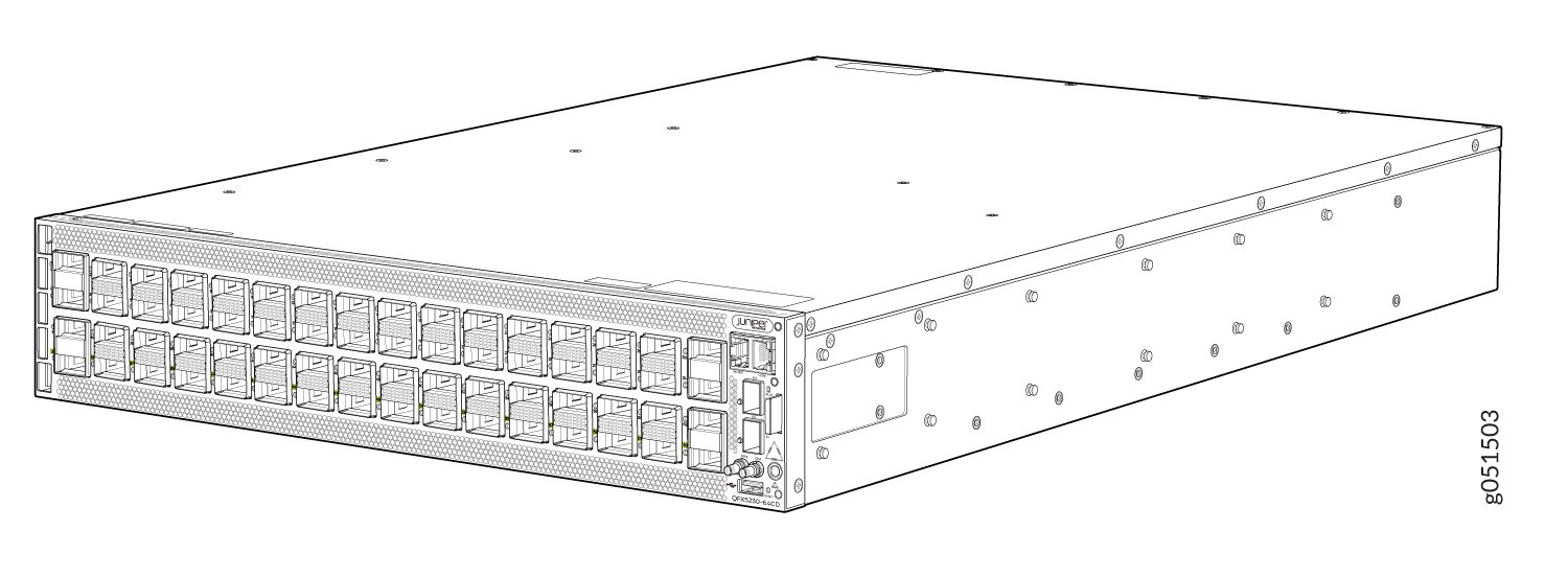
QFX5230-64CD Port and Management Panel
QFX5230-64CD Port Panel
Overview
The QFX5230-64CD's port panel is made up of the management panel and 64 high-density 400-Gigabit Ethernet quad small form-factor pluggable (QSF-DD) ports. Each port has the option to be configured for 400G, 200G, 100G, 50G, 40G, 4x25G, or 4x10G speeds. It has two SFP+ ports as well. Its design aims to minimise power consumption and latency.The typical configuration for QFX5230-64CD) is shown below:
- 48x 400G QSFP56-DD ports + 16x 400G-ZR/ZR-M QDD ports
- 2 x 10G SFP+ ports
- 1 x 10M/100M/1G RJ45 Management port
- 1 x RJ45 Console port
- 1x USB 2.0
- 10MHz & 1PPS SMB output
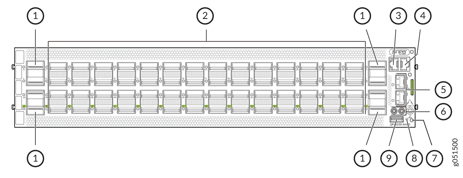
1 — QSFP56-DD 400 GbE ports | 6 — Clock input and output connectors (10MHz and 1PPS) |
2 — QSFP56-DD 400 GbE ports | 7 — ESD grounding point |
3 — RJ-45 system management port | 8 — Reset button (do not use unless directed by JTAC) |
4 — RJ-45 console port | 9 — Type A USB port |
5 — SFP+ ports |
The 16 ports marked in green, from 33 through 63, denote the ports that support 400G-ZR and 400G-ZRM QDD optics. If these optics are plugged into other ports, they don't function and the system triggers an alarm.
QFX5230-64CD Network LEDs
To show link status, activity on the link, or a fault condition, each QSFP56-DD network port has a single bi-colored LED. In an unchannelized port, the port link status is shown by the LED on the left.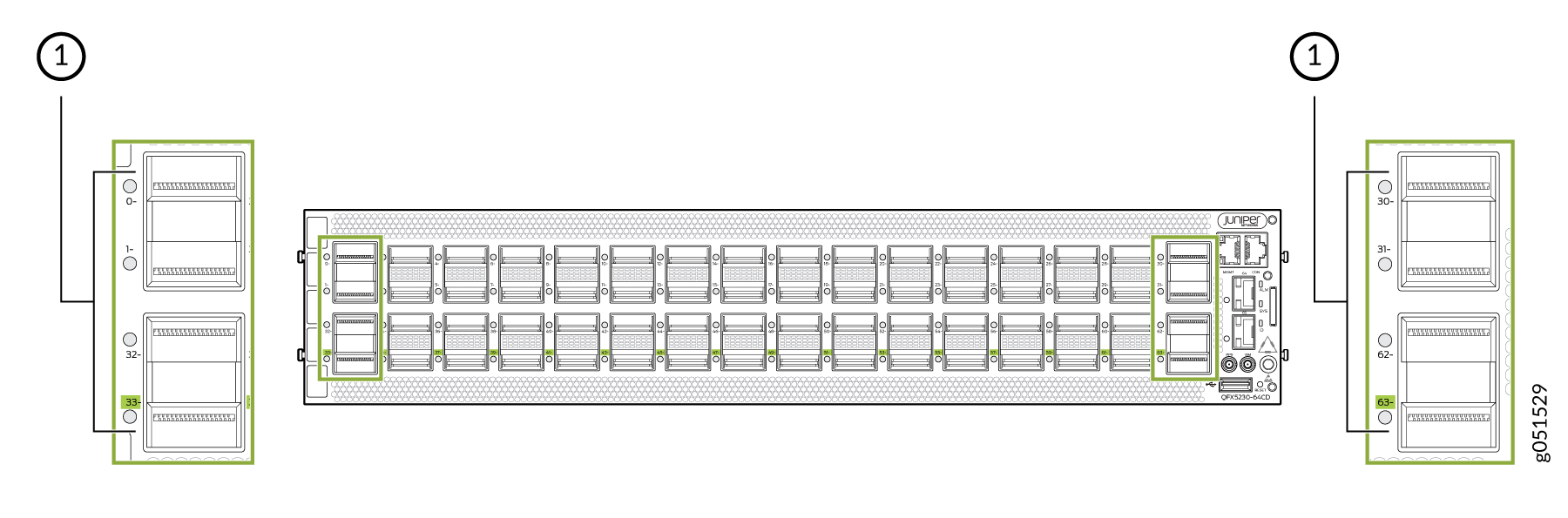
1 — LEDs that indicate status and channelization |
The ports that are marked in green indicate support for 400G-ZR and 400G-ZRM optics.
Each port has an individual status LED on the left. The port status LED has four states signaled by the color/LED state: Off, Green, Amber, and Red.
| Transceiver Inserted | Normal | Breakout Cable Configuration State | Explicitly Disabled | Port State | Port Location On | Lane Display |
|---|---|---|---|---|---|---|
| Any | Green | No Breakout | No | Up | Blinking green | Not Applicable |
| Yes | Red | No Breakout | No | Down, Transceiver hardware failure | Blinking red | Not Applicable |
| Yes | Off | No Breakout | No | DOWN, Loss of signal detected (LOS) | Blinking green | Not Applicable |
| Any | Amber | No Breakout | No | DOWN, any other fault except LOS and transciever hardware failure | Blinking amber | Not Applicable |
| Any | Amber | No Breakout | Yes | The port is disabled in the CLI | Blinking amber | Not Applicable |
| No | Off | Any | No | Anything except disabled port, but no transciever is present | Blinking green | Not Applicable |
| Any | Green | Breakout | No | At breakout ports are Up | Blinking green | Blinking Green |
| Yes | Red | Breakout | No | Hardware failure, transceiver init error at the port level | Blinking red | Blinking Red |
| Yes | Off | Breakout | No | All breakout ports are DOWN with LOS | Blinking green | Blinking Green |
| Any | Amber | Breakout | Any | In all other cases the port LED color is Amber | Blinking amber | Blinking Amber |
QFX5230-64CD Management Panel and LEDs
The management panel allows you to have a management channel into the switch that is separate from production traffic. The management panel of the QFX5230-64CD is located to the right of the network ports.
You can find the following LEDs on the management panel:
-
Chassis status LEDs
-
RJ-45 Console and Management Port LEDs
The following sections explain how to interpret these LEDs.
QFX5230-64CD Chassis Status LEDs
QFX5230-64CD has three LEDs that indicate system status. You can find these LEDs on the right of the SFP+ ports.
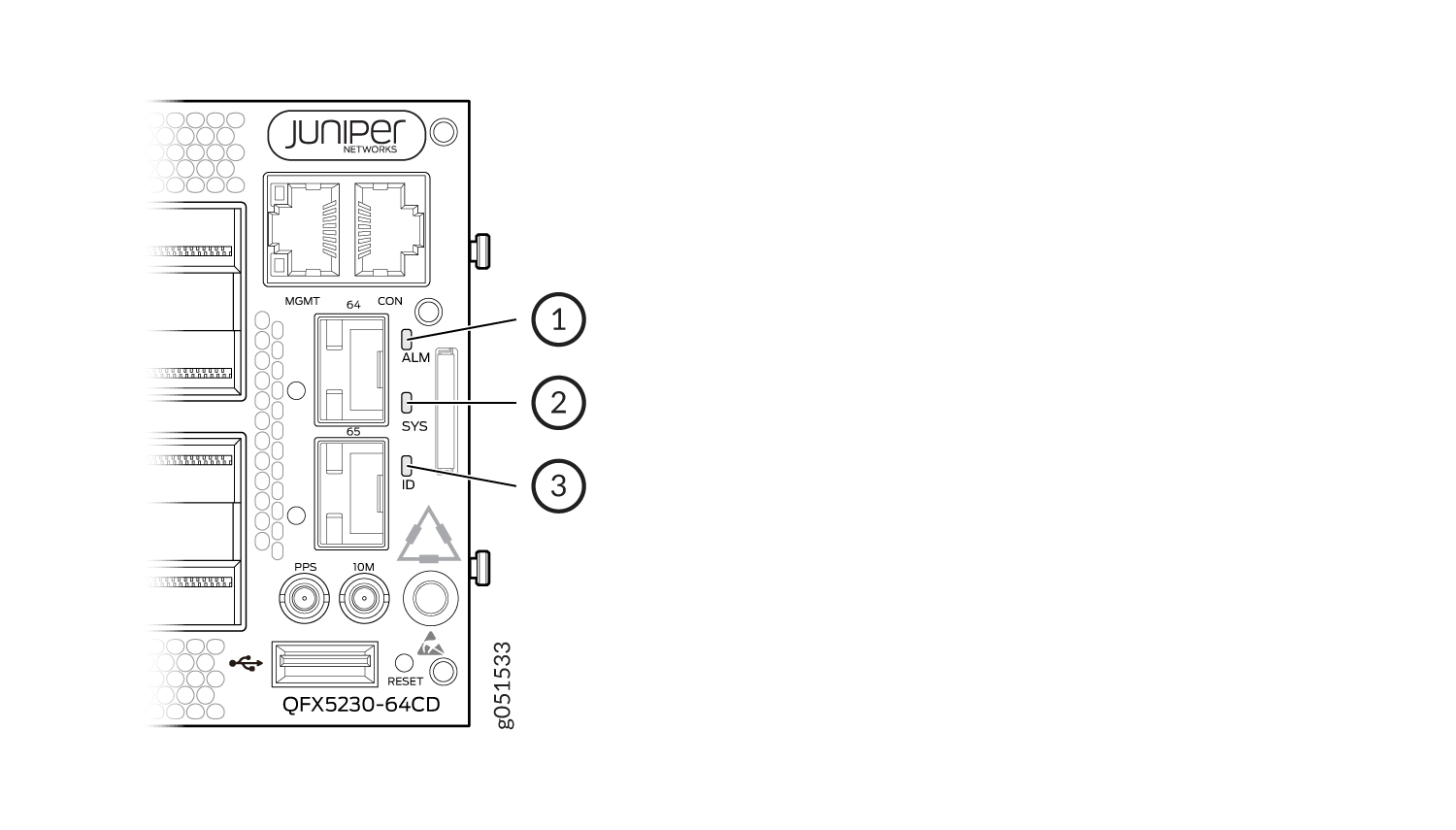
1 — Chassis alarm or fault | 3 — Beacon |
2 — System status |
Table 2 describes the chassis status LEDs on a QFX5230-64CD, the colors and states, and the status they indicate.
| Name | Color | State | Description |
|---|---|---|---|
| ALM–Alarm | Unlit | Off | The switch is halted or there is no alarm. |
| Red | On steadily | A major system or hardware fault has occurred, such as a temperature alarm, power failure, or media failure. The device has halted. Power off the device by setting the AC power source outlet to the OFF (O) position, or by unplugging the AC power cords. Correct any voltage or site temperature issues, and allow the switch to cool down. Power on the QFX5230-64CD. Monitor the power supply and fan LEDs to help determine where the error is occurring. | |
| Yellow | On steadily | A minor system level alarm has occurred, such as a software error or a missing rescue configuration. Power off the device by setting the AC power source outlet to the OFF (O) position, or by unplugging the AC power cords. Power on the QFX5230-64CD and monitor the status LEDs to ensure that Junos OS Evolved boots properly. | |
| Amber (Red and Yellow) | Blinking | A major and minor system level alarm has occurred, and requires immediate action. | |
| SYS–System | Unlit | Off | The device is powered off or halted. |
| Green | Blinking | Junos OS Evolved software is getting loaded on the device. This LED is also activated when the system shutdown is in progress. | |
| Green | On steadily | Junos OS Evolved software is loaded on the device and system is operational. | |
| ID–Identification | Unlit | Off | The beacon feature is not enabled
on the switch. Enable this feature by using the
request chassis beacon fpc 0 on
operational CLI command. |
| Blue | Blinking | The beacon feature is enabled on
the switch. Disable this feature by using the
request chassis beacon fpc 0 off
operational CLI command. |
|
|
Tip:
To find the status of the beacon, use the
user@host> show chassis beacon fpc 0
    FPC 0                OFF
|
|||
You can view the colors of the three LEDs remotely through the CLI by issuing
the operational mode command show chassis led.
This is a sample output.
user@host> show chassis led
 -----------------------------------
LEDs status:
    Alarm LED : Blinking Red/Yellow
    Beacon LED: Off
    System LED: Green

Interface               STATUS LED      LINK/ACTIVITY LED
---------------------------------------------------------
et-0/0/0                N/A             Off
et-0/0/1                N/A             Off
et-0/0/2                N/A             Off
et-0/0/3                N/A             Off
et-0/0/4                N/A             Off
et-0/0/5                N/A             Off
et-0/0/6                N/A             Off
et-0/0/7                N/A             Off
et-0/0/8                N/A             Off
et-0/0/9                N/A             Off
et-0/0/10               N/A             Green