Connect SRX4700 to Power
This section takes you through numerous steps and safety precautions to be followed while connecting power to the SRX4700, to prevent equipment damage and personal injury.
To meet safety and electromagnetic interference (EMI) requirements and to ensure proper operation, you must connect the SRX4700 to an earth ground before you connect it to power.
Tools and Parts Required to Ground and Connect the SRX4700 to Power
To ground and to provide power to the firewall, you need the following tools and parts:
-
Phillips (+) screwdrivers, Number 1 and Number 2
-
A socket nutdriver
-
A 2.5-mm flat-blade (–) screwdriver
-
A torque-controlled driver, with a maximum torque capacity of 23 lbf-in. (2.6 Nm) to 25 lbf-in. (2.8 Nm) for tightening screws to terminals on each power supply unit (PSU) on a DC-powered firewall.
CAUTION:The maximum torque rating of the terminal screws on the DC power supply is 23 lbf-in. (2.6 Nm) through 25 lbf-in. (2.8 Nm). If you apply excessive torque, you might damage the terminal screws. Use only a torque-controlled driver to tighten screws on the DC power supply terminals. Use an appropriately sized driver, with a maximum torque capacity of 6 lb-in. (0.6 Nm) or less. Ensure that the driver is undamaged and properly calibrated and that you have been trained in its use. You might want to use a driver that is designed to prevent overtorque when the preset torque level is achieved.
-
Electrostatic discharge (ESD) grounding wrist strap.
Connect Earth Ground to the SRX4700
To ground the SRX4700 Firewall:
Ensure that you have the following parts and tools available:
-
Grounding cable for your firewall (not provided)—The grounding cable must be 6 AWG (13 mm²), minimum 90° C wire, or as permitted by the local code.
-
Grounding lug for your grounding cable (not provided)—The grounding lug required is a Panduit LCD6-14AF-L or equivalent.
-
Two pan head M5 x10 mm screws with integrated split washers (not provided)—The screws and washers are used to secure the grounding lug to the protective earthing terminal.
-
Wrap and fasten one end of the electrostatic discharge (ESD) cable
grounding strap around your bare wrist, and connect the other end to a site
ESD point or to the ESD point on your firewall.
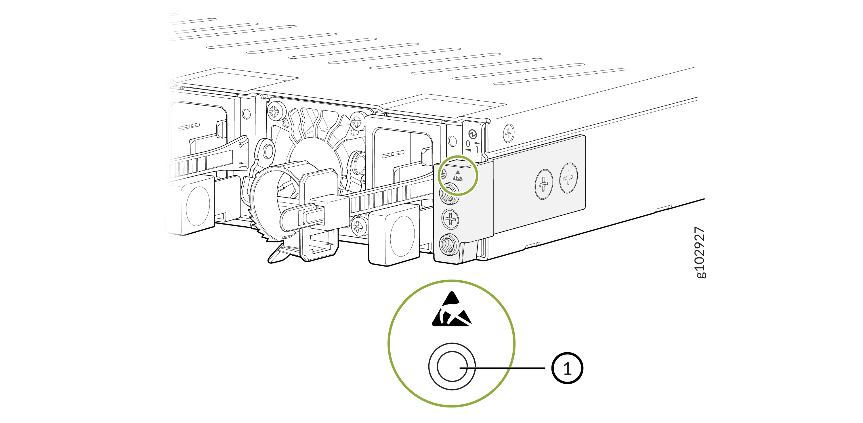
1
Chassis ESD Point
-
Place the grounding cable terminal attached to the grounding cable over the
grounding point.
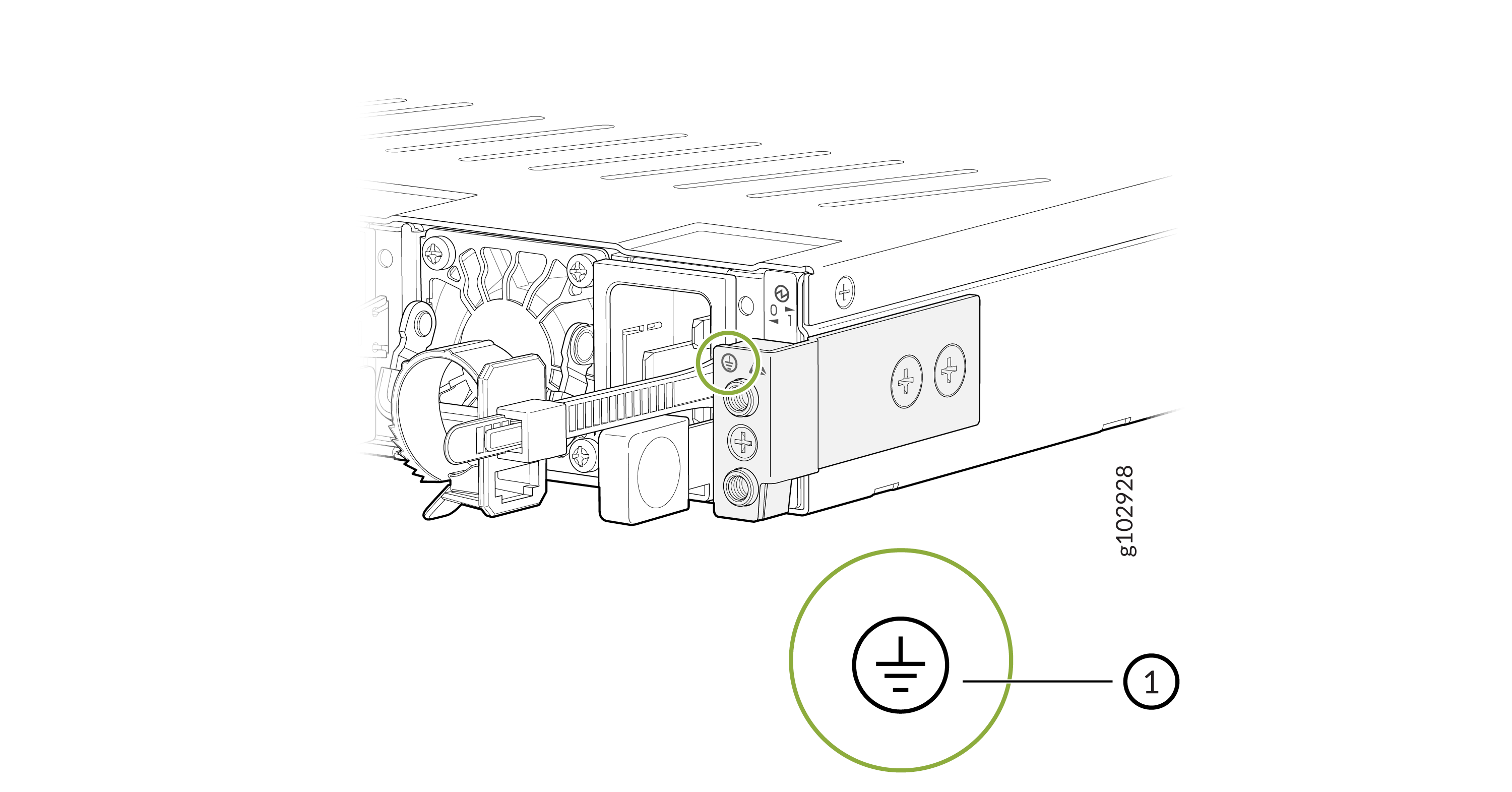
1
Chassis grounding point
-
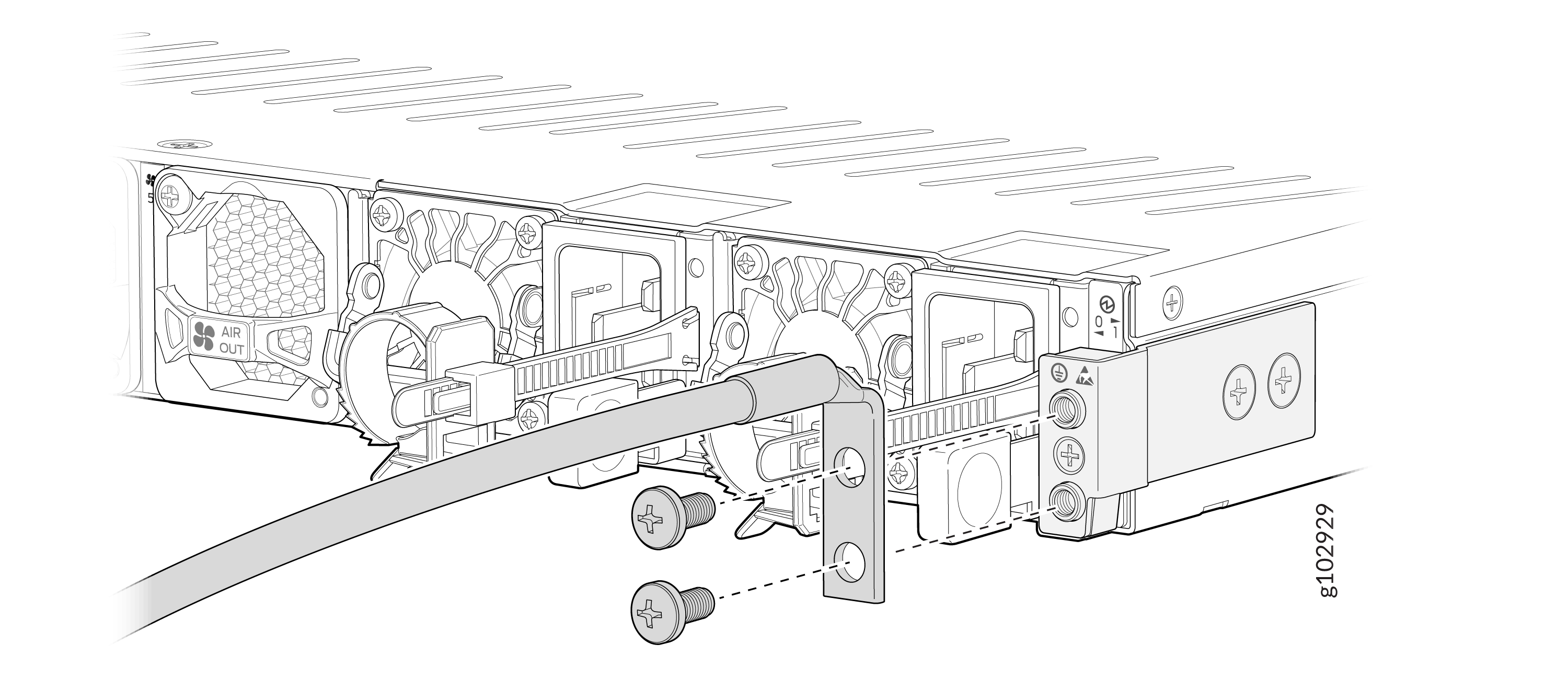
Secure the grounding cable terminal to the grounding point using the M5
screws.
Connect AC Power to the SRX4700
The AC PSUs in an SRX4700 are hot-removable and hot-insertable field-replaceable units (FRUs). You can remove and replace the AC PSUs without powering off the firewall or disrupting its functions.
You must not mix AC and DC PSUs in the same chassis.
Before you begin to connect AC power to the firewall:
-
Ensure that you have connected the chassis to an earth ground.
Warning:Before you connect power to the firewall, a licensed electrician must attach a cable terminal to the grounding and power cables that you supply. A cable with an incorrectly attached terminal can damage the firewall (for example, by causing a short circuit).
To meet safety and electromagnetic interference (EMI) requirements and to ensure proper operation, you must connect the chassis to an earth ground before you connect it to power. For installations that require a separate grounding conductor to the chassis, use the protective earthing terminal on the firewall chassis to connect to the earth ground. The firewall gains additional grounding when you plug the PSU in the firewall to a grounded AC power outlet. Use the AC power cord appropriate for your geographical location.
-
Ensure that you have a power cord appropriate for your geographical location available to connect AC power to the firewall.
-
Read AC Power Electrical Safety Guidelines and Action to Take After an Electrical Accident.
-
Ensure that you have taken the necessary precautions to prevent electrostatic discharge (ESD) damage.
-
Ensure that you have an ESD grounding strap.
-
If not already installed, install the PSUs in the firewall.
To connect AC power to an SRX4700:
-
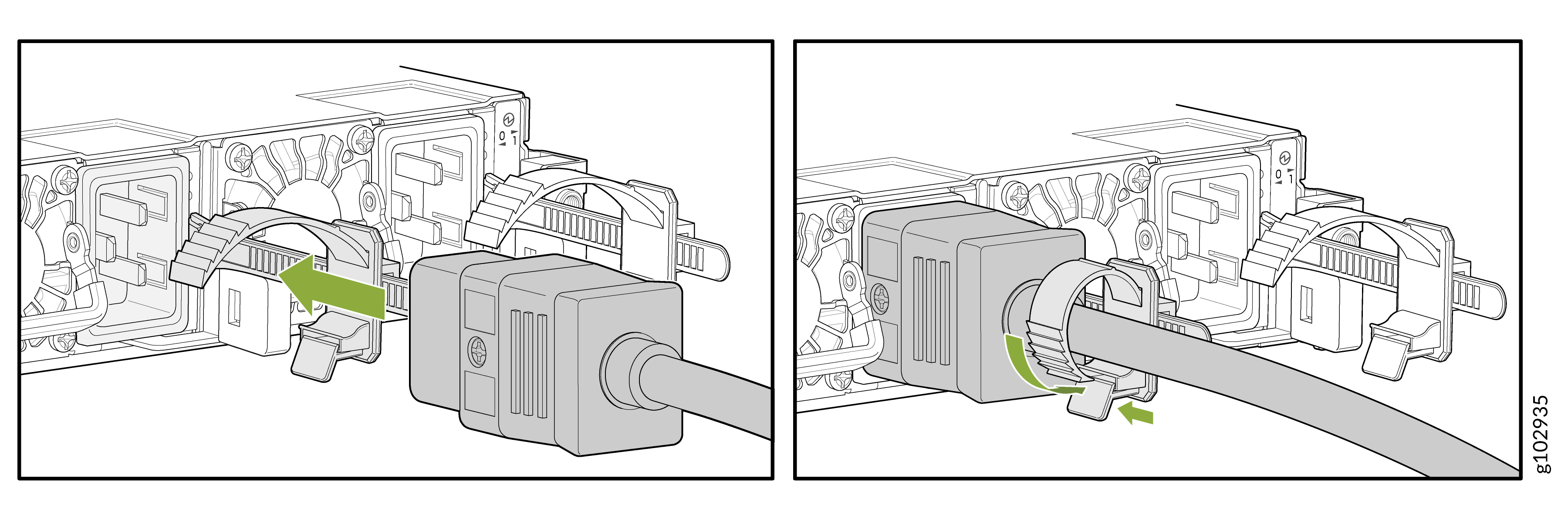
Push the retainer clip through the loop and tighten it until it fits snug
around the power cord.
Connect DC Power to the SRX4700
The DC power supply units (PSUs) in an SRX4700 are hot-removable and hot-insertable field-replaceable units (FRUs). You can remove and replace the DC PSUs without powering off the firewall or disrupting its functions.
You must not mix AC and DC PSUs in the same chassis.
Before you begin to connect DC power to the firewall:
-
Ensure that you have connected the chassis to an earth ground.
-
Ensure that you have the DC power cables and lugs to connect DC power to the firewall.
-
Ensure that you have taken the necessary precautions to prevent electrostatic discharge (ESD) damage.
-
Ensure that you have an ESD grounding strap.
-
If not already installed, install the power supplies in the firewall.
You connect DC power to the firewall by attaching power cables from the external DC power sources to the terminal studs on the power supply faceplates. You must provide the power cables and cable lugs (not supplied with the firewall). For power cable specifications, see DC Power Cable Specifications.
Before you connect power to the firewall, a licensed electrician must attach appropriate cable terminals to the grounding and power cables that you use. A cable with an incorrectly attached terminal can damage the firewall (for example, by causing a short circuit).
To meet safety and electromagnetic interference (EMI) requirements and to ensure proper operation, you must properly ground the chassis before connecting power. See Connect Earth Ground to the SRX4700 for instructions.
Before performing the following procedure, ensure that you remove the power from the DC circuit. To ensure that all power is off, locate the circuit breaker on the panel board that services the DC circuit. Switch the circuit breaker to the OFF position (0), and tape the switch handle of the circuit breaker in the OFF position.
To connect the DC source power cables to the firewall for each PSU:
-
Install heat-shrink tubing insulation around the power cables:
-
Slide the tubing over the portion of the cable where it is attached to the terminal barrel. Ensure that the tubing covers the end of the wire and the barrel of the terminal attached to it.
-
Shrink the tubing with a heat gun. Ensure that you heat all sides of the tubing evenly so that it shrinks around the cable tightly.
Note:Make sure that you do not overheat the tubing.
Figure 1: Install Heat-Shrink Tubing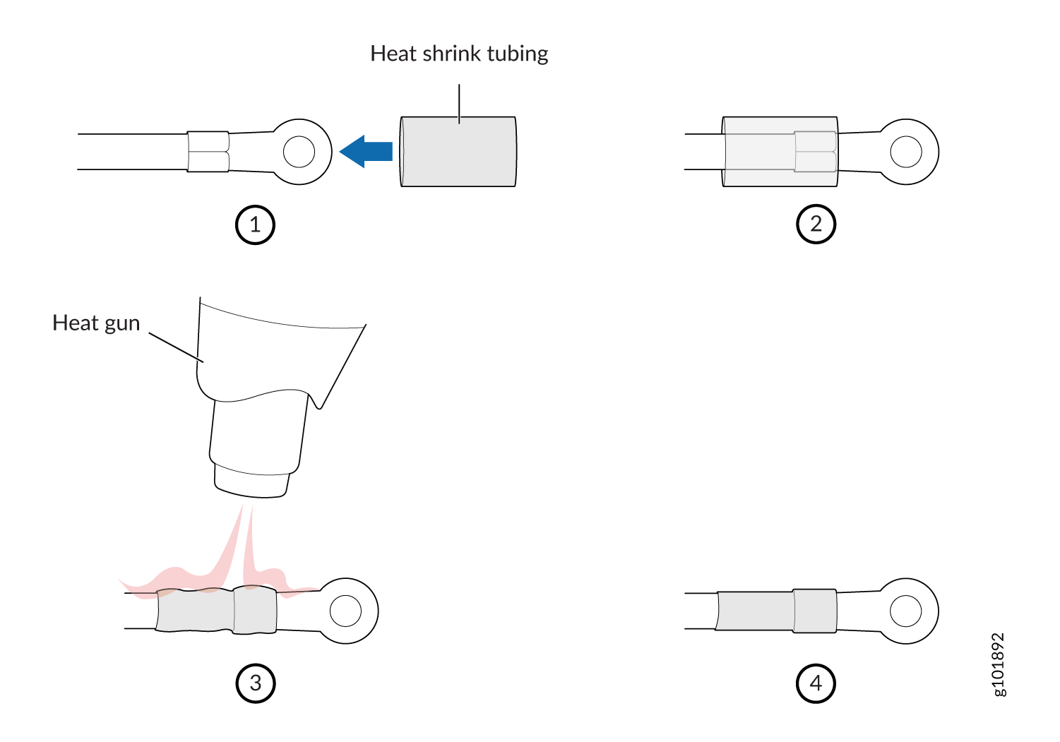
-
-
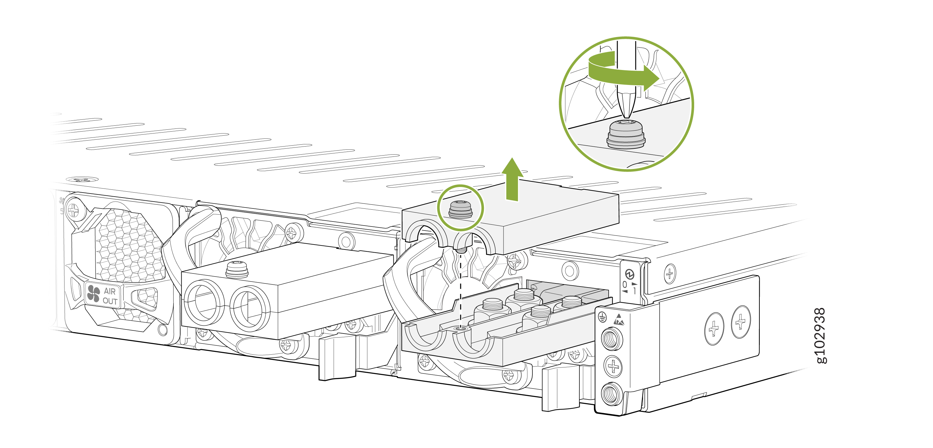
Using a screwdriver (anticlockwise), unscrew the nut on top of the terminal
block.
-
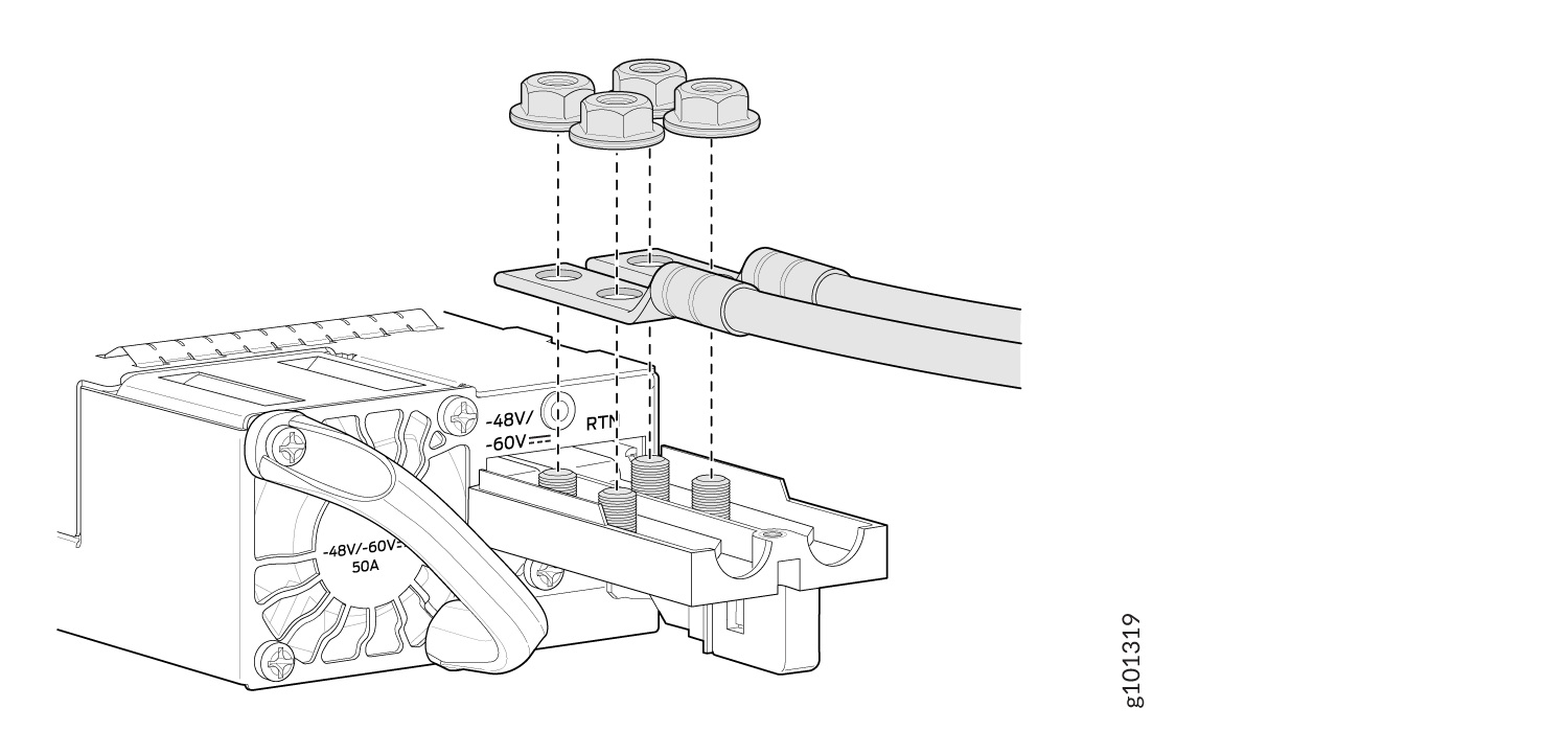
Secure each power cable lug to the terminals with the nuts. Tighten the
nuts on the power supply terminals until snug by using the screwdriver.
Apply between 23 lbf-in. (2.6 Nm) to and 25 lbf-in. (2.8 Nm) of torque to
the nuts. Do not apply vertical force while tightening the screws. Do not
overtighten the nuts. (Use a socket nutdriver.)
-
Secure the positive (+) DC source power cable lug to the RTN (return) terminal.
-
Secure the negative (—) DC source power cable lug to the —48 V/—60 V (input) terminal.
CAUTION:Ensure that each power cable lug seats flush against the surface of the terminal block as you are tightening the nuts. Ensure that each nut is properly threaded into the terminal. Applying installation torque to the nuts when improperly threaded can result in damage to the terminal.
CAUTION:You must ensure that power connections maintain the proper polarity. The power source cables might be labeled (+) and (–) to indicate their polarity. There is no standard color coding for DC power cables. The color coding used by the external DC power source at your site determines the color coding for the leads on the power cables that attach to the terminal studs on each power supply.
-
-
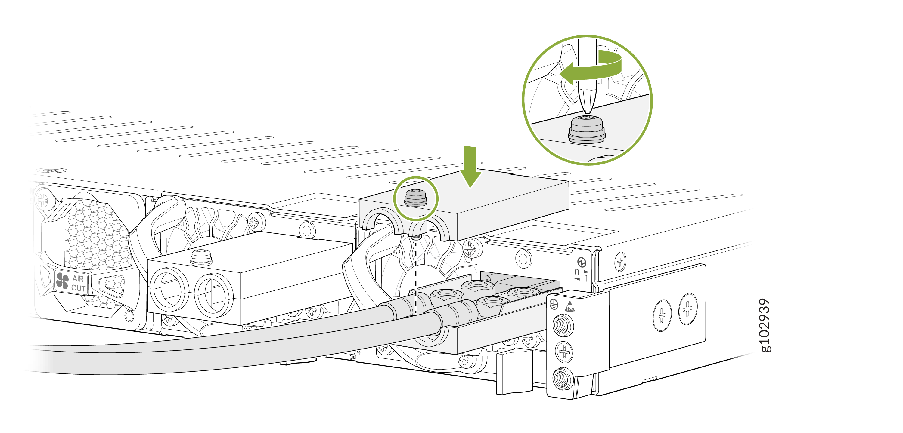
Place the terminal block cover on and tighten the screw.
Power Off the SRX4700
For a graceful shutdown, press and hold the power button for atleast 4 seconds. The firewall begins gracefully shutting down the operating system (OS) and then powers itself off.
Use the graceful shutdown method to power off or reboot the firewall.
To remove power completely from the firewall, unplug the AC power cord or DC power supply cable.
After powering off the device, wait at least 60 seconds before turning it back on. After powering on the device, wait at least 10 seconds before turning it off.
When the system is completely powered off and you turn on the power supply, the
firewall starts as the PSU completes its startup sequence. If the firewall
finishes starting and you need to power off the device again, first issue the
request vmhost halt command.
The fans in the PSU continue to rotate even after you power off the SRX4700 Firewall. To stop the fans, remove the power cord from the PSU. The fans will stop in a few seconds.
After turning on the power supply, it can take up to 60 seconds for status
indicators—such as the PWR LED and the show
chassis command display—to indicate that the power supply is
functioning normally. Ignore error indicators that appear during the first
60 seconds.