SSR1400 Fan Maintenance
Maintaining the SSR1400 includes removing and installing the fans.
The SSR1400 has four independent, field-replaceable fans (part number: JNP-FAN-SSRHE) installed on the rear of the chassis.
Each fan is a hot-removable and hot-insertable field-replaceable unit (FRU), which means that you can remove and replace the fans while the appliance is running. You can remove and replace the fans without turning off power to the appliance or disrupting its functions.
Ensure that you have the following parts and tools available:
-
Electrostatic discharge (ESD) grounding strap
-
Replacement fan
-
A Phillips (+) screwdriver, number 1 or 2 (optional), for the captive screw
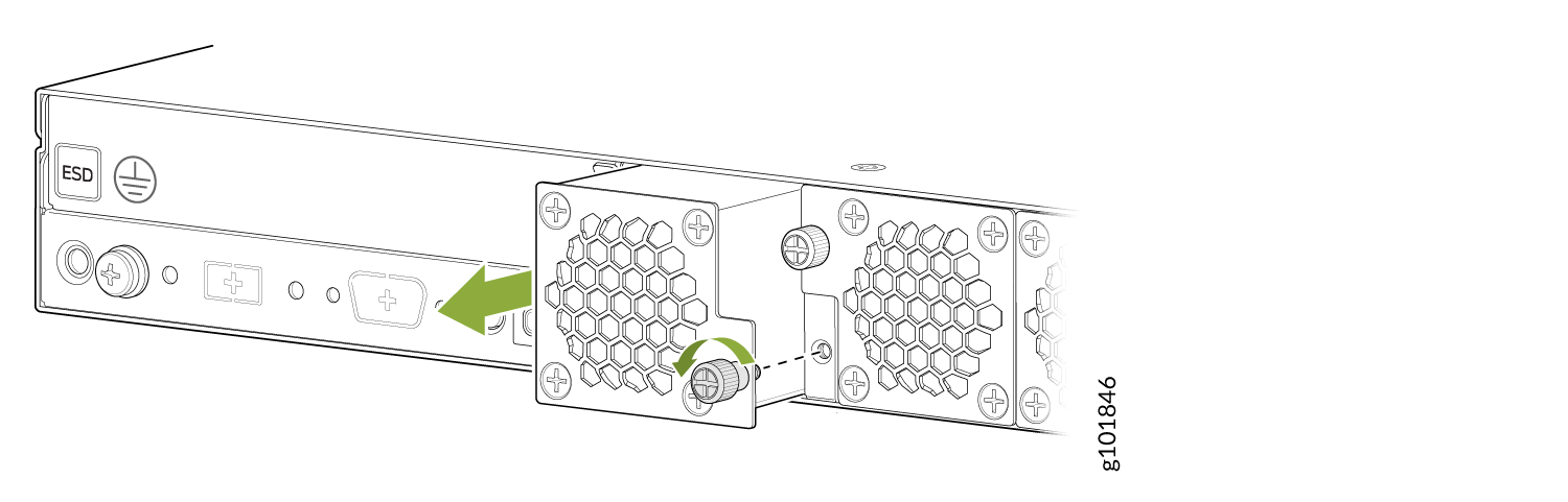
Remove a Fan from the SSR1400
Do not remove a fan unless you have a replacement fan available.
To remove an SSR1400 fan:
-
Grasp the captive screw and pull the fan completely out of the chassis. See
Figure 1.
Figure 1: Remove an SSR1400 Fan
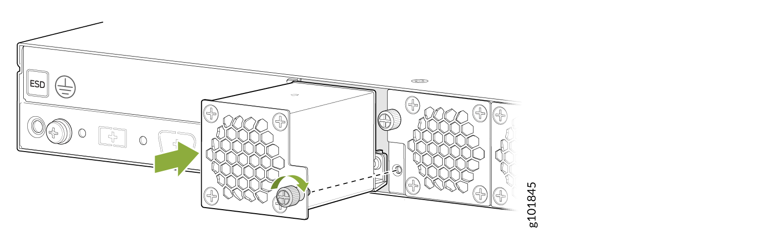
Install a Fan in the SSR1400
To install an SSR1400 fan:
- Wrap and fasten one end of the ESD grounding strap around your bare wrist, and connect the other end of the strap to one of the ESD points on the chassis.
- Align the bottom of the fan with the bottom of the fan slot.
- Rest the bottom edge of the fan in the slot and slide the fan into place so it is fully seated.
- Tighten the captive screw until it is finger tight. See Figure 2.