SSR1400 Power Supply Maintenance
Maintaining an SSR1400 appliance includes replacing power supplies. Replacing includes removing a failed power supply and installing a functional power supply.
Replacing an AC Power Supply on the SSR1400
The two AC power supplies (part number: JNP-650W-AC-SSRHE) are hot-removable and hot-insertable field-replaceable units (FRUs) installed in the rear panel of the SSR1400 appliance. You can remove and replace them without powering off the SSR1400 or disrupting the SSR1400 functions.
Ensure that you have the following parts and tools available:
-
ESD grounding strap
-
Antistatic bag or an antistatic mat
-
Replacement AC power supply
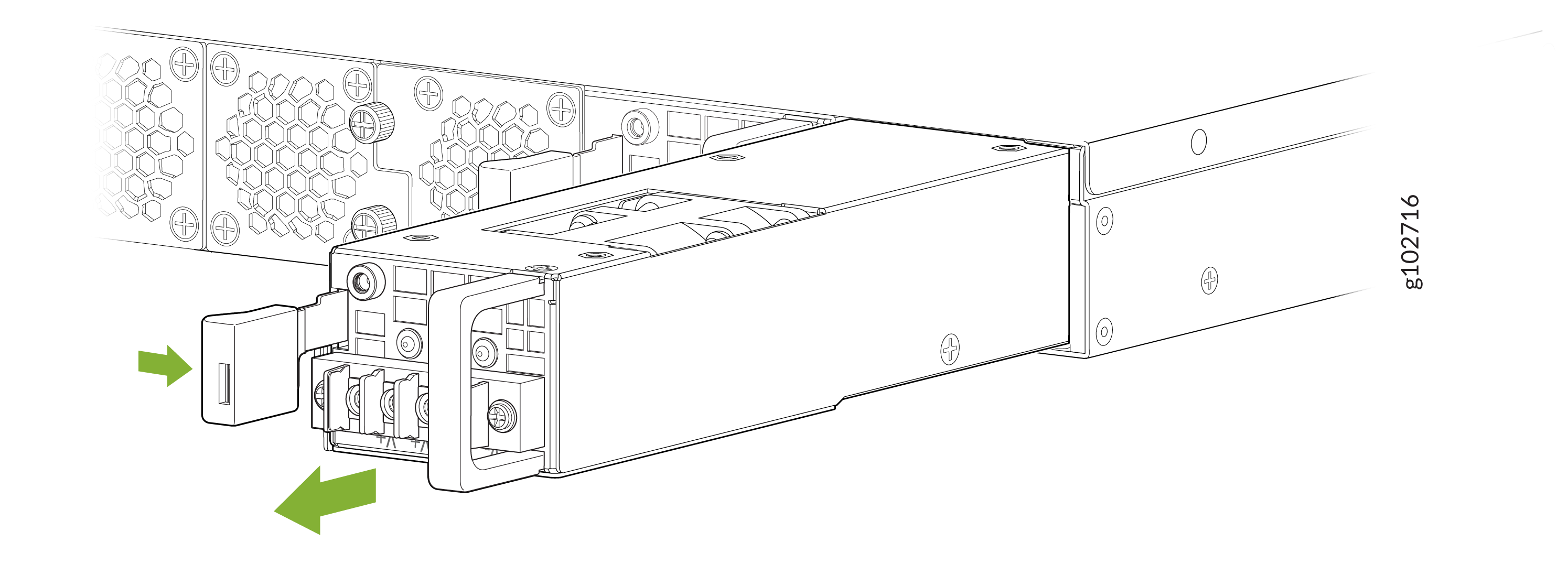
Removing the AC Power Supply from an SSR1400
To remove a power supply from the appliance (see Figure 1):
-
Place one hand under the power supply to support it and slide it
completely out of the chassis. Take care not to touch power supply
components, pins, leads, or solder connections.
Figure 1: Remove an SSR1400 AC Power Supply
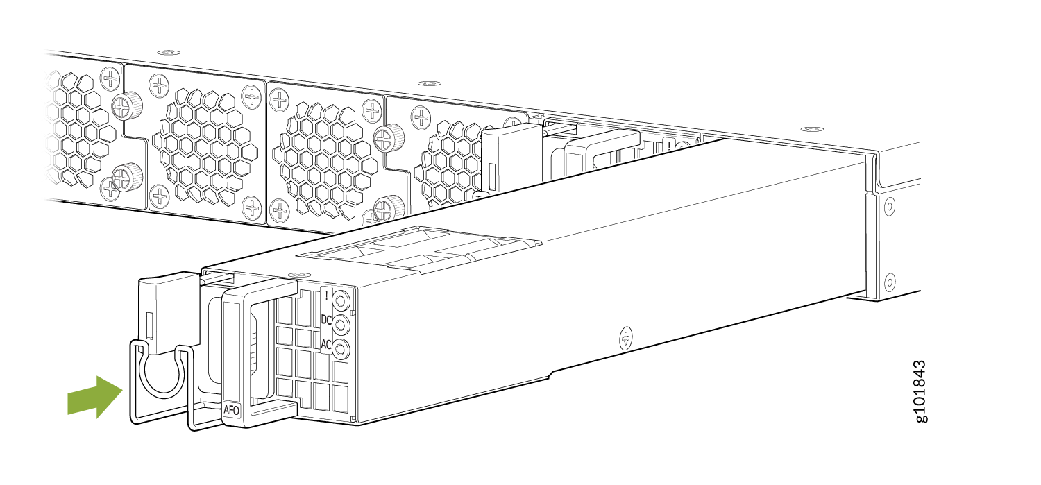
Installing the AC Power Supply in an SSR1400
To install an AC power supply (see Figure 2):
-
Using both hands, place the power supply in the power supply slot on
the rear panel of SSR1400 and slide it in until it is fully seated and
the ejector lever fits into place. You will hear a distinct click when
the power supply is fully seated in the chassis.
Figure 2: Install an SSR1400 AC Power Supply
Replacing a DC Power Supply on the SSR1400-DC
The two DC power supplies (part number: JPSU-650W-DC-F-AFO) are field-replaceable units (FRUs) installed in the rear panel of the SSR1400-DC appliance. However, due to the DC power requirements the entire unit must be taken off line and powered down.
Do not attempt to install a DC power supply into an SSR1400 that originally contained an AC power supply. This may result in damage to the SSR1400, and the appliance may not function.
In most cases, electrical code requires that DC connection be performed by a licensed professional. Please consult your local electrical codes before replacing a DC power supply.
Ensure that you have the following parts and tools available:
-
ESD grounding strap
-
Antistatic bag or an antistatic mat
-
Replacement DC power supply
-
#2 Phillips Screwdriver
There are three tasks to replace the DC power supply:
-
Disconnect Power
-
Remove the existing DC power supply
-
Install the new DC power supply
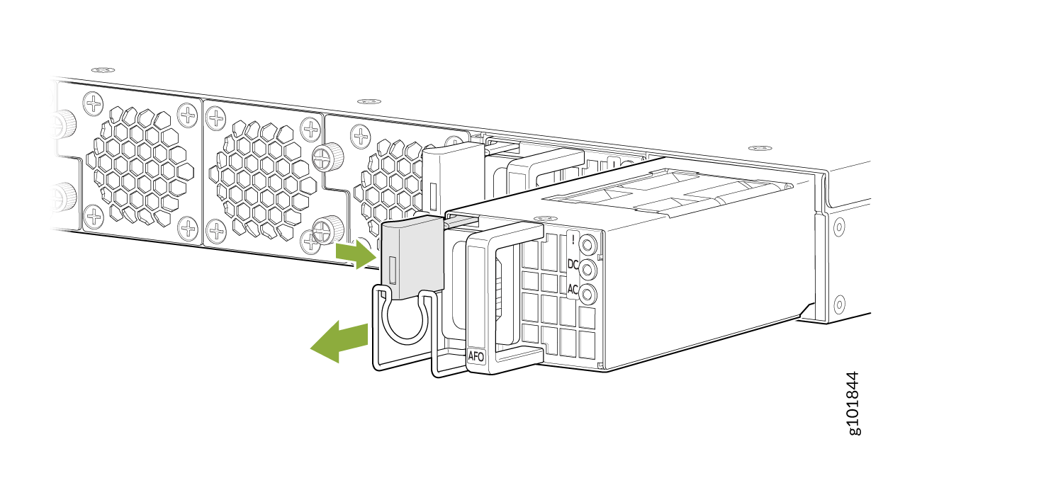
Removing a DC Power Supply from the SSR1400-DC
Up to two power supplies can be located at the rear of the chassis on the right side. Each DC power supply weighs approximately 2.20 lbs (1 kg).
Do not leave a power supply slot empty for more than 30 minutes while the SSR is operational. For proper airflow, the power supply must remain in the chassis, or a blank panel must be used in the empty slot.
After powering off a power supply, wait at least 60 seconds before turning it back on.
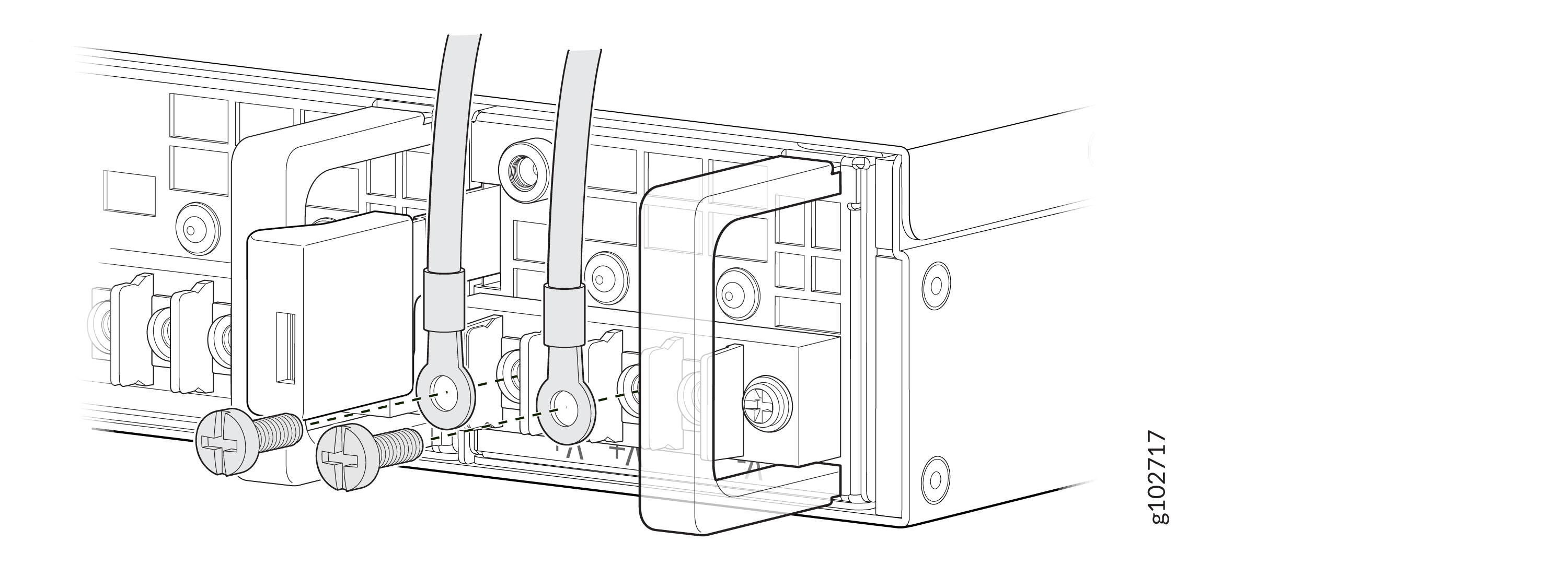
Wire the DC power supply using the appropriate lugs. When disconnecting power, the proper wiring sequence is:
Negative (–) DC source power cable lug to a -48V (input) terminal
Positive (+) DC source power cable lug to a (+) RTN (return) terminal.
Ground to Ground
Note that the ground wire should always be connected first and disconnected last.
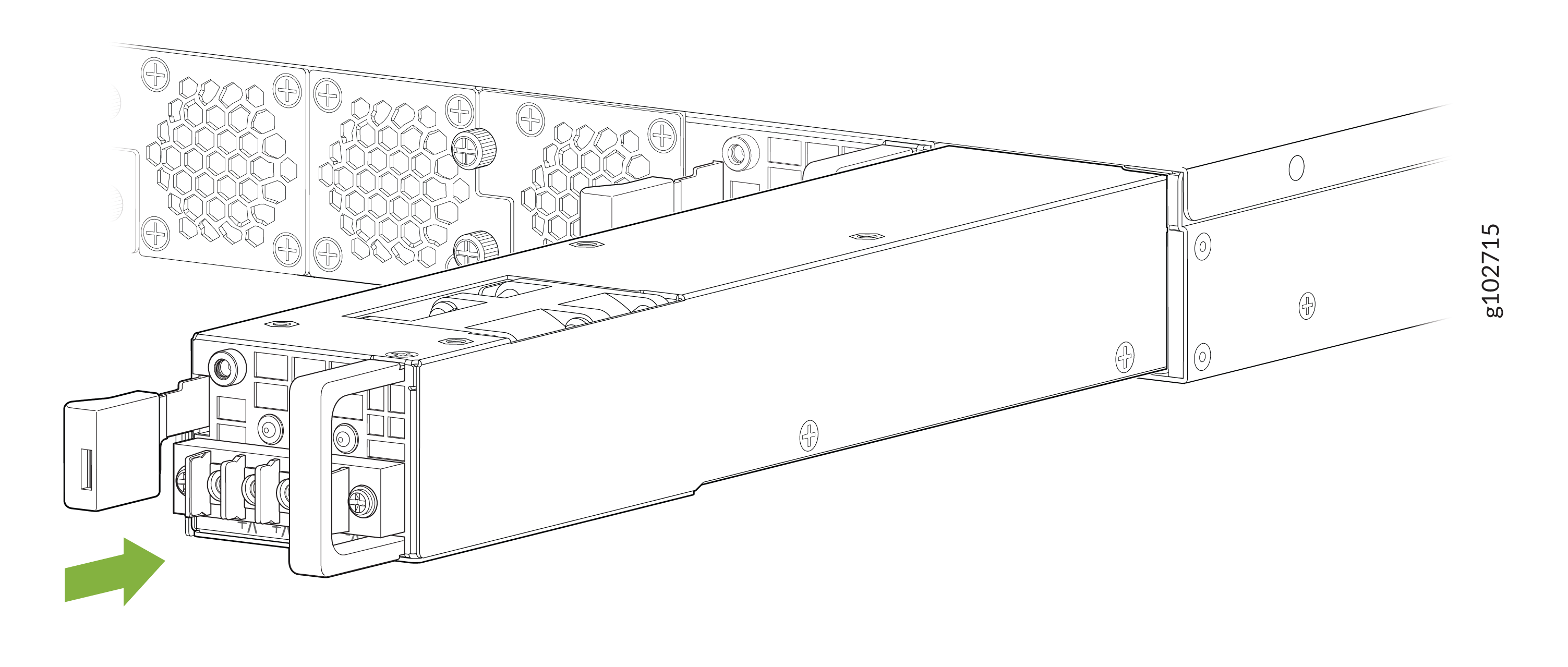
To remove a DC power supply:
-
Remove the screws and washers from the terminals using a number 2
Phillips screwdriver.
Figure 3: Remove Terminal Screws
Installing a DC Power Supply in the SSR1400-DC
Wire the DC power supply using the appropriate lugs. When connecting power, the proper wiring sequence is:
Ground to Ground
Positive (+) DC source power cable lug to a (+) RTN (return) terminal.
Negative (–) DC source power cable lug to a -48V (input) terminal
Note that the ground wire should always be connected first and disconnected last.
Use the following steps to install a DC power supply:
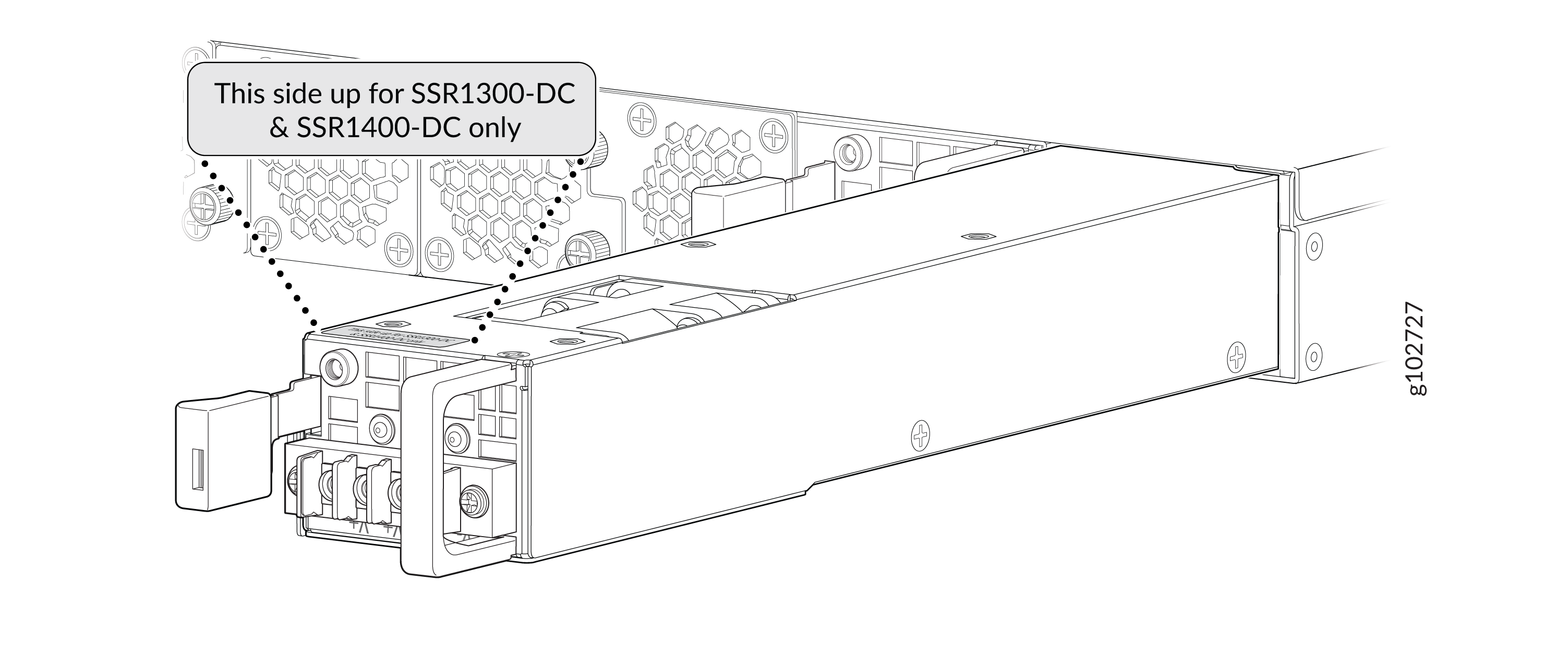
When installing a DC power supply in either an SSR1300-DC or an SSR1400-DC, the label indicating proper install orientation MUST be facing up, the orange handle must be on the RIGHT, and the locking lever must be on the LEFT as shown in the diagram below. If it is not installed in this orientation, it will not make proper electrical connection and could electrify the chassis.
-
Orient the power supply so that the orange handle is on the RIGHT, and
the locking lever is on the LEFT as shown in the diagram below. If the
power supply is installed incorrectly, it will not make proper
electrical connection and and could electrify the chassis.
Figure 6: Insert the DC Power Supply
-
Secure each power cable lug to the terminal studs, first with the
square washer, then with the screw. Apply between 23 lb-in. (2.6 Nm) and
25 lb-in. (2.8 Nm) of torque to each screw.
- Attach the positive (+) DC source power cable lug to the RTN (return) terminal.
- Attach the negative (–) DC source power cable lug to the –48V (input) terminal.
Note:The text on the power supply describing each terminal is upside down. This is correct for the orientation of the power supply.
Figure 7: Securing the Power Cables
If more than one power supply is being installed, turn on both power supplies at the same time.
If both power supplies are plugged in and receiving power, the RPS LED glows solid green.