ON THIS PAGE
Example: Configure Full Mesh Chassis Cluster
This example shows how to set up basic active/passive full mesh chassis clustering on a pair of SRX5000 line of Firewalls.
Requirements
This example uses the following hardware and software components:
-
Two SRX5800 Firewalls with identical hardware configurations running same Junos OS version. Release 18.1R1.
-
Two MX480 3D Universal Edge Routers running Junos OS Release 18.1R1.
-
Two EX9214 Ethernet Switches running Junos OS Release 18.1R1.
This configuration example has been tested using the software release listed and is assumed to work on all later releases.
Before you begin:
-
Physically connect the two SRX5800 Firewalls (back-to-back for the fabric and control ports).
Overview
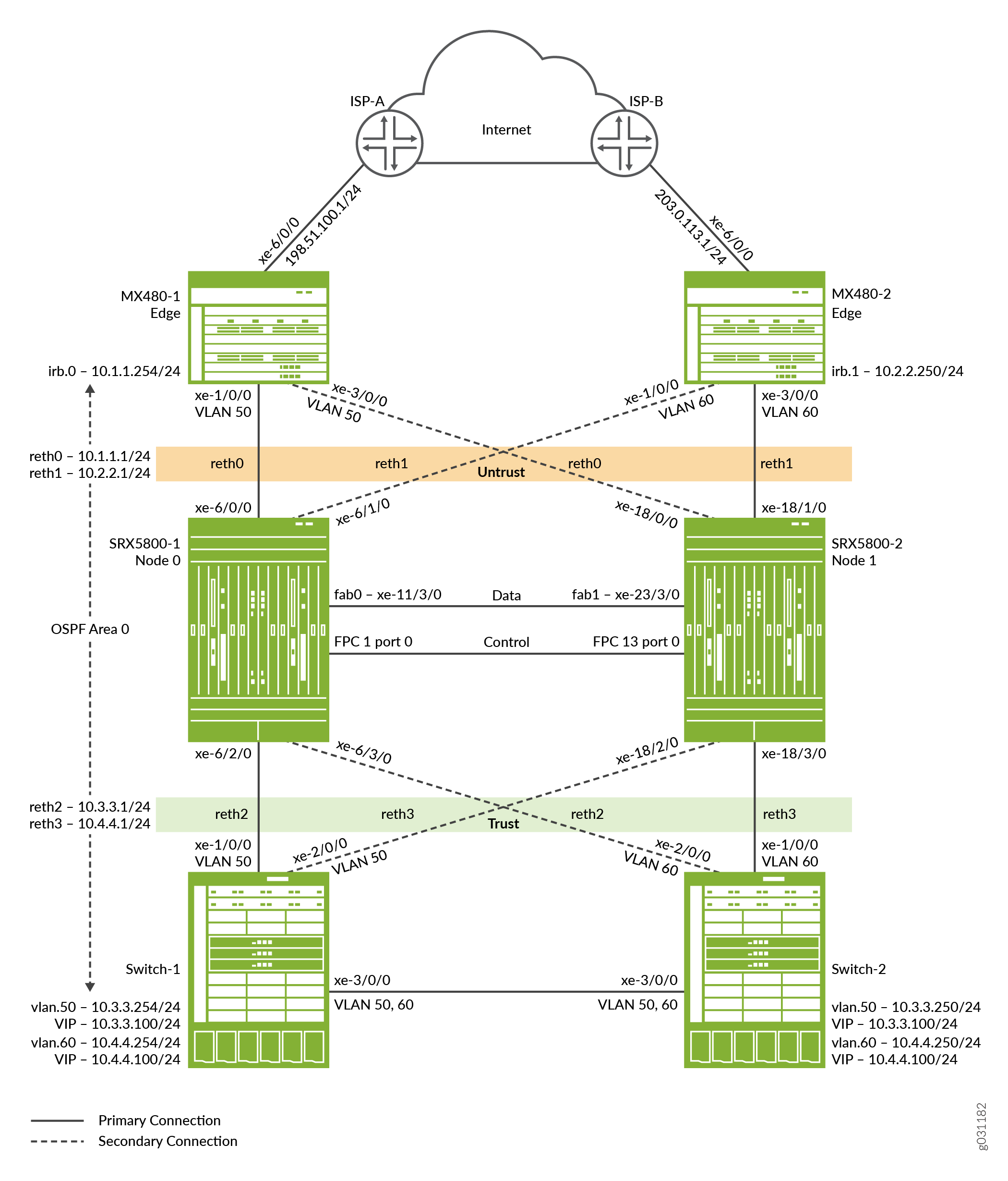
This example shows how to set up basic active/passive full mesh chassis clustering. Full mesh active/passive clustering allows you to set up an environment that does not have a single point of failure on all the network devices. The main difference in the full mesh deployment described in this example and the basic active/passive deployment described in Configuring an Active/Passive Chassis Cluster Deployment is that additional design elements must be considered to accommodate recovery of possible failure scenarios.
Full mesh chassis clustering requires you to configure reth interfaces for each node and ensure that they are connected together by one or more switches. In this scenario, shown in Figure 1, there are four reth interfaces (reth0, reth1, reth2, and reth3). A reth interface bundles the two physical interfaces (one from each node) together. A reth interface is part of a redundancy group. Only the member that is on the primary node (active) for the redundancy group is active. The member on the secondary (passive) node is completely inactive, that is, it does not send or receive any traffic.
Each reth interface can have one or more logical or subinterfaces (for example, reth 0.0, reth 0.1, and so forth). Each must use a different VLAN tag.
The full mesh active/passive chassis cluster consists of two devices:
-
One device actively provides routing, firewall, NAT, VPN, and security services, along with maintaining control of the chassis cluster.
-
The other device passively maintains its state for cluster failover capabilities should the active device become inactive.
Figure 1 shows the topology used in this example.
Configuration
To configure this example, perform the following procedures:
- Configure the Control Ports
- Enabling Cluster Mode
- Configuring Cluster Mode
- Configuring Zones, Security Policy, and Protocols
- Configure EX9214-1
- Configure EX9214-2
- Configure MX480-1
- Configure MX480-2
- Configure Miscellaneous Settings
Configure the Control Ports
Step-by-Step Procedure
Select FPC 1/13, because the central point (CP) is always on the lowest SPC/SPU in the cluster (for this example, it is slot 0). For maximum reliability, place the control ports on a separate SPC from the central point (for this example, use the SPC in slot 1). You must enter the operational mode commands on both devices.
Control port configuration is required for SRX5600 Firewall and SRX5800 Firewall.
To configure the control port for each device, and commit the configuration:
-
Configure the control port for the SRX5800-1 (node 0) and commit the configuration.
user@host# set chassis cluster control-ports fpc 1 port 0
user@host# set chassis cluster control-ports fpc 13 port 0
user@host# commit and-quit
-
Configure the control port for the SRX5800-2 (node 1) and commit the configuration.
user@host# set chassis cluster control-ports fpc 1 port 0
user@host# set chassis cluster control-ports fpc 13 port 0
user@host# commit and-quit
Enabling Cluster Mode
Step-by-Step Procedure
Set the two devices to cluster mode. A reboot is required to enter into
cluster mode after the cluster ID and node ID are set. You can cause the
system to boot automatically by including the reboot
parameter in the CLI. You must enter the operational mode commands on both
devices. When the system boots, both the nodes come up as a cluster.
Since there is only a single cluster on the segments, this example uses cluster ID 1 with Device SRX5800-1 as node 0 and Device SRX5800-2 as node 1.
To set the two devices in cluster mode:
-
Enable cluster mode on the SRX5800-1 (node 0).
user@host> set chassis cluster cluster-id 1 node 0 reboot
-
Enable cluster mode on the SRX5800-2 (node 1).
user@host> set chassis cluster cluster-id 1 node 1 reboot
Note:If you have multiple clusters on a single broadcast domain, ensure that you assign different cluster IDs to each cluster to avoid a MAC address conflict.
The cluster ID is the same on both devices, but the node ID must be different because one device is node 0 and the other device is node 1. The range for the cluster ID is 1 through 15. Setting a cluster ID to 0 is equivalent to disabling a cluster.
Now the devices are a pair. From this point forward, configuration of the cluster is synchronized between the node members, and the two separate devices function as one device.
Configuring Cluster Mode
Step-by-Step Procedure
In cluster mode, the cluster is synchronized between the nodes when you
execute a commit command. All commands are applied to
both nodes regardless of which device the command is configured on.
To configure a chassis cluster:
-
Configure the fabric (data) ports of the cluster that are used to pass real-time objects (RTOs) in active/passive mode. Define two fabric interfaces, one on each chassis, to connect together.
user@host# set interfaces fab0 fabric-options member-interfaces xe-11/3/0
user@host# set interfaces fab1 fabric-options member-interfaces xe-23/3/0
-
Since the chassis cluster uses a single common configuration, apply the Junos OS node-specific configuration method called groups method to assign certain elements to specific members only.
The
set apply-groups ${node}command uses the node variable to define how the groups are applied to the nodes. Each node recognizes its number and accepts the configuration accordingly. You must also configure out-of-band management on the fxp0 interface of the SRX5800 Firewall using separate IP addresses for the individual control planes of the cluster.Note:Configuring the backup router destination address as x.x.x.0/0 is not allowed.
user@host# set groups node0 system host-name SRX5800-1 user@host# set groups node0 system backup-router 10.52.63.254 user@host# set groups node0 system backup-router destination 10.0.0.0/8 user@host# set groups node0 interfaces fxp0 unit 0 family inet address 10.52.43.57/19 user@host# set groups node1 system host-name SRX5800-2 user@host# set groups node1 system backup-router 10.52.63.254 user@host# set groups node1 system backup-router destination 10.0.0.0/8 user@host# set groups node1 interfaces fxp0 unit 0 family inet address 10.52.52.27/19 user@host# set apply-groups “${node}” -
Configure redundancy groups for chassis clustering. Each node has interfaces in a redundancy group where interfaces are active in active redundancy groups (multiple active interfaces can exist in one redundancy group).
Redundancy group 0 controls the control plane and redundancy group 1+ controls the data plane and includes the data plane ports. For any active/passive mode cluster, only redundancy groups 0 and 1 need to be configured. Use four reth interfaces, all of which are members of redundancy group 1. Besides redundancy groups, you must also define:
-
Redundant Ethernet Interface count—Configure how many redundant Ethernet interfaces (reth) can possibly be configured so that the system can allocate the appropriate resources for it.
-
Priority for control plane and data plane—Define which device has priority (for chassis cluster, high priority is preferred) for the control plane, and which device is preferred to be active for the data plane.
Note:In active/passive or active/active mode, the control plane (redundancy group 0) can be active on a chassis different from the data plane (redundancy group 1+ and groups) chassis. However, for this example, we recommend having both the control and data plane active on the same chassis member. When traffic passes through the fabric link to go to another member node, latency is introduced.
user@host# set chassis cluster reth-count 4
user@host# set chassis cluster redundancy-group 0 node 0 priority 129
user@host# set chassis cluster redundancy-group 0 node 1 priority 128
user@host# set chassis cluster redundancy-group 1 node 0 priority 129
user@host# set chassis cluster redundancy-group 1 node 1 priority 128
-
-
Configure the data interfaces on the platform so that in the event of a data plane failover, the other chassis cluster member can take over the connection seamlessly.
Seamless transition to a new active node occurs with data plane failover. In case of control plane failover, all the daemons are restarted on the new node. Because of this, enabling graceful restart for relevant routing protocols is strongly recommended to avoid losing neighborships with peers. This promotes a seamless transition to the new node without any packet loss.
Define the following items:
-
Membership information of the member interfaces to the reth interface.
user@host# set interfaces xe-6/0/0 gigether-options redundant-parent reth0
user@host# set interfaces xe-6/1/0 gigether-options redundant-parent reth1
user@host# set interfaces xe-6/2/0 gigether-options redundant-parent reth2
user@host# set interfaces xe-6/3/0 gigether-options redundant-parent reth3
user@host# set interfaces xe-18/0/0 gigether-options redundant-parent reth0
user@host# set interfaces xe-18/1/0 gigether-options redundant-parent reth1
user@host# set interfaces xe-18/2/0 gigether-options redundant-parent reth2
user@host# set interfaces xe-18/3/0 gigether-options redundant-parent reth3
-
Which redundancy group the reth interface is a member of. For this active/passive example, it is always 1.
user@host# set interfaces reth0 redundant-ether-options redundancy-group 1
user@host# set interfaces reth1 redundant-ether-options redundancy-group 1
user@host# set interfaces reth2 redundant-ether-options redundancy-group 1
user@host# set interfaces reth3 redundant-ether-options redundancy-group 1
-
The reth interface information such as the IP address of the interface.
user@host# set interfaces reth0 unit 0 family inet address 10.1.1.1/24
user@host# set interfaces reth1 unit 0 family inet address 10.2.2.1/24
user@host# set interfaces reth2 unit 0 family inet address 10.3.3.1/24
user@host# set interfaces reth3 unit 0 family inet address 10.4.4.1/24
-
-
Configure the chassis cluster behavior in case of a failure.
Each interface is configured with a weight value that is deducted from the redundancy group threshold of 255 upon a link loss. The failover threshold is hard coded at 255 and cannot be changed. You can alter an interface link’s weight to determine the impact on the chassis failover.
When a redundancy group threshold reaches 0, that redundancy group fails over to the secondary node.
Enter the following commands on the SRX5800-1:
user@host# set chassis cluster redundancy-group 1 interface-monitor xe-6/0/0 weight 255
user@host# set chassis cluster redundancy-group 1 interface-monitor xe-6/1/0 weight 255
user@host# set chassis cluster redundancy-group 1 interface-monitor xe-6/2/0 weight 255
user@host# set chassis cluster redundancy-group 1 interface-monitor xe-6/3/0 weight 255
user@host# set chassis cluster redundancy-group 1 interface-monitor xe-18/0/0 weight 255
user@host# set chassis cluster redundancy-group 1 interface-monitor xe-18/1/0 weight 255
user@host# set chassis cluster redundancy-group 1 interface-monitor xe-18/2/0 weight 255
user@host# set chassis cluster redundancy-group 1 interface-monitor xe-18/3/0 weight 255
user@host# set chassis cluster control-link-recovery
user@host# set chassis cluster redundancy-group 1 preempt
This step completes the chassis cluster configuration part of the active/passive mode example for the SRX5800 Firewall. The rest of this procedure describes how to configure the zone, virtual router, routing, and the MX480 to complete the deployment scenario.
Configuring Zones, Security Policy, and Protocols
Step-by-Step Procedure
Configure zones and add the appropriate reth interfaces, and configure OSPF.
To configure zones and OSPF:
-
Configure two zones and add the appropriate reth interfaces .
user@host# set security zones security-zone Untrust interfaces reth0.0
user@host# set security zones security-zone Untrust interfaces reth1.0
user@host# set security zones security-zone Trust interfaces reth2.0
user@host# set security zones security-zone Trust interfaces reth3.0
-
Permit the appropriate protocols and services to reach interfaces in the Trust and Untrust zones.
user@host# set security zones security-zone Trust host-inbound-traffic protocols ospf
user@host# set security zones security-zone Trust host-inbound-traffic system-services all
user@host# set security zones security-zone Untrust host-inbound-traffic system-services ping
user@host# set security zones security-zone Untrust host-inbound-traffic protocols ospf
-
Configure a security policy to permit traffic from the trust zone to the untrust zone.
user@host# set security policies from-zone Trust to-zone Untrust policy allow match source-address any
user@host# set security policies from-zone Trust to-zone Untrust policy allow match destination-address any
user@host# set security policies from-zone Trust to-zone Untrust policy allow match application any
user@host# set security policies from-zone Trust to-zone Untrust policy allow then permit
user@host# set security policies from-zone Untrust to-zone Trust policy allow match source-address any
user@host# set security policies from-zone Untrust to-zone Trust policy allow match destination-address any
user@host# set security policies from-zone Untrust to-zone Trust policy allow match application any
user@host# set security policies from-zone Untrust to-zone Trust policy allow then permit
-
Configure OSPF.
user@host# set protocols ospf area 0.0.0.0 interface reth0.0
user@host# set protocols ospf area 0.0.0.0 interface reth1.0
user@host# set protocols ospf area 0.0.0.0 interface reth2.0
user@host# set protocols ospf area 0.0.0.0 interface reth3.0
Configure EX9214-1
Step-by-Step Procedure
For the Ethernet switches, the following commands provide only an outline of the applicable configuration as it pertains to this active/passive full mesh example for the SRX5800 Firewall; most notably the VLANs, routing, and interface configuration.
To configure the EX9214-1:
-
Configure the interfaces.
user@host# set interfaces xe-1/0/0 unit 0 family ethernet-switching interface-mode access
user@host# set interfaces xe-1/0/0 unit 0 family ethernet-switching vlan members SRX5800-RETH2
user@host# set interfaces xe-2/0/0 unit 0 family ethernet-switching interface-mode access
user@host# set interfaces xe-2/0/0 unit 0 family ethernet-switching vlan members SRX5800-RETH2
user@host# set interfaces xe-3/0/0 unit 0 family ethernet-switching interface-mode trunk
user@host# set interfaces xe-3/0/0 unit 0 family ethernet-switching vlan members SRX5800-RETH2
user@host# set interfaces xe-3/0/0 unit 0 family ethernet-switching vlan members SRX5800-RETH3
-
Configure VRRP between the two EX switches.
user@host# set interfaces irb unit 50 family inet address 10.3.3.254/24 vrrp-group 1 virtual-address 10.3.3.100
user@host# set interfaces irb unit 50 family inet address 10.3.3.254/24 vrrp-group 1 priority 200
user@host# set interfaces irb unit 50 family inet address 10.3.3.254/24 vrrp-group 1 accept-data
user@host# set interfaces irb unit 60 family inet address 10.4.4.254/24 vrrp-group 2 virtual-address 10.4.4.100
user@host# set interfaces irb unit 60 family inet address 10.4.4.254/24 vrrp-group 2 priority 100
user@host# set interfaces irb unit 60 family inet address 10.4.4.254/24 vrrp-group 2 accept-data
-
Configure the VLANs.
user@host# set vlans SRX5800-RETH2 vlan-id 50
user@host# set vlans SRX5800-RETH2 l3-interface irb.50
user@host# set vlans SRX5800-RETH3 vlan-id 60
user@host# set vlans SRX5800-RETH3 l3-interface irb.60
-
Configure the protocols.
user@host# set protocols ospf area 0.0.0.0 interface irb.50
user@host# set protocols ospf area 0.0.0.0 interface irb.60
user@host# set protocols rstp interface all
Configure EX9214-2
Step-by-Step Procedure
To configure the EX9214-2:
-
Configure the interfaces.
user@host# set interfaces xe-1/0/0 unit 0 family ethernet-switching interface-mode access
user@host# set interfaces xe-1/0/0 unit 0 family ethernet-switching vlan members SRX5800-RETH3
user@host# set interfaces xe-2/0/0 unit 0 family ethernet-switching interface-mode access
user@host# set interfaces xe-2/0/0 unit 0 family ethernet-switching vlan members SRX5800-RETH3
user@host# set interfaces xe-3/0/0 unit 0 family ethernet-switching interface-mode trunk
user@host# set interfaces xe-3/0/0 unit 0 family ethernet-switching vlan members SRX5800-RETH2
user@host# set interfaces xe-3/0/0 unit 0 family ethernet-switching vlan members SRX5800-RETH3
-
Configure VRRP between the two EX switches.
user@host# set interfaces irb unit 50 family inet address 10.3.3.250/24 vrrp-group 1 virtual-address 10.3.3.100
user@host# set interfaces irb unit 50 family inet address 10.3.3.250/24 vrrp-group 1 priority 100
user@host# set interfaces irb unit 50 family inet address 10.3.3.250/24 vrrp-group 1 accept-data
user@host# set interfaces irb unit 60 family inet address 10.4.4.250/24 vrrp-group 2 virtual-address 10.4.4.100
user@host# set interfaces irb unit 60 family inet address 10.4.4.250/24 vrrp-group 2 priority 200
user@host# set interfaces irb unit 60 family inet address 10.4.4.250/24 vrrp-group 2 accept-data
-
Configure the VLANs.
user@host# set vlans SRX5800-RETH2 vlan-id 50
user@host# set vlans SRX5800-RETH2 l3-interface irb.50
user@host# set vlans SRX5800-RETH3 vlan-id 60
user@host# set vlans SRX5800-RETH3 l3-interface irb.60
-
Configure the protocols.
user@host# set protocols ospf area 0.0.0.0 interface irb.50
user@host# set protocols ospf area 0.0.0.0 interface irb.60
user@host# set protocols rstp interface all
Configure MX480-1
Step-by-Step Procedure
For the MX480 Edge Routers, the following commands provide only an outline of the applicable configuration as it pertains to this active/passive mode example for the SRX5800 Services Gateway; most notably you must use an IRB interface within a virtual switch instance on the switch.
To configure the MX480-1:
-
Configure the downstream interfaces.
user@host# set interfaces xe-1/0/0 encapsulation ethernet-bridge
user@host# set interfaces xe-1/0/0 unit 0 family bridge
user@host# set interfaces xe-3/0/0 encapsulation ethernet-bridge
user@host# set interfaces xe-3/0/0 unit 0 family bridge
-
Configure the upstream interface.
user@host# set interfaces xe-6/0/0 unit 0 family inet address 198.51.100.1/24
-
Configure the IRB interface.
user@host# set interfaces irb unit 0 family inet address 10.1.1.254/24
-
Configure a static route and graceful restart.
user@host# set routing-options static route 0.0.0.0/0 next-hop 198.51.100.254
user@host# set policy-options policy-statement def-route term 1 from protocol static
user@host# set policy-options policy-statement def-route term 1 from route-filter 0.0.0.0/0 exact
user@host# set policy-options policy-statement def-route term 1 then accept
-
Configure the bridge domain.
user@host# set bridge-domains BD-50 vlan-id 50
user@host# set bridge-domains BD-50 domain-type bridge
user@host# set bridge-domains BD-50 interface xe-1/0/0
user@host# set bridge-domains BD-50 interface xe-3/0/0
user@host# set bridge-domains BD-50 routing-interface irb.0
-
Configure OSPF.
user@host# set protocols ospf area 0.0.0.0 interface irb.0
user@host# set protocols ospf area 0.0.0.0 interface xe-6/0/0.0 passive
user@host# set protocols ospf export def-route
Configure MX480-2
Step-by-Step Procedure
To configure the MX480-2:
-
Configure the downstream interfaces.
user@host# set interfaces xe-1/0/0 encapsulation ethernet-bridge
user@host# set interfaces xe-1/0/0 unit 0 family bridge
user@host# set interfaces xe-3/0/0 encapsulation ethernet-bridge
user@host# set interfaces xe-3/0/0 unit 0 family bridge
-
Configure the upstream interface.
user@host# set interfaces xe-6/0/0 unit 0 family inet address 203.0.113.1/24
-
Configure the IRB interface.
user@host# set interfaces irb unit 0 family inet address 10.2.2.250/24
-
Configure a static route and graceful restart.
user@host# set routing-options static route 0.0.0.0/0 next-hop 203.0.113.254
user@host# set policy-options policy-statement def-route term 1 from protocol static
user@host# set policy-options policy-statement def-route term 1 from route-filter 0.0.0.0/0 exact
user@host# set policy-options policy-statement def-route term 1 then accept
-
Configure the bridge domain.
user@host# set bridge-domains BD-60 vlan-id 60
user@host# set bridge-domains BD-60 domain-type bridge
user@host# set bridge-domains BD-60 interface xe-1/0/0
user@host# set bridge-domains BD-60 interface xe-3/0/0
user@host# set bridge-domains BD-60 routing-interface irb.0
-
Configure OSPF.
user@host# set protocols ospf area 0.0.0.0 interface irb.0
user@host# set protocols ospf area 0.0.0.0 interface xe-6/0/0.0 passive
user@host# set protocols ospf export def-route
Configure Miscellaneous Settings
Step-by-Step Procedure
This full mesh chassis clustering example for the SRX5800 Firewall does not describe in detail miscellaneous configurations such as how to configure NAT, security policies, or VPNs. They are essentially the same as they would be for standalone configurations.
However, if you are performing proxy ARP in chassis cluster configurations, you must apply the proxy ARP configurations to the reth interfaces rather than the member interfaces because the reth interfaces hold the logical configurations.
You can also configure separate logical interface configurations using VLANs and trunked interfaces in the SRX5800 Firewall. These configurations are similar to the standalone implementations using VLANs and trunked interfaces.
Verification
To confirm that the configuration is working properly, perform these tasks:
- Verify Chassis Cluster Status
- Verify Chassis Cluster Interfaces
- Verify Chassis Cluster Statistics
- Verify Chassis Cluster Control Plane Statistics
- Verifying Chassis Cluster Data Plane Statistics
- Verifying Chassis Cluster Redundancy Group Status
- Verify Connection on EX Device
- Troubleshoot with Logs
Verify Chassis Cluster Status
Purpose
Verify the chassis cluster status, failover status, and redundancy group information.
Action
From operational mode, enter the show chassis cluster
status command.
{primary:node0}
user@host> show chassis cluster status
Monitor Failure codes:
    CS  Cold Sync monitoring        FL  Fabric Connection monitoring
    GR  GRES monitoring             HW  Hardware monitoring
    IF  Interface monitoring        IP  IP monitoring
    LB  Loopback monitoring         MB  Mbuf monitoring
    NH  Nexthop monitoring          NP  NPC monitoring
    SP  SPU monitoring              SM  Schedule monitoring
    CF  Config Sync monitoring      RE  Relinquish monitoring
    IS  IRQ storm

Cluster ID: 1
Node   Priority Status               Preempt Manual   Monitor-failures

Redundancy group: 0 , Failover count: 1
node0  129      primary              no      no       None
node1  128      secondary            no      no       None

Redundancy group: 1 , Failover count: 3
node0  129      primary              yes     no       None
node1  128      secondary            yes     no       None
Meaning
The sample output shows the status of the primary and secondary nodes and that there are no manual fail overs.
Verify Chassis Cluster Interfaces
Purpose
Verify information about chassis cluster interfaces.
Action
From operational mode, enter the show chassis cluster
interfaces command.
{primary:node0}
user@host> show chassis cluster interfaces
Control link status: Up

Control interfaces:
    Index   Interface   Monitored-Status   Internal-SA   Security
    0       em0         Up                 Disabled      Disabled

Fabric link status: Up

Fabric interfaces:
    Name    Child-interface    Status                    Security
                               (Physical/Monitored)
    fab0    xe-11/3/0           Up   / Up                 Disabled
    fab0
    fab1    xe-23/3/0           Up   / Up                 Disabled
    fab1

Redundant-ethernet Information:
    Name         Status      Redundancy-group
    reth0        Up          1
    reth1        Up          1
    reth2        Up          1
    reth3        Up          1

Redundant-pseudo-interface Information:
    Name         Status      Redundancy-group
    lo0          Up          0

Interface Monitoring:
    Interface         Weight    Status                    Redundancy-group
                                (Physical/Monitored)
    xe-18/3/0          255       Up  /  Up                 1
    xe-18/1/0          255       Up  /  Up                 1
    xe-6/3/0          255       Up  /  Up                 1
    xe-6/1/0          255       Up  /  Up                 1
    xe-18/2/0          255       Up  /  Up                 1
    xe-6/2/0          255       Up  /  Up                 1
    xe-18/0/0          255       Up  /  Up                 1
    xe-6/0/0          255       Up  /  Up                 1
Meaning
The sample output shows each interface’s status, weight value, and the redundancy group to which that interface belongs.
Verify Chassis Cluster Statistics
Purpose
Verify information about chassis cluster services and control link statistics (heartbeats sent and received), fabric link statistics (probes sent and received), and the number of real-time objects (RTOs) sent and received for services.
Action
From operational mode, enter the show chassis cluster
statistics command.
{primary:node0}
user@host> show chassis cluster statistics

Control link statistics:
    Control link 0:
        Heartbeat packets sent: 1191183
        Heartbeat packets received: 1191154
        Heartbeat packet errors: 0
Fabric link statistics:
    Child link 0
        Probes sent: 2387707
        Probes received: 2387679
    Child link 1
        Probes sent: 0
        Probes received: 0
Services Synchronized:
    Service name                              RTOs sent    RTOs received
    Translation context                       0            0
    Incoming NAT                              0            0
    Resource manager                          0            0
    DS-LITE create                            0            0
    Session create                            251          7
    IPv6 session create                       0            0
    IPv4/6 session RTO ACK                    0            0
    Session close                             230          4
    IPv6 session close                        0            0
    Session change                            0            0
    IPv6 session change                       0            0
    ALG Support Library                       0            0
    Gate create                               0            0
    Session ageout refresh requests           0            1
    IPv6 session ageout refresh requests      0            0
    Session ageout refresh replies            1            0
    IPv6 session ageout refresh replies       0            0
    IPSec VPN                                 0            0
    Firewall user authentication              0            0
    MGCP ALG                                  0            0
    H323 ALG                                  0            0
    SIP ALG                                   0            0
    SCCP ALG                                  0            0
    PPTP ALG                                  0            0
    JSF PPTP ALG                              0            0
    RPC ALG                                   0            0
    RTSP ALG                                  0            0
    RAS ALG                                   0            0
    MAC address learning                      0            0
    GPRS GTP                                  0            0
    GPRS SCTP                                 0            0
    GPRS FRAMEWORK                            0            0
    JSF RTSP ALG                              0            0
    JSF SUNRPC MAP                            0            0
    JSF MSRPC MAP                             0            0
    DS-LITE delete                            0            0
    JSF SLB                                   0            0
    APPID                                     0            0
    JSF MGCP MAP                              0            0
    JSF H323 ALG                              0            0
    JSF RAS ALG                               0            0
    JSF SCCP MAP                              0            0
    JSF SIP MAP                               0            0
    PST_NAT_CREATE                            0            0
    PST_NAT_CLOSE                             0            0
    PST_NAT_UPDATE                            0            0
    JSF TCP STACK                             0            0
    JSF IKE ALG                               0            0

Packet stats                              Pkts sent    Pkts received
    ICD Data                                  0            0
Meaning
Use the sample output to:
-
Verify that the Heartbeat packets sent is incrementing.
-
Verify that the Heartbeat packets received is a number close to the number of Heartbeats packets sent.
-
Verify that the Heartbeats packets errors is zero.
This verifies that the heartbeat packets are being transmitted and received without errors.
Verify Chassis Cluster Control Plane Statistics
Purpose
Verify information about chassis cluster control plane statistics (heartbeats sent and received) and the fabric link statistics (probes sent and received).
Action
From operational mode, enter the show chassis cluster
control-plane statistics command.
{primary:node0}
user@SRX5800-1> show chassis cluster control-plane statistics

Control link statistics:
    Control link 0:
        Heartbeat packets sent: 1191222
        Heartbeat packets received: 1191193
        Heartbeat packet errors: 0
Fabric link statistics:
    Child link 0
        Probes sent: 2387785
        Probes received: 2387757
    Child link 1
        Probes sent: 0
        Probes received: 0
Meaning
Use the sample output to:
-
Verify that the Heartbeat packets sent is incrementing.
-
Verify that the Heartbeat packets received is a number close to the number of Heartbeats packets sent.
-
Verify that the Heartbeats packets errors is zero.
This verifies that the heartbeat packets are being transmitted and received without errors.
Verifying Chassis Cluster Data Plane Statistics
Purpose
Verify information about the number of real-time objects (RTOs) sent and received for services.
Action
From operational mode, enter the show chassis cluster
data-plane statistics command.
{primary:node0}
user@host> show chassis cluster data-plane statistics

Services Synchronized:
    Service name                              RTOs sent    RTOs received
    Translation context                       0            0
    Incoming NAT                              0            0
    Resource manager                          0            0
    DS-LITE create                            0            0
    Session create                            251          7
    IPv6 session create                       0            0
    IPv4/6 session RTO ACK                    0            0
    Session close                             230          4
    IPv6 session close                        0            0
    Session change                            0            0
    IPv6 session change                       0            0
    ALG Support Library                       0            0
    Gate create                               0            0
    Session ageout refresh requests           0            1
    IPv6 session ageout refresh requests      0            0
    Session ageout refresh replies            1            0
    IPv6 session ageout refresh replies       0            0
    IPSec VPN                                 0            0
    Firewall user authentication              0            0
    MGCP ALG                                  0            0
    H323 ALG                                  0            0
    SIP ALG                                   0            0
    SCCP ALG                                  0            0
    PPTP ALG                                  0            0
    JSF PPTP ALG                              0            0
    RPC ALG                                   0            0
    RTSP ALG                                  0            0
    RAS ALG                                   0            0
    MAC address learning                      0            0
    GPRS GTP                                  0            0
    GPRS SCTP                                 0            0
    GPRS FRAMEWORK                            0            0
    JSF RTSP ALG                              0            0
    JSF SUNRPC MAP                            0            0
    JSF MSRPC MAP                             0            0
    DS-LITE delete                            0            0
    JSF SLB                                   0            0
    APPID                                     0            0
    JSF MGCP MAP                              0            0
    JSF H323 ALG                              0            0
    JSF RAS ALG                               0            0
    JSF SCCP MAP                              0            0
    JSF SIP MAP                               0            0
    PST_NAT_CREATE                            0            0
    PST_NAT_CLOSE                             0            0
    PST_NAT_UPDATE                            0            0
    JSF TCP STACK                             0            0
    JSF IKE ALG                               0            0

Packet stats                              Pkts sent    Pkts received
    ICD Data                                  0            0
Meaning
The sample output shows the RTOs sent and received for various services.
Verifying Chassis Cluster Redundancy Group Status
Purpose
Verify the state and priority of both nodes in a cluster and information about whether the primary node has been preempted or whether there has been a manual failover.
Action
From operational mode, enter the chassis cluster
status redundancy-group command.
{primary:node0}
user@host> show chassis cluster status redundancy-group 1
Monitor Failure codes:
    CS  Cold Sync monitoring        FL  Fabric Connection monitoring
    GR  GRES monitoring             HW  Hardware monitoring
    IF  Interface monitoring        IP  IP monitoring
    LB  Loopback monitoring         MB  Mbuf monitoring
    NH  Nexthop monitoring          NP  NPC monitoring
    SP  SPU monitoring              SM  Schedule monitoring
    CF  Config Sync monitoring      RE  Relinquish monitoring
    IS  IRQ storm

Cluster ID: 1
Node   Priority Status               Preempt Manual   Monitor-failures

Redundancy group: 1 , Failover count: 3
node0  129      primary              yes     no       None
node1  128      secondary            yes     no       None
Meaning
The sample output shows the status of the primary and secondary nodes and that there are no manual fail overs.
Verify Connection on EX Device
Purpose
Verify the connection from EX device.
Action
From operational mode, enter these ping 192.168.1.1 count
2 and traceroute 192.168.1.1 commands.
user@host> ping 192.168.1.1 count 2
PING 192.168.1.1 (192.168.1.1): 56 data bytes
64 bytes from 192.168.1.1: icmp_seq=0 ttl=62 time=3.964 ms
64 bytes from 192.168.1.1: icmp_seq=1 ttl=62 time=20.603 ms

--- 192.168.1.1 ping statistics ---
2 packets transmitted, 2 packets received, 0% packet loss
round-trip min/avg/max/stddev = 3.964/12.284/20.603/8.320 ms
user@host> traceroute 192.168.1.1
traceroute to 192.168.1.1 (192.168.1.1), 30 hops max, 52 byte packets
 1  10.3.3.1 (10.3.3.1)  2.287 ms  1.700 ms  1.978 ms
 2  10.1.1.254 (10.1.1.254)  3.164 ms  2.750 ms  2.537 ms
 3  192.168.1.1 (192.168.1.1)  4.660 ms  4.144 ms  4.473 ms
Troubleshoot with Logs
Purpose
Look at the system logs to identify any chassis cluster issues. You should look at the system log files on both nodes.
Action
From operational mode, enter these show log commands.
user@host> show log jsrpd
user@host> show log chassisd
user@host> show log messages
user@host> show log dcd
user@host> show traceoptions