Multicast Routing and Asymmetric Routing on Chassis Cluster
Multicast routing support in a chassis cluster allows different multicast protocols to send traffic across interfaces to multiple recipients. Asymmetric routing is the situation where packets from source host to destination host but follow a different path than packets from destination host to source host. For more information, see the following topics:
Understanding Multicast Routing on a Chassis Cluster
Multicast routing support across nodes in a chassis
cluster allows multicast protocols, such as Protocol
Independent Multicast (PIM) versions 1 and 2, Internet Group Management
Protocol (IGMP), Session Announcement Protocol (SAP), and Distance
Vector Multicast Routing Protocol (DVMRP), to send traffic across
interfaces in the cluster. Note, however, that the multicast protocols
should not be enabled on the chassis management interface (fxp0) or on the fabric interfaces (fab0 and fab1). Multicast sessions are synched across the cluster and maintained
during redundant group failovers. During failover, as with other types
of traffic, there might be some multicast packet loss.
Multicast data forwarding in a chassis cluster uses the incoming interface to determine whether or not the session remains active. Packets are forwarded to the peer node if a leaf session’s outgoing interface is on the peer instead of on the incoming interface’s node. Multicast routing on a chassis cluster supports tunnels for both incoming and outgoing interfaces.
Multicast traffic has an upstream (toward source) and downstream (toward subscribers) direction in traffic flows. The devices replicate (fanout) a single multicast packet to multiple networks that contain subscribers. In the chassis cluster environment, multicast packet fanouts can be active on either nodes.
If the incoming interface is active on the current node and backup on the peer node, then the session is active on the current node and backup on the peer node.
Multicast configuration on a chassis cluster is the same as multicast configuration on a standalone device. See the Multicast Protocols User Guide for more information.
Understanding PIM Data Forwarding
Protocol Independent Multicast (PIM) is used between devices to track the multicast packets to be forwarded to each other.
A PIM session encapsulates multicast data into a PIM unicast packet. A PIM session creates the following sessions:
Control session
Data session
The data session saves the control session ID. The control session and the data session are closed independently. The incoming interface is used to determine whether the PIM session is active or not. If the outgoing interface is active on the peer node, packets are transferred to the peer node for transmission.
Understanding Multicast and PIM Session Synchronization
Synchronizing multicast and PIM sessions helps to prevent packet loss due to failover because the sessions do not need to be set up again when there is a failover.
In PIM sessions, the control session is synchronized to the backup node, and then the data session is synchronized.
In multicast sessions, the template session is synchronized to the peer node, then all the leaf sessions are synchronized, and finally the template session is synchronized again.
See Also
Understanding Asymmetric Routing on a Chassis Cluster
You can use SRX Series Firewalls in chassis clusters asymmetric routing scenarios (see Figure 1). Traffic received by a node is matched against that node’s session table. The result of this lookup determines whether or not that the node processes the packet or forwards it to the other node over the fabric link. Sessions are anchored on the egress node for the first packet that created the session. If traffic is received on the node in which the session is not anchored, those packets are forwarded over the fabric link to the node where the session is anchored.
The anchor node for the session can change if there are changes in routing during the session.
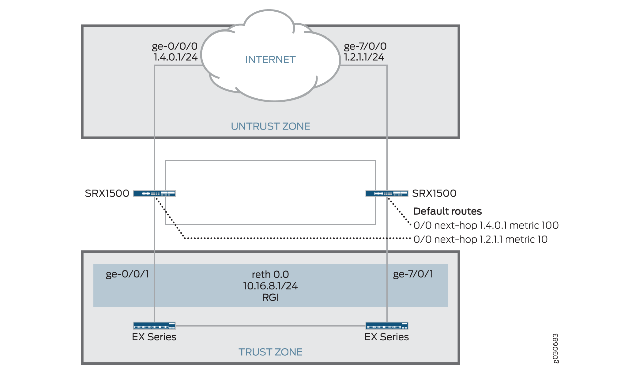
In this scenario, two Internet connections are used, with one being preferred. The connection to the trust zone is done by using a redundant Ethernet interface to provide LAN redundancy for the devices in the trust zone. This scenario describes two failover cases in which sessions originate in the trust zone with a destination of the Internet (untrust zone).
- Understanding Failures in the Trust Zone Redundant Ethernet Interface
- Understanding Failures in the Untrust Zone Interfaces
Understanding Failures in the Trust Zone Redundant Ethernet Interface
Under normal operating conditions, traffic flows from the trust zone interface ge-0/0/1, belonging to reth0.0, to the Internet. Because the primary Internet connection is on node 0, sessions are created in node 0 and synced to node 1. However, sessions are only active on node 0.
A failure in interface ge-0/0/1 triggers a failover of the redundancy group, causing interface ge-7/0/1 in node 1 to become active. After the failover, traffic arrives at node 1. After session lookup, the traffic is sent to node 0 because the session is active on this node. Node 0 then processes the traffic and forwards it to the Internet. The return traffic follows a similar process. The traffic arrives at node 0 and gets processed for security purposes—for example, antispam scanning, antivirus scanning, and application of security policies—on node 0 because the session is anchored to node 0. The packet is then sent to node 1 through the fabric interface for egress processing and eventual transmission out of node 1 through interface ge-7/0/1.
Understanding Failures in the Untrust Zone Interfaces
In this case, sessions are migrated from node to node. Under normal operating conditions, traffic is processed by only node 0. A failure of interface ge-0/0/0 on node 0 causes a change in the routing table, so that it now points to interface ge-7/0/0 in node 1. After the failure, sessions in node 0 become inactive, and the passive sessions in node 1 become active. Traffic arriving from the trust zone is still received on interface ge-0/0/1, but is forwarded to node 1 for processing. After traffic is processed in node 1, it is forwarded to the Internet through interface ge-7/0/0.
In this chassis cluster configuration, redundancy group 1 is used to control the redundant Ethernet interface connected to the trust zone. As configured in this scenario, redundancy group 1 fails over only if interface ge-0/0/1 or ge-7/0/1 fails, but not if the interfaces connected to the Internet fail. Optionally, the configuration could be modified to permit redundancy group 1 to monitor all interfaces connected to the Internet and fail over if an Internet link were to fail. So, for example, the configuration can allow redundancy group 1 to monitor ge-0/0/0 and make ge-7/0/1 active for reth0 if the ge-0/0/0 Internet link fails. (This option is not described in the following configuration examples.)
See Also
Example: Configuring an Asymmetric Chassis Cluster Pair
This example shows how to configure a chassis cluster to allow asymmetric routing. Configuring asymmetric routing for a chassis cluster allows traffic received on either device to be processed seamlessly.
Requirements
Before you begin:
-
Physically connect a pair of devices together, ensuring that they are the same models. This example uses a pair of SRX1500 or SRX1600 devices.
-
To create the fabric link, connect a Gigabit Ethernet interface on one device to another Gigabit Ethernet interface on the other device.
-
To create the control link, connect the control port of the two SRX1500 devices.
-
-
Connect to one of the devices using the console port. (This is the node that forms the cluster.)
-
Set the cluster ID and node number.
user@host> set chassis cluster cluster-id 1 node 0 reboot
-
-
Connect to the other device using the console port.
-
Set the cluster ID and node number.
user@host> set chassis cluster cluster-id 1 node 1 reboot
-
Overview
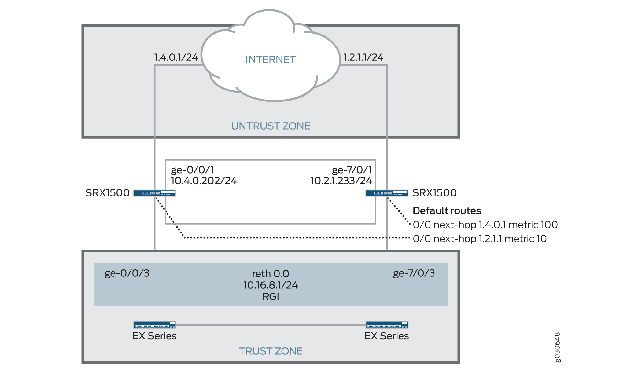
In this example, a chassis cluster provides asymmetric routing. As illustrated in Figure 2, two Internet connections are used, with one being preferred. The connection to the trust zone is provided by a redundant Ethernet interface to provide LAN redundancy for the devices in the trust zone.
In this example, you configure group (applying the configuration
with the apply-groups command) and chassis cluster information.
Then you configure security zones and security policies. See Table 1 through Table 4.
|
Feature |
Name |
Configuration Parameters |
|---|---|---|
|
Groups |
node0 |
|
|
node1 |
|
|
Feature |
Name |
Configuration Parameters |
|---|---|---|
|
Fabric links |
fab0 |
Interface: ge-0/0/7 |
|
fab1 |
Interface: ge-7/0/7 |
|
|
Heartbeat interval |
– |
1000 |
|
Heartbeat threshold |
– |
3 |
|
Redundancy group |
1 |
|
|
Interface monitoring
|
||
|
Number of redundant Ethernet interfaces |
– |
1 |
|
Interfaces |
ge-0/0/1 |
|
|
ge-7/0/1 |
|
|
|
ge-0/0/3 |
Redundant parent: reth0 |
|
|
ge-7/0/3 |
Redundant parent: reth0 |
|
|
reth0 |
|
|
|
Name |
Configuration Parameters |
|---|---|
|
trust |
The reth0.0 interface is bound to this zone. |
|
untrust |
The ge-0/0/1 and ge-7/0/1 interfaces are bound to this zone. |
|
Purpose |
Name |
Configuration Parameters |
|---|---|---|
|
This security policy permits traffic from the trust zone to the untrust zone. |
ANY |
|
Configuration
Procedure
CLI Quick Configuration
To quickly configure this example, copy the
following commands, paste them into a text file, remove any line breaks,
change any details necessary to match your network configuration,
copy and paste the commands into the CLI at the [edit] hierarchy
level, and then enter commit from configuration mode.
{primary:node0}[edit]
set groups node0 system host-name srxseries-1
set groups node0 interfaces fxp0 unit 0 family inet address 192.168.100.50/24
set groups node1 system host-name srxseries-2
set groups node1 interfaces fxp0 unit 0 family inet address 192.168.100.51/24
set apply-groups “${node}”
set interfaces fab0 fabric-options member-interfaces ge-0/0/7
set interfaces fab1 fabric-options member-interfaces ge-7/0/7
set chassis cluster reth-count 1
set chassis cluster heartbeat-interval 1000
set chassis cluster heartbeat-threshold 3
set chassis cluster redundancy-group 1 node 0 priority 100
set chassis cluster redundancy-group 1 node 1 priority 1
set chassis cluster redundancy-group 1 interface-monitor ge-0/0/3 weight 255
set chassis cluster redundancy-group 1 interface-monitor ge-7/0/3 weight 255
set interfaces ge-0/0/1 unit 0 family inet address 1.4.0.202/24
set interfaces ge-0/0/3 gigether-options redundant-parent reth0
set interfaces ge-7/0/1 unit 0 family inet address 10.2.1.233/24
set interfaces ge-7/0/3 gigether-options redundant-parent reth0
set interfaces reth0 unit 0 family inet address 10.16.8.1/24
set routing-options static route 0.0.0.0/0 qualified-next-hop 10.4.0.1 metric 10
set routing-options static route 0.0.0.0/0 qualified-next-hop 10.2.1.1 metric 100
set security zones security-zone untrust interfaces ge-0/0/1.0
set security zones security-zone untrust interfaces ge-7/0/1.0
set security zones security-zone trust interfaces reth0.0
set security policies from-zone trust to-zone untrust policy ANY match source-address any
set security policies from-zone trust to-zone untrust policy ANY match destination-address any
set security policies from-zone trust to-zone untrust policy ANY match application any
set security policies from-zone trust to-zone untrust policy ANY then permit
Step-by-Step Procedure
To configure an asymmetric chassis cluster pair:
-
Configure the management interface.
{primary:node0}[edit] user@host# set groups node0 system host-name srxseries-1 user@host# set groups node0 interfaces fxp0 unit 0 family inet address 192.168.100.50/24 user@host# set groups node1 system host-name srxseries-2 user@host#set groups node1 interfaces fxp0 unit 0 family inet address 192.168.100.51/24 user@host# set apply-groups “${node}” -
Configure the fabric interface.
{primary:node0}[edit] user@host# set interfaces fab0 fabric-options member-interfaces ge-0/0/7 user@host# set interfaces fab1 fabric-options member-interfaces ge-7/0/7 -
Configure the number of redundant Ethernet interfaces.
{primary:node0}[edit] user@host# set chassis cluster reth-count 1 -
Configure the redundancy groups.
{primary:node0}[edit] user@host# set chassis cluster heartbeat-interval 1000 user@host# set chassis cluster heartbeat-threshold 3 user@host# set chassis cluster node 0 user@host# set chassis cluster node 1 user@host# set chassis cluster redundancy-group 1 node 0 priority 100 user@host# set chassis cluster redundancy-group 1 node 1 priority 1 user@host# set chassis cluster redundancy-group 1 interface-monitor ge-0/0/3 weight 255 user@host# set chassis cluster redundancy-group 1 interface-monitor ge-7/0/3 weight 255 -
Configure the redundant Ethernet interfaces.
{primary:node0}[edit] user@host# set interfaces ge-0/0/1 unit 0 family inet address 1.4.0.202/24 user@host# set interfaces ge-0/0/3 gigether-options redundant-parent reth0 user@host# set interfaces ge-7/0/1 unit 0 family inet address 10.2.1.233/24 user@host# set interfaces ge-7/0/3 gigether-options redundant-parent reth0 user@host# set interfaces reth0 unit 0 family inet address 10.16.8.1/24 -
Configure the static routes (one to each ISP, with preferred route through ge-0/0/1).
{primary:node0}[edit] user@host# set routing-options static route 0.0.0.0/0 qualified-next-hop 10.4.0.1 metric 10 user@host# set routing-options static route 0.0.0.0/0 qualified-next-hop 10.2.1.1 metric 100 -
Configure the security zones.
{primary:node0}[edit] user@host# set security zones security-zone untrust interfaces ge-0/0/1.0 user@host# set security zones security-zone untrust interfaces ge-7/0/1.0 user@host# set security zones security-zone trust interfaces reth0.0 -
Configure the security policies.
{primary:node0}[edit]
user@host# set security policies from-zone trust to-zone untrust policy ANY match source-address any
user@host# set security policies from-zone trust to-zone untrust policy ANY match destination-address any
user@host# set security policies from-zone trust to-zone untrust policy ANY match application any
user@host# set security policies from-zone trust to-zone untrust policy ANY then permit
Results
From operational mode, confirm your configuration by
entering the show configuration command. If the output
does not display the intended configuration, repeat the configuration
instructions in this example to correct it.
For brevity, this show command output includes only
the configuration that is relevant to this example. Any other configuration
on the system has been replaced with ellipses (...).
user@host> show configuration
version x.xx.x;
groups {
    node0 {
        system {
            host-name srxseries-1;
        }
        interfaces {
            fxp0 {
                unit 0 {
                    family inet {
                        address 192.168.100.50/24;
                    }
                }
            }
        }
    }
    node1 {
        system {
            host-name srxseries-2;
            interfaces {
                fxp0 {
                    unit 0 {
                        family inet {
                            address 192.168.100.51/24;
                        }
                    }
                }
            }
        }
    }
    apply-groups "${node}";
    chassis {
        cluster {
            reth-count 1;
            heartbeat-interval 1000;
            heartbeat-threshold 3;
            redundancy-group 1 {
                node 0 priority 100;
                node 1 priority 1;
                interface-monitor {
                    ge-0/0/3 weight 255;
                    ge-7/0/3 weight 255;
                }
            }
        }
    }
    interfaces {
        ge-0/0/3 {
            gigether–options {
                redundant–parent reth0;
            }
        }
        ge-7/0/3 {
            gigether–options {
                redundant–parent reth0;
            }
        }
        ge–0/0/1 {
            unit 0 {
                family inet {
                address 10.4.0.202/24;
                }
            }
        }
        ge–7/0/1 {
            unit 0 {
                family inet {
                address 10.2.1.233/24;
                }
            }
        }
        fab0 {
            fabric–options {
                member–interfaces {
                    ge–0/0/7;
                }
            }
        }
        fab1 {
            fabric–options {
                member–interfaces {
                    ge–7/0/7;
                }
            }
        }
        reth0 {
            gigether–options {
                redundancy–group 1;
            }
            unit 0 {
                family inet {
                    address 10.16.8.1/24;
                }
            }
        }
    }
...
routing-options {
    static {
        route 0.0.0.0/0 {
            next-hop 10.4.0.1;
            metric 10;
        }
    }
}
routing-options {
    static {
        route 0.0.0.0/0 {
            next-hop 10.2.1.1;
            metric 100;
        }
    }
}
security {
    zones {
        security–zone untrust {
            interfaces {
                ge-0/0/1.0;
                ge-7/0/1.0;
            }
        }
        security–zone trust {
            interfaces {
                reth0.0;
            }
        }
    }
    policies {
        from-zone trust to-zone untrust {
            policy ANY {
                match {
                    source-address any;
                    destination-address any;
                    application any;
                }
                then {
                    permit;
                }
            }
        }
    }
}
If you are done configuring the device, enter commit from configuration mode.
Verification
Confirm that the configuration is working properly.
- Verifying Chassis Cluster Status
- Verifying Chassis Cluster Interfaces
- Verifying Chassis Cluster Statistics
- Verifying Chassis Cluster Control Plane Statistics
- Verifying Chassis Cluster Data Plane Statistics
- Verifying Chassis Cluster Redundancy Group Status
- Troubleshooting with Logs
Verifying Chassis Cluster Status
Purpose
Verify the chassis cluster status, failover status, and redundancy group information.
Action
From operational mode, enter the show chassis cluster
status command.
{primary:node0}
user@host> show chassis cluster status
Cluster ID: 1
Node                       Priority     Status    Preempt  Manual failover

Redundancy group: 1 , Failover count: 1
    node0                   100         primary   no       no
    node1                   1           secondary no       no
Verifying Chassis Cluster Interfaces
Purpose
Verify information about chassis cluster interfaces.
Action
From operational mode, enter the show chassis cluster
interfaces command.
{primary:node0}
user@host> show chassis cluster interfaces
Control link name: fxp1

Redundant-ethernet Information:
    Name         Status      Redundancy-group
    reth0        Up          1

Interface Monitoring:
    Interface         Weight    Status    Redundancy-group
    ge-0/0/3          255       Up        1
    ge-7/0/3          255       Up        1
Verifying Chassis Cluster Statistics
Purpose
Verify information about the statistics of the different objects being synchronized, the fabric and control interface hellos, and the status of the monitored interfaces in the cluster.
Action
From operational mode, enter the show chassis cluster
statistics command.
{primary:node0}
user@host> show chassis cluster statistics

Control link statistics:
    Control link 0:
        Heartbeat packets sent: 228
        Heartbeat packets received: 2370
        Heartbeat packets errors: 0
Fabric link statistics:
    Child link 0
        Probes sent: 2272
        Probes received: 597
Services Synchronized:
    Service name                              RTOs sent    RTOs received
    Translation context                       0            0
    Incoming NAT                              0            0
    Resource manager                          6            0
    Session create                            160          0
    Session close                             147          0
    Session change                            0            0
    Gate create                               0            0
    Session ageout refresh requests           0            0
    Session ageout refresh replies            0            0
    IPSec VPN                                 0            0
    Firewall user authentication              0            0
    MGCP ALG                                  0            0
    H323 ALG                                  0            0
    SIP ALG                                   0            0
    SCCP ALG                                  0            0
    PPTP ALG                                  0            0
    RPC ALG                                   0            0
    RTSP ALG                                  0            0
    RAS ALG                                   0            0
    MAC address learning                      0            0
    GPRS GTP                                  0            0
Verifying Chassis Cluster Control Plane Statistics
Purpose
Verify information about chassis cluster control plane statistics (heartbeats sent and received) and the fabric link statistics (probes sent and received).
Action
From operational mode, enter the show chassis cluster
control-plane statistics command.
{primary:node0}
user@host> show chassis cluster control-plane statistics

Control link statistics:
    Control link 0:
        Heartbeat packets sent: 258689
        Heartbeat packets received: 258684
        Heartbeat packets errors: 0
Fabric link statistics:
    Child link 0
        Probes sent: 258681
        Probes received: 258681
Verifying Chassis Cluster Data Plane Statistics
Purpose
Verify information about the number of RTOs sent and received for services.
Action
From operational mode, enter the show chassis cluster
data-plane statistics command.
{primary:node0}
user@host> show chassis cluster data-plane statistics

Services Synchronized:
    Service name                              RTOs sent    RTOs received
    Translation context                       0            0
    Incoming NAT                              0            0
    Resource manager                          6            0
    Session create                            160          0
    Session close                             147          0
    Session change                            0            0
    Gate create                               0            0
    Session ageout refresh requests           0            0
    Session ageout refresh replies            0            0
    IPSec VPN                                 0            0
    Firewall user authentication              0            0
    MGCP ALG                                  0            0
    H323 ALG                                  0            0
    SIP ALG                                   0            0
    SCCP ALG                                  0            0
    PPTP ALG                                  0            0
    RPC ALG                                   0            0
    RTSP ALG                                  0            0
    RAS ALG                                   0            0
    MAC address learning                      0            0
    GPRS GTP                                  0            0
Verifying Chassis Cluster Redundancy Group Status
Purpose
Verify the state and priority of both nodes in a cluster and information about whether the primary node has been preempted or whether there has been a manual failover.
Action
From operational mode, enter the chassis cluster
status redundancy-group command.
{primary:node0}
user@host> show chassis cluster status redundancy-group 1
Cluster ID: 1
    Node               Priority    Status    Preempt  Manual failover

	Redundancy-Group: 1, Failover count: 1
    node0              100          primary   no       no
    node1              1            secondary no       no
Troubleshooting with Logs
Purpose
Use these logs to identify any chassis cluster issues. You must run these logs on both nodes.
Action
From operational mode, enter these show commands.
user@host> show log jsrpd
user@host> show log chassisd
user@host> show log messages
user@host> show log dcd
user@host> show traceoptions