ON THIS PAGE
Example: Configuring an Active/Active Layer 3 Cluster Deployment
This example shows how to set up basic active/active chassis clustering on a pair of SRX5000 line of Firewalls..
Requirements
This example uses the following hardware and software components:
-
Two Juniper Networks SRX5800 Services Gateways with identical hardware configurations running Junos OS Release 18.1R1 or later.
-
Two Juniper Networks EX9214 Ethernet Switches running Junos OS Release 18.1R1 or later.
-
Any Ethernet switch can be used here.
-
Before you begin:
-
Physically connect the two SRX Services Gateways (back-to-back for the fabric and control ports).
This configuration example has been tested using the software release listed and is assumed to work on all later releases.
Overview
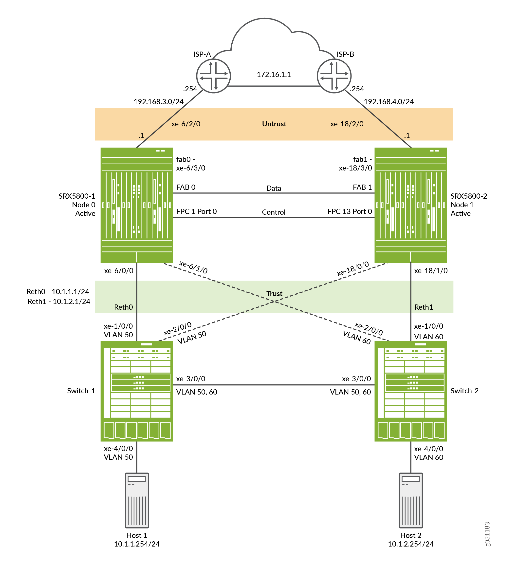
A chassis cluster consists of two SRX Series Firewalls with identical hardware. Active/active clustering on SRX Series Firewalls is supported for those environments that want to maintain traffic on both chassis cluster members whenever possible. In an active/active deployment, only the data plane is in active/active mode; the control plane is in active/passive mode. This allows one control plane to control both chassis members as a single logical device, allowing the control plane to fail over to the other device in case of failure. Having only the data plane in active/active mode allows the data plane to failover independently of the control plane.
Active/active configuration also allows ingress interfaces to be on one cluster device and the egress interfaces to be on the other. When the ingress and egress interfaces are set up on different devices, the data traffic must pass through the data fabric to the other cluster device and out the egress interface.
This active/active chassis clustering example requires you to configure two redundant Ethernet (reth) interfaces—reth0 and reth1—for each node and ensure they are connected together by one or more switches. A reth interface bundles the two physical interfaces (one from each node) together. A reth interface is assigned to a redundancy group.
Figure 1 shows the topology used in this example.
Configuration
To configure this example, perform the following procedures:
- Configuring the Control Ports
- Enabling Cluster Mode
- Configuring Cluster Parameters
- Configuring Zones, Policies, NAT, and Routes
- Configure EX9214-1
- Configure EX9214-2
Configuring the Control Ports
Step-by-Step Procedure
Configure the control port for each device.
Select FPC 1 and FPC 13, because the central point (CP) is always on the lowest SPC/SPU in the cluster (for this example, it is slot 0). For maximum reliability, place the control ports on a separate SPC from the central point (this example uses the SPC in slot 1).
Control port configuration is required only for SRX5600 and SRX5800 devices.
-
Configure the control ports and commit the configuration:
user@host# set chassis cluster control-ports fpc 1 port 0
user@host# set chassis cluster control-ports fpc 13 port 0
user@host# commit and-quit
Enabling Cluster Mode
Step-by-Step Procedure
Assign a cluster ID and node ID to each device.
Set the two devices to cluster mode by adding a cluster ID and node ID on
each and rebooting. You can configure the system to boot automatically by
including the reboot parameter in the set command.
Since there is only a single cluster on the segments, this example uses cluster ID 1 with Device SRX5800-1 as node 0 and Device SRX5800-2 as node 1.
To set the two devices in cluster mode:
-
Enable cluster mode on SRX5800-1 (node 0).
user@host> set chassis cluster cluster-id 1 node 0 reboot
-
Enable cluster mode on SRX5800-2 (node 1).
user@host> set chassis cluster cluster-id 1 node 1 reboot
Note:If you have multiple SRX device clusters on a single broadcast domain, make sure that you assign different cluster IDs to each cluster to avoid MAC address conflicts.
When the system reboots, the nodes come up as a cluster. From this point forward, configuration of the cluster is synchronized between the node members, and the two separate devices function as one device.
Configuring Cluster Parameters
Step-by-Step Procedure
In cluster mode, all commands and configuration are applied to both nodes.
To configure chassis cluster settings:
-
Configure a fabric (data) port on each device to enable traffic to pass from one device to the other for cases where traffic arrives on an ingress interface on one node but leaves on another node.
Note:A 10-Gigabit Ethernet connection is recommended for active/active deployments.
user@host# set interfaces fab0 fabric-options member-interfaces xe-6/3/0
user@host# set interfaces fab1 fabric-options member-interfaces xe-18/3/0
-
Configure each device’s fxp0 interface for out-of-band management. Assign a separate IP address for each device (control plane) of the cluster.
Because the SRX Services Gateway chassis cluster configuration is contained within a single common configuration, to assign some elements of the configuration to a specific member only, use the Junos OS node-specific configuration method called groups. The
set apply-groups ${node}command uses the node variable to define how the groups are applied to the nodes. Each node recognizes its number and accepts the configuration accordingly.user@host# set groups node0 system host-name SRX5800-1 user@host# set groups node0 interfaces fxp0 unit 0 family inet address 10.52.43.57/19 user@host# set groups node1 system host-name SRX5800-2 user@host# set groups node1 interfaces fxp0 unit 0 family inet address 10.52.52.27/19 user@host# set apply-groups ${node} -
Configure redundancy groups for chassis clustering.
Each node has interfaces in a redundancy group. Redundancy group 0 controls the control plane, it defines which node will be the primary. Redundancy group 1+ controls the data plane and includes the data plane ports. This active/active clustering mode example uses 2 reth interfaces with redundancy groups 0, 1, and 2.
As part of redundancy group configuration, you must also define the priority for control plane and data plane—which device is preferred for the control plane, and which device is preferred for the data plane. (For chassis clustering, higher priority is preferred.)
Note:The control plane (redundancy group 0) and data plane (redundancy group 1+) can each be active on a different chassis. However, for this example, we recommend having both the control and data plane active on the same chassis member. Redundancy group 0 (RG0) and redundancy group 1 (RG1) default to the active state on node 0, whereas, redundancy group 2 (RG2) defaults to active state on node 1.
user@host# set chassis cluster redundancy-group 0 node 0 priority 129
user@host# set chassis cluster redundancy-group 0 node 1 priority 128
user@host# set chassis cluster redundancy-group 1 node 0 priority 129
user@host# set chassis cluster redundancy-group 1 node 1 priority 128
user@host# set chassis cluster redundancy-group 2 node 0 priority 128
user@host# set chassis cluster redundancy-group 2 node 1 priority 129
-
Configure the data interfaces on the platform so that in the event of a data plane failover, the other chassis cluster member can take over the connection seamlessly.
Define the following items:
-
The maximum number of reth interfaces for the cluster, so that the system can allocate the appropriate resources for them.
user@host# set chassis cluster reth-count 2 -
The reth interface information such as the IP address of the interface.
user@host# set interfaces reth0 unit 0 family inet address 10.1.1.1/24
user@host# set interfaces reth1 unit 0 family inet address 10.1.2.1/24
-
Membership information of the member interfaces to reth interfaces.
user@host# set interfaces xe-6/0/0 gigether-options redundant-parent reth0
user@host# set interfaces xe-6/1/0 gigether-options redundant-parent reth1
user@host# set interfaces xe-18/0/0 gigether-options redundant-parent reth0
user@host# set interfaces xe-18/1/0 gigether-options redundant-parent reth1
-
The mapping of reth interfaces to redundancy groups.
user@host# set interfaces reth0 redundant-ether-options redundancy-group 1
user@host# set interfaces reth1 redundant-ether-options redundancy-group 2
-
-
Configure the behavior in case of a failure.
Each interface is configured with a weight value that is deducted from the redundancy group threshold of 255 upon a link loss. When a redundancy group threshold reaches 0, that redundancy group fails over to the secondary node.
Note:If the
control-link-recoveryfeature is not enabled, a manual reboot is required to bring the secondary node back into sync with the primary node.user@host# set chassis cluster redundancy-group 1 interface-monitor xe-6/0/0 weight 255 user@host# set chassis cluster redundancy-group 2 interface-monitor xe-6/1/0 weight 255 user@host# set chassis cluster redundancy-group 1 interface-monitor xe-18/0/0 weight 255 user@host# set chassis cluster redundancy-group 2 interface-monitor xe-18/1/0 weight 255 user@host# set chassis cluster control-link-recovery
Note:Individual VLANs on an interface are not monitored. Only interfaces as a whole are monitored.
This step completes the chassis cluster configuration.
-
Configure other interfaces that do not belong to the reth interfaces. These are the upstream interfaces towards the ISPs.
user@host# set interface xe-6/2/0 unit 0 family inet address 192.168.3.1/24
user@host# set interface xe-18/2/0 unit 0 family inet address 192.168.4.1/24
The following sections describe how to configure zones, security policies, NAT, routing, and the EX9214 Core Switches to complete the deployment scenario.
Configuring Zones, Policies, NAT, and Routes
Step-by-Step Procedure
Configure and connect the reth interfaces to the appropriate zones and define a security policy that permits outbound traffic. Also, for this example we will use a default route and NAT to enable end hosts to reach the Internet.
To configure zones, policies, NAT, and routes:
-
Assign the interfaces to the appropriate zones.
user@host# set security zones security-zone trust interfaces reth0.0
user@host# set security zones security-zone trust interfaces reth1.0
user@host# set security zones security-zone untrust interfaces xe-6/2/0.0
user@host# set security zones security-zone untrust interfaces xe-18/2/0.0
-
Configure a policy to allow traffic from the hosts in the trust zone to the Internet.
user@host# set security policies from-zone trust to-zone untrust policy allow match source-address any
user@host# set security policies from-zone trust to-zone untrust policy allow match destination-address any
user@host# set security policies from-zone trust to-zone untrust policy allow match application any
user@host# set security policies from-zone trust to-zone untrust policy allow then permit
-
Configure source NAT for outbound traffic.
user@host# set security nat source rule-set internet from zone trust
user@host# set security nat source rule-set internet to zone untrust
user@host# set security nat source rule-set internet rule rule1 match source-address 10.1.0.0/16
user@host# set security nat source rule-set internet rule rule1 then source-nat interface
-
Define a default static route to enable hosts to reach the Internet.
user@host# set routing-options static route 0.0.0.0/0 next-hop 192.168.3.254 user@host# set routing-options static route 0.0.0.0/0 qualified-next-hop 192.168.4.254 preference 7 user@host# set routing-options static route 10.0.0.0/8 next-hop 10.52.63.254 -
Configure OSPF.
user@host# set protocols ospf area 0.0.0.0 interface reth0.0
user@host# set protocols ospf area 0.0.0.0 interface reth1.0
user@host# set protocols ospf area 0.0.0.0 interface reth2.0
user@host# set protocols ospf area 0.0.0.0 interface reth3.0
Configure EX9214-1
Step-by-Step Procedure
For the EX9214-1, the following commands provide configuration only as it pertains to this active/active example for the SRX5800, most notably the VLANs, routing, and interface configuration.
-
Configure the interfaces.
user@host# set interfaces xe-1/0/0 unit 0 family ethernet-switching interface-mode access
user@host# set interfaces xe-1/0/0 unit 0 family ethernet-switching vlan members SRX5800-RETH0
user@host# set interfaces xe-2/0/0 unit 0 family ethernet-switching interface-mode access
user@host# set interfaces xe-2/0/0 unit 0 family ethernet-switching vlan members SRX5800-RETH0
user@host# set interfaces xe-3/0/0 unit 0 family ethernet-switching interface-mode trunk
user@host# set interfaces xe-3/0/0 unit 0 family ethernet-switching vlan members SRX5800-RETH1
user@host# set interfaces xe-3/0/0 unit 0 family ethernet-switching vlan members SRX5800-RETH0
user@host# set interfaces ge-4/0/0 unit 0 family ethernet-switching interface-mode access
user@host# set interfaces ge-4/0/0 unit 0 family ethernet-switching vlan members SRX5800-RETH0
Note:The end host is sending untagged traffic.
-
Configure the VLANs.
user@host# set vlans SRX5800-RETH0 vlan-id 50
user@host# set vlans SRX5800-RETH1 vlan-id 60
-
Enable RSTP.
user@host# set protocols rstp interface all
Note:In this example, RSTP is not strictly required as there is no Layer 2 loop. However, a typical environment would likely have more switches, which would require the protocol to be enabled.
Configure EX9214-2
Step-by-Step Procedure
To configure the EX9214-2:
-
Configure the interfaces.
user@host# set interfaces xe-1/0/0 unit 0 family ethernet-switching interface-mode access
user@host# set interfaces xe-1/0/0 unit 0 family ethernet-switching vlan members SRX5800-RETH1
user@host# set interfaces xe-2/0/0 unit 0 family ethernet-switching interface-mode access
user@host# set interfaces xe-2/0/0 unit 0 family ethernet-switching vlan members SRX5800-RETH1
user@host# set interfaces xe-3/0/0 unit 0 family ethernet-switching interface-mode trunk
user@host# set interfaces xe-3/0/0 unit 0 family ethernet-switching vlan members SRX5800-RETH0
user@host# set interfaces xe-3/0/0 unit 0 family ethernet-switching vlan members SRX5800-RETH1
user@host# set interfaces ge-4/0/0 unit 0 family ethernet-switching interface-mode access
user@host# set interfaces ge-4/0/0 unit 0 family ethernet-switching vlan members SRX5800-RETH1
Note:The end host is sending untagged traffic.
-
Configure the VLANs.
user@host# set vlans SRX5800-RETH0 vlan-id 50
user@host# set vlans SRX5800-RETH1 vlan-id 60
-
Enable RSTP.
user@host# set protocols rstp interface all
Note:In this example, RSTP is not strictly required as there is no Layer 2 loop. However, a typical environment would likely have more switches, which would require the protocol to be enabled.
Verification
Confirm that the configuration is working properly.
- Verifying Chassis Cluster Status
- Verifying Chassis Cluster Interfaces
- Verifying Chassis Cluster Statistics
- Verifying Chassis Cluster Control Plane Statistics
- Verifying Chassis Cluster Data Plane Statistics
- Verifying Chassis Cluster Redundancy Group Status
- Troubleshooting with Logs
Verifying Chassis Cluster Status
Purpose
Verify the chassis cluster status, failover status, and redundancy group information.
Action
From operational mode, enter the show chassis cluster
status command.
{primary:node0}
user@host>show chassis cluster status

Monitor Failure codes:
    CS  Cold Sync monitoring        FL  Fabric Connection monitoring
    GR  GRES monitoring             HW  Hardware monitoring
    IF  Interface monitoring        IP  IP monitoring
    LB  Loopback monitoring         MB  Mbuf monitoring
    NH  Nexthop monitoring          NP  NPC monitoring
    SP  SPU monitoring              SM  Schedule monitoring
    CF  Config Sync monitoring

Cluster ID: 1
Node   Priority Status         Preempt Manual   Monitor-failures

Redundancy group: 0 , Failover count: 1
node0  129      primary        no      no       None
node1  128      secondary      no      no       None

Redundancy group: 1 , Failover count: 1
node0  129      primary        no      no       None
node1  128      secondary      no      no       None

Redundancy group: 2 , Failover count: 0
node0  128      secondary      no      no       None
node1  129      primary        no      no       None
Meaning
The sample output shows the status of the primary and secondary nodes and that there are no manual fail overs.
Verifying Chassis Cluster Interfaces
Purpose
Verify information about chassis cluster interfaces.
Action
From operational mode, enter the show chassis cluster
interfaces command.
{primary:node0}
user@host> show chassis cluster interfaces

Control link status: Up

Control interfaces:
    Index   Interface   Monitored-Status   Internal-SA
    0       fxp1        Up                 Disabled

Fabric link status: Up

Fabric interfaces:
    Name    Child-interface    Status
                               (Physical/Monitored)
    fab0    xe-6/3/0           Up   / Up
    fab0
    fab1    xe-18/3/0          Up   / Up
    fab1

Redundant-ethernet Information:
    Name         Status      Redundancy-group
    reth0        Up          1
    reth1        Up          2

Redundant-pseudo-interface Information:
    Name         Status      Redundancy-group
    lo0          Up          0

Interface Monitoring:
    Interface         Weight    Status    Redundancy-group
    ge-6/0/0           255       Up        1
    ge-18/0/0          255       Up        1
    ge-6/1/0           255       Up        2
    ge-18/1/0          255       Up        2
Meaning
The sample output provides status information about the control and fabric links. It also shows each reth interface’s status, weight value, and redundancy group.
Verifying Chassis Cluster Statistics
Purpose
Verify information about chassis cluster services and control link statistics (heartbeats sent and received), fabric link statistics (probes sent and received), and the number of real-time objects (RTOs) sent and received for services.
Action
From operational mode, enter the show chassis cluster
statistics command.
{primary:node0}
user@host> show chassis cluster statistics

Control link statistics:
    Control link 0:
        Heartbeat packets sent: 258689
        Heartbeat packets received: 258684
        Heartbeat packets errors: 0
Fabric link statistics:
    Child link 0
        Probes sent: 258681
        Probes received: 258681
Services Synchronized:
    Service name                              RTOs sent    RTOs received
    Translation context                       0            0
    Incoming NAT                              0            0
    Resource manager                          6            0
    Session create                            161          0
    Session close                             148          0
    Session change                            0            0
    Gate create                               0            0
    Session ageout refresh requests           0            0
    Session ageout refresh replies            0            0
    IPSec VPN                                 0            0
    Firewall user authentication              0            0
    MGCP ALG                                  0            0
    H323 ALG                                  0            0
    SIP ALG                                   0            0
    SCCP ALG                                  0            0
    PPTP ALG                                  0            0
    RPC ALG                                   0            0
    RTSP ALG                                  0            0
    RAS ALG                                   0            0
    MAC address learning                      0            0
    GPRS GTP                                  0            0
Meaning
Use the sample output to:
-
Verify that the Heartbeat packets sent is incrementing.
-
Verify that the Heartbeat packets received is a number close to the number of Heartbeats packets sent.
-
Verify that the Heartbeats packets errors is zero.
This verifies that the heartbeat packets are being transmitted and received without errors.
Verifying Chassis Cluster Control Plane Statistics
Purpose
Verify information about chassis cluster control plane statistics (heartbeats sent and received) and the fabric link statistics (probes sent and received).
Action
From operational mode, enter the show chassis cluster
control-plane statistics command.
{primary:node0}
user@host>show chassis cluster control-plane statistics

Control link statistics:
    Control link 0:
        Heartbeat packets sent: 258689
        Heartbeat packets received: 258684
        Heartbeat packets errors: 0
Fabric link statistics:
    Child link 0
        Probes sent: 258681
        Probes received: 258681
Meaning
Use the sample output to:
-
Verify that the Heartbeat packets sent is incrementing.
-
Verify that the Heartbeat packets received is a number close to the number of Heartbeats packets sent.
-
Verify that the Heartbeats packets errors is zero.
This verifies that the heartbeat packets are being transmitted and received without errors.
Verifying Chassis Cluster Data Plane Statistics
Purpose
Verify information about the number of real-time objects (RTOs) sent and received for services.
Action
From operational mode, enter the show chassis cluster
data-plane statistics command.
{primary:node0}
user@host>show chassis cluster data-plane statistics

Services Synchronized:
    Service name                              RTOs sent    RTOs received
    Translation context                       0            0
    Incoming NAT                              0            0
    Resource manager                          6            0
    Session create                            161          0
    Session close                             148          0
    Session change                            0            0
    Gate create                               0            0
    Session ageout refresh requests           0            0
    Session ageout refresh replies            0            0
    IPSec VPN                                 0            0
    Firewall user authentication              0            0
    MGCP ALG                                  0            0
    H323 ALG                                  0            0
    SIP ALG                                   0            0
    SCCP ALG                                  0            0
    PPTP ALG                                  0            0
    RPC ALG                                   0            0
    RTSP ALG                                  0            0
    RAS ALG                                   0            0
    MAC address learning                      0            0
    GPRS GTP                                  0            0
Meaning
The sample output shows the number of RTOs sent and received for the various services.
Verifying Chassis Cluster Redundancy Group Status
Purpose
Verify the status of a redundancy group.
Action
From operational mode, enter the chassis cluster
status redundancy-group command.
{primary:node0}
user@host>show chassis cluster status redundancy-group 1

Monitor Failure codes:
    CS  Cold Sync monitoring        FL  Fabric Connection monitoring
    GR  GRES monitoring             HW  Hardware monitoring
    IF  Interface monitoring        IP  IP monitoring
    LB  Loopback monitoring         MB  Mbuf monitoring
    NH  Nexthop monitoring          NP  NPC monitoring
    SP  SPU monitoring              SM  Schedule monitoring
    CF  Config Sync monitoring

Cluster ID: 1
Node   Priority Status         Preempt Manual   Monitor-failures

Redundancy group: 1 , Failover count: 1
node0  129      primary        no      no       None
node1  128      secondary      no      no       None
Meaning
The sample output shows that redundancy group 1 is functioning normally, with no preemptions, manual fail overs, or other failures.
Troubleshooting with Logs
Purpose
Look at the system log files to identify any chassis cluster issues. You should look at the system log files on both nodes.
Action
From operational mode, enter these show log commands.
user@host> show log jsrpd
user@host> show log chassisd
user@host> show log messages
user@host> show log dcd
user@host> show traceoptions
Results
From operational mode, confirm your configuration by entering the
show configuration command. If the output does not
display the intended configuration, repeat the instructions in this
example to correct the configuration.
groups {
    node0 {
        system {
            host-name SRX5800-1;
        }
        interfaces {
            fxp0 {
                unit 0 {
                    family inet {
                        address 10.3.5.1/24;
                    }
                }
            }
        }
    }
    node1 {
        system {
            host-name SRX5800-2;
        }
        interfaces {
            fxp0 {
                unit 0 {
                    family inet {
                        address 10.3.5.2/24;
                    }
                }
            }
        }
    }
}
apply-groups “${node}”;
chassis {
    cluster {
        control-link-recovery;
        reth-count 2;
        control-ports {
            fpc 1 port 0;
            fpc 13 port 0;
        }
        redundancy-group 0 {
            node 0 priority 129;
            node 1 priority 128;
        }
        redundancy-group 1 {
            node 0 priority 129;
            node 1 priority 128;
            interface-monitor {
                xe-6/0/0 weight 255;
                xe-18/0/0 weight 255;
            }
        }
        redundancy-group 2 {
            node 0 priority 128;
            node 1 priority 129;
            interface-monitor {
                xe-6/1/0 weight 255;
                xe-18/1/0 weight 255;
            }
        }
    }
}
interfaces {
    xe-6/0/0 {
        gigether-options {
            redundant-parent reth0;
        }
    }
    xe-6/1/0 {
        gigether-options {
            redundant-parent reth1;
        }
    }
    xe-6/2/0 {
        unit 0 {
            family inet {
                address 192.168.3.1/24;
            }
        }
    }
    xe-18/0/0 {
        gigether-options {
            redundant-parent reth0;
        }
    }
    xe-18/1/0 {
        gigether-options {
            redundant-parent reth1;
        }
    }
    xe-18/2/0 {
        unit 0 {
            family inet {
                address 192.168.4.1/24;
            }
        }
    }
    fab0 {
        fabric-options {
            member-interfaces {
                xe-6/3/0;
            }
        }
    }
    fab1 {
        fabric-options {
            member-interfaces {
                xe-18/3/0;
            }
        }
    }
    reth0 {
        redundant-ether-options {
            redundancy-group 1;
        }
        unit 0 {
            family inet {
                address 10.1.1.1/24;
            }
        }
    }
    reth1 {
        redundant-ether-options {
            redundancy-group 2;
        }
        unit 0 {
            family inet {
                address 10.1.2.1/24;
            }
        }
    }
}
routing-options {
    static {
        route 0.0.0.0/0 {
            next-hop 192.168.3.254;
            qualified-next-hop 192.168.4.254 {
                preference 7;
            }
        }
    }
}
security {
    nat {
        source {
            rule-set internet {
                from zone trust;
                to zone untrust;
                rule rule1 {
                    match {
                        source-address 10.1.0.0/16;
                    }
                    then {
                        source-nat {
                            interface;
                        }
                    }
                }
            }
        }
    }
    policies {
        from-zone trust to-zone untrust {
            policy allow {
                match {
                    source-address any;
                    destination-address any;
                    application any;
                }
                then {
                    permit;
                }
            }
        }
    }
    zones {
        security-zone trust {
            interfaces {
                reth0.0;
                reth1.0;
            }
        }
        security-zone untrust {
            interfaces {
                xe-6/2/0.0;
                xe-18/2/0.0;
            }
        }
    }
}
If you are done configuring the device, enter commit
from configuration mode.