PTP Boundary Clock Overview
An IEEE 1588v2 boundary clock has multiple network connections and can act as a source (timeTransmitter) and a destination (timeReceiver) for synchronization messages. It synchronizes itself to a best timeTransmitter clock through a timeReceiver port and supports synchronization of remote clock clients to it on timeTransmitter ports.
PTP Boundary Clock
Boundary clocks can improve the accuracy of clock synchronization by reducing the number of 1588v2-unaware hops between the timeTransmitter and the timeReceiver. Boundary clocks can also be deployed to deliver better scale because they reduce the number of sessions and the number of packets per second on the timeTransmitter.
The boundary clock intercepts and processes all PTP messages and passes all other traffic.
The best timeTransmitter clock algorithm (BTCA) is used by the boundary clock to select the
best configured acceptable timeTransmitter clock that a boundary timeReceiver port can see.
To configure a boundary clock, include the boundary statement at the
[edit protocols ptp clock-mode] hierarchy level and at least one
timeTransmitter with the master statement and at least one timeReceiver
with the slave statement at the [edit protocols ptp]
hierarchy
level.
All PTP packets uses the best-effort queue instead of network control queue.
If clksyncd-service restart is initiated, then the show ptp lock
status detail CLI command output of Clock reference state
and 1pps reference state fields shows incorrect information. The
following is a sample of output for show ptp lock status detail:
user@host> show ptp lock-status detail
Lock Status:

Lock State    : 5 (PHASE ALIGNED)
Phase offset  : 0.000000010 sec
State since   : 2018-11-22 00:38:56 PST (00:10:18 ago)

Selected Master Details:
Upstream Master address    : 12.0.0.1
Slave interface            : xe-0/0/20.0
Clock reference state      : Clock locked
1pps reference state       : Clock qualified
Figure 1 illustrates two boundary clocks in a network in which the clock flow is from the upstream node (BC-1) to the downstream node (BC-2). This figure also applies to MX Series routers and QFX Series switches.
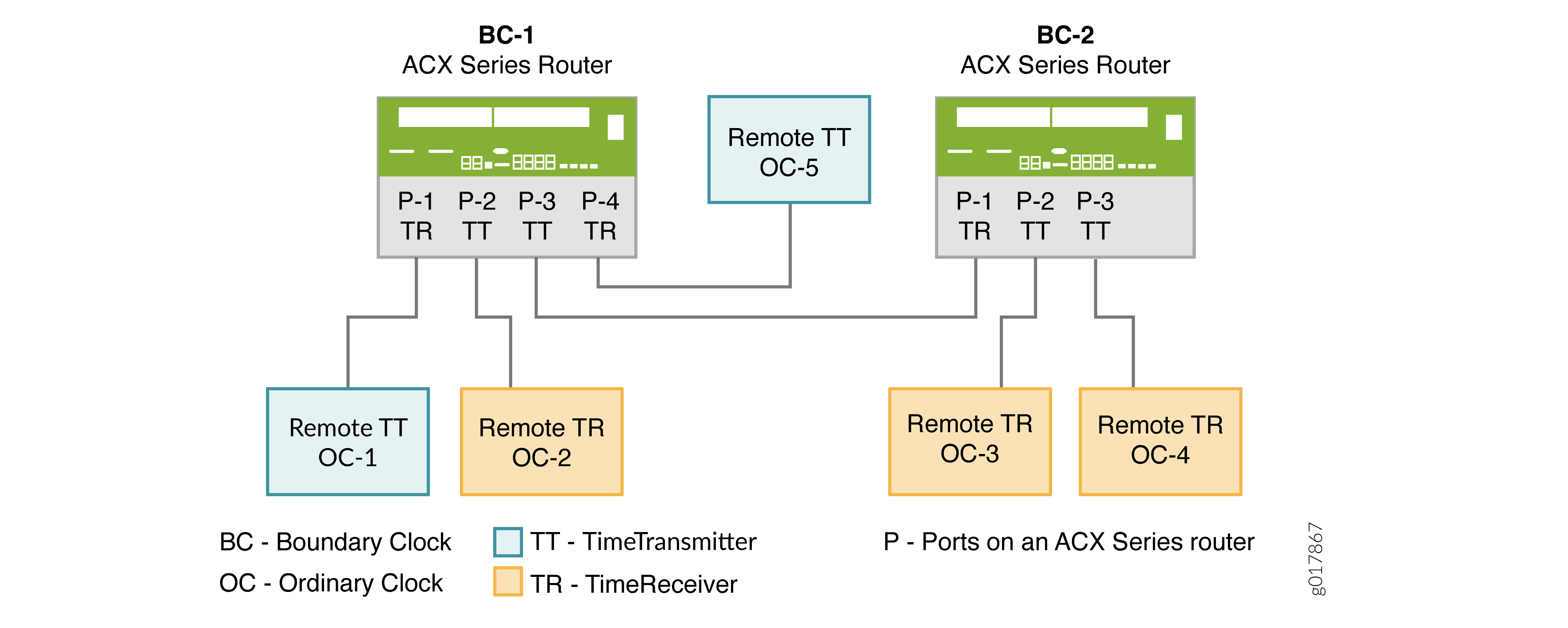
The first boundary clock—BC-1—has four ports. Each port is configured as follows:
-
BC-1 P-1 and BC-1 P-4 are boundary timeReceiver ports connected to two grandmaster clocks—OC-1 and OC-5. The grandmaster clocks are included as the clock sources in the timeReceiver port configurations. From the packets received on the timeReceiver ports, BC-1 selects the best timeTransmitter, synchronizes its clock, and generates PTP packets, which are sent over the timeTransmitter ports—BC-1 P-2 and BC-1 P-3—to the downstream timeReceiver clocks.
-
BC-1 P-2, a timeTransmitter port, is connected to OC-2, an ordinary remote timeReceiver. OC-2 is included as a clock client in BC-1 P-2’s timeTransmitter configuration, and so receives PTP packets from BC-1 P-2.
-
BC-1 P-3, a timeTransmitter port, is connected to BC-2 P-1, a remote boundary timeReceiver port. In this situation, the timeTransmitter port—BC-1 P-3—is included as a clock source in the configuration of the boundary timeReceiver port—BC-2 P-1. In addition, the boundary timeReceiver port—BC-2 P-1—is included as a clock client in the configuration of the timeTransmitter port—BC-1 P-3. With this configuration, the boundary timeReceiver—BC-2 P1—receives PTP packets from BC-1 P3.
The second boundary clock—BC-2—has three ports. Each port is configured as follows:
-
BC-2 P-1 is a boundary timeReceiver port connected to the upstream timeTransmitter port—BC-1 P3. As described previously, BC-2 P-1 receives PTP packets from BC-1 P3. The timeTransmitter ports—BC-2 P-2 and BC-2 P-3—synchronize their time from the packets received from BC-2 P1.
-
BC-2 P-2 and BC-2 P-3, boundary timeTransmitter ports, are connected to ordinary remote timeReceiver clocks—OC-3 and OC-4. OC-3 and OC-4 are included as clock clients in the configuration of the timeTransmitter ports—BC-2 P2 and BC-2 P-3. Both timeReceiver clocks receive PTP packets from the timeTransmitter boundary port to which they are connected.
In this example, the boundary clock synchronizes its clock from the packets received on its timeReceiver ports from the upstream timeTransmitter. The boundary clock then generates PTP packets, which are sent over the timeTransmitter port to downstream timeReceiver clocks. These packets are timestamped by the boundary clock by using its own time, which is synchronized to the selected upstream timeTransmitter.
Clock Clients
A clock client is the remote PTP host, which receives time from the PTP timeTransmitter and is in a timeReceiver relationship to the timeTransmitter.
The term timeReceiver is sometimes used to refer to the clock client.
A device acting as a timeTransmitter boundary clock supports the following types of downstream timeReceiver clocks:
-
Automatic timeReceiver—An automatic timeReceiver is configured with an IP address, which includes the subnet mask, indicating that any remote PTP host belonging to that subnet can join the timeTransmitter clock through a unicast negotiation. To configure an automatic timeReceiver, include the subnet mask in the
clock-client
                ip-address
statement at the [edit protocols ptp master interface interface-name unicast-mode] hierarchy level. -
Manual timeReceiver—A manual timeReceiver is configured with the
manualstatement at the [edit protocols ptp master interface interface-name unicast-mode clock-client ip-address local-ip-address local-ip-address] hierarchy level. A manual timeReceiver does not use unicast negotiation to join the timeTransmitter clock. Themanualstatement overrides theunicast negotiationstatement configured at the [edit protocols ptp] hierarchy level. As soon as you configure a manual timeReceiver, it starts receiving announce and synchronization packets. -
Secure timeReceiver—A secure timeReceiver is configured with an exact IP address of the remote PTP host, after which it joins a timeTransmitter clock through unicast negotiation. To configure a secure timeReceiver, include the exact IP address in the
clock-client ip-addressstatement at the [edit protocols ptp master interface interface-name unicast-mode] hierarchy level.
You can configure a maximum number of 512 timeReceiver clocks in the following combination:
-
256 automatic timeReceiver clocks
-
256 manual and secure timeReceiver clocks—Any combination of manual and secure timeReceiver clocks is allowed as long as the combined total amounts to 256.
Platform-Specific Boundary Clock Behavior
Use Feature Explorer to confirm platform and release support for specific features.
Use the following table to review platform-specific behaviors for your platform:
|
Platform |
Difference |
|---|---|
|
ACX Series |
|
|
MX and PTX Series |
|