APPENDIX: Example EVPN Multihoming Fabric Creation
The examples shown in the entire appendix section are made with functional testing in mind. Shortcuts are also made on WAN router integration which is not a production grade design. However, with the design below, you can easily evaluate how a new campus fabric is deployed.
Campus Fabric EVPN Multihoming Components
This configuration example uses the following devices:
- Two QFX5110 switches as distribution devices, software version: Junos OS Release 22.4R3-S2 or later.
- Two access layer EX4100 switches, software version: Junos OS Release 22.4R3-S2 or later.
- One SRX345 WAN router, software version: 21.2R3-S7 or later.
- Juniper APs.
- Two Linux desktops that act as wired clients.
Juniper Mist Wired Assurance
Juniper Mist Wired Assurance, through the Juniper Mist portal, can be used to centrally manage all Juniper switches. Juniper Mist Wired Assurance gives you full visibility into the devices that comprise your network’s access layer. The portal provides a user interface to access your architecture through the AI-driven cloud services with your Juniper Mist account. You can monitor, measure, and get alerts on key compliance metrics on the wired network. This includes switch version and PoE compliance, switch AP affinity, and VLAN insights.
The following link describes onboarding Juniper switches to the Juniper Mist cloud: https://www.juniper.net/documentation/us/en/quick-start/hardware/cloud-ready-switches/topics/topic-map/step-1-begin.html
Juniper Mist Wired Assurance, through the portal, is used to build Campus Fabric EVPN Multihoming from the ground up. This includes the following:
- Assignment of point-to-point (P2P) links between the core and distribution layers.
- Assignment of unique BGP AS numbers per device participating in the underlay and overlay.
- The creation of VRF instances allows you to logically segment traffic. This also includes the assignment of new or existing VLANs to each representative VRF.
- IP addressing of each Layer 3 gateway integrated routing and bridging (IRB) interface assigned to the distribution layer.
- IP addressing of each loopback interface.
- Configuration of routing policies for underlay and overlay connectivity.
- Optimized maximum transmission unit (MTU) settings for P2P underlay, Layer 3 IRB, and ESI-LAG bundles.
- Downloadable connection table (CSV format) that can be used by those involved in the physical buildout of the campus fabric.
- Graphical interface depicting all devices with BGP peering and physical link status.
For more information on Juniper Mist Wired Assurance, see: https://www.mist.com/documentation/category/wired-assurance/
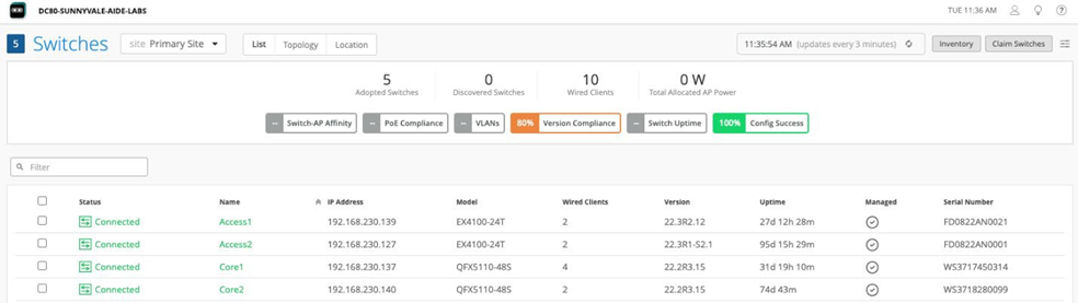
Juniper Mist Wired Assurance Switches
You must validate that each device participating in the campus fabric has been adopted or claimed and assigned to a site. The switches are named for respective layers in the fabric to facilitate building and operating the fabric.
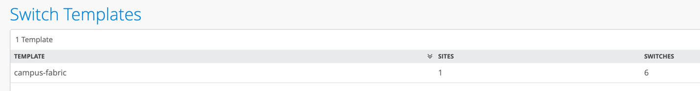
Templates
A key feature of switch management through the Juniper Mist cloud is to use templates and a hierarchical model to group the switches and make bulk updates. Templates provide uniformity and convenience, while the hierarchy (site and switch) provides both scale and granularity.
Templates and the hierarchical model mean that you can create a template configuration and then all the devices in each group inherit the template settings. When a conflict occurs, for example, when there are settings at both the site and organizational levels that apply to the same device, the narrower settings (in this case, the site settings) override the broader settings defined at the organization level.
Individual switches, at the bottom of the hierarchy, can inherit all or part of the configuration defined at the organization level, and again at the site level. Of course, individual switches can also have their own unique configurations.
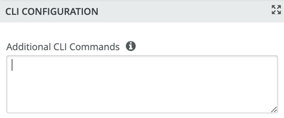
You can include individual CLI commands at any level of the hierarchy, which are then appended to all the switches in that group on an “AND” basis—that is, individual CLI settings are appended to the existing configuration (existing settings might be replaced or appended).
If you run CLI commands for items not native to the portal, this configuration data is applied last; overwriting existing configuration data within the same stanza. You can access the CLI command option from the switch template or individual switch configuration.
Under Organization -> Switch Templates, we use the following template:
We provide a copy of the following template in JSON format for importing into your own system for verification:
{
  "ntp_servers": [],
  "dns_servers": [
    "8.8.8.8",
    "9.9.9.9"
  ],
  "dns_suffix": [],
  "additional_config_cmds": [],
  "networks": {
    "vlan1099": {
      "vlan_id": 1099,
      "subnet": "10.99.99.0/24"
    },
    "vlan1088": {
      "vlan_id": 1088,
      "subnet": "10.88.88.0/24"
    },
    "vlan1033": {
      "vlan_id": 1033,
      "subnet": "10.33.33.0/24"
    }
  },
  "port_usages": {
    "myaccess": {
      "mode": "trunk",
      "disabled": false,
      "port_network": "vlan1033",
      "voip_network": null,
      "stp_edge": false,
      "port_auth": null,
      "all_networks": false,
      "networks": [
        "vlan1033",
        "vlan1088",
        "vlan1099"
      ],
      "speed": "auto",
      "duplex": "auto",
      "mac_limit": 0,
      "persist_mac": false,
      "poe_disabled": false,
      "enable_qos": false,
      "storm_control": {},
      "mtu": 9018,
      "description": ""
    },
    "myesilag": {
      "mode": "trunk",
      "disabled": false,
      "port_network": null,
      "voip_network": null,
      "stp_edge": false,
      "port_auth": null,
      "all_networks": true,
      "networks": [],
      "speed": "auto",
      "duplex": "auto",
      "mac_limit": 0,
      "persist_mac": false,
      "poe_disabled": false,
      "enable_qos": false,
      "storm_control": {},
      "mtu": 9014,
      "description": ""
    },
    "dynamic": {
      "mode": "dynamic",
      "reset_default_when": "link_down",
      "rules": []
    },
    "vlan1099": {
      "mode": "access",
      "disabled": false,
      "port_network": "vlan1099",
      "voip_network": null,
      "stp_edge": false,
      "all_networks": false,
      "networks": null,
      "port_auth": null,
      "speed": "auto",
      "duplex": "auto",
      "mac_limit": 0,
      "persist_mac": false,
      "poe_disabled": false,
      "enable_qos": false,
      "storm_control": {},
      "mtu": 9014,
      "description": "Corp-IT",
      "disable_autoneg": false,
      "mac_auth_protocol": null,
      "enable_mac_auth": null,
      "mac_auth_only": null,
      "guest_network": null,
      "bypass_auth_when_server_down": null
    },
    "vlan1088": {
      "mode": "access",
      "disabled": false,
      "port_network": "vlan1088",
      "voip_network": null,
      "stp_edge": false,
      "all_networks": false,
      "networks": null,
      "port_auth": null,
      "speed": "auto",
      "duplex": "auto",
      "mac_limit": 0,
      "persist_mac": false,
      "poe_disabled": false,
      "enable_qos": false,
      "storm_control": {},
      "mtu": 9014,
      "description": "Developers",
      "disable_autoneg": false,
      "mac_auth_protocol": null,
      "enable_mac_auth": null,
      "mac_auth_only": null,
      "guest_network": null,
      "bypass_auth_when_server_down": null
    },
    "vlan1033": {
      "mode": "access",
      "disabled": false,
      "port_network": "vlan1033",
      "voip_network": null,
      "stp_edge": false,
      "all_networks": false,
      "networks": null,
      "port_auth": null,
      "speed": "auto",
      "duplex": "auto",
      "mac_limit": 0,
      "persist_mac": false,
      "poe_disabled": false,
      "enable_qos": false,
      "storm_control": {},
      "mtu": 9014,
      "description": "Guest-WiFi",
      "disable_autoneg": false,
      "mac_auth_protocol": null,
      "enable_mac_auth": null,
      "mac_auth_only": null,
      "guest_network": null,
      "bypass_auth_when_server_down": null
    }
  },
  "switch_matching": {
    "enable": true,
    "rules": [
      {
        "name": "core",
        "match_model": "EX9204",
        "port_config": {},
        "additional_config_cmds": [
          ""
        ],
        "ip_config": {
          "type": "dhcp",
          "network": "default"
        },
        "oob_ip_config": {
          "type": "dhcp",
          "use_mgmt_vrf": false
        }
      },
      {
        "name": "distribution",
        "port_config": {},
        "additional_config_cmds": [
          ""
        ],
        "ip_config": {
          "type": "dhcp",
          "network": "default"
        },
        "oob_ip_config": {
          "type": "dhcp",
          "use_mgmt_vrf": false
        },
        "match_model[0:7]": "QFX5120"
      },
      {
        "name": "access",
        "port_config": {
          "ge-0/0/16": {
            "usage": "myaccess",
            "dynamic_usage": null,
            "critical": false,
            "description": "",
            "no_local_overwrite": true
          }
        },
        "additional_config_cmds": [
          ""
        ],
        "ip_config": {
          "type": "dhcp",
          "network": "default"
        },
        "oob_ip_config": {
          "type": "dhcp",
          "use_mgmt_vrf": false
        },
        "match_model[0:6]": "EX4400"
      }
    ]
  },
  "switch_mgmt": {
    "config_revert_timer": 10,
    "root_password": "juniper123",
    "protect_re": {
      "enabled": false
    },
    "tacacs": {
      "enabled": false
    }
  },
  "radius_config": {
    "auth_servers": [],
    "acct_servers": [],
    "auth_servers_timeout": 5,
    "auth_servers_retries": 3,
    "fast_dot1x_timers": false,
    "acct_interim_interval": 0,
    "auth_server_selection": "ordered",
    "coa_enabled": false,
    "coa_port": ""
  },
  "vrf_config": {
    "enabled": false
  },
  "remote_syslog": {
    "enabled": false
  },
  "snmp_config": {
    "enabled": false
  },
  "dhcp_snooping": {
    "enabled": false
  },
  "acl_policies": [],
  "mist_nac": {
    "enabled": true,
    "network": null
  },
  "name": "campus-fabric"
}
Topology
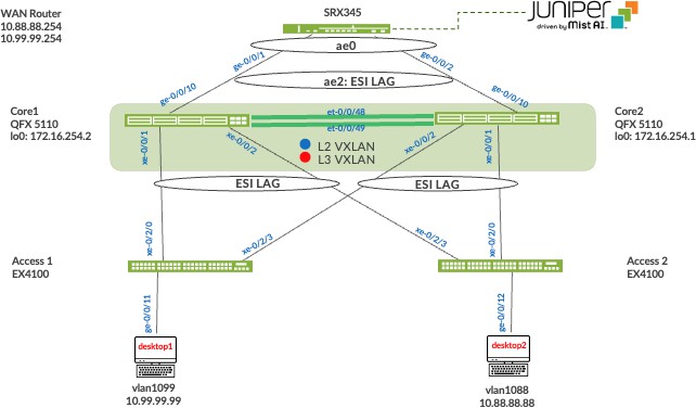
Juniper Mist Wired Assurance provides the template for LAN and loopback IP addressing for each collapsed core device once the device’s management IP address is reachable. Each device is provisioned with a /32 loopback address and /31 point-to-point interfaces that interconnect collapsed core devices within the campus fabric. Devices such as the access layer switches connect to the distribution layer using standard LAGs; while the collapsed core uses ESI-LAGs in a multihoming, load balancing manner.
The WAN router can be provisioned through the portal but is separate from the campus fabric workflow. The WAN router has a southbound LAG configured to connect to the ESI-LAG on the core switches. WAN routers can be standalone or built as a high availability cluster. In this document, a single SRX router is used as the WAN router.
There is a JVD extension available covering more details on WAN router integration especially for production-grade installations. What is shown here is a quick method that has known limits not feasible for production usage.
Create the Campus Fabric
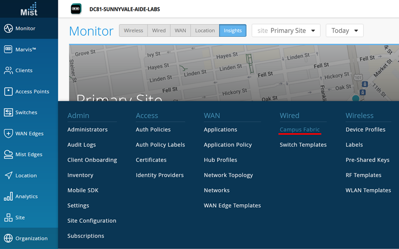
- From Organization on the left-hand side of the portal, select Campus
Fabric.Figure 5: Campus Fabric creation
Mist provides the option of deploying a campus fabric at the organizational or site level noted in the upper-left side of the campus fabric menu shown below. Both designs now enable you to build fabrics with just a single PoD or multiple PoDs based on customer requirements to connect multiple buildings. In EVPN multihoming fabrics, only site-level deployments can be made without PoDs.
In the example shown here, the fabric was built at the site level:
Figure 6: Fabric Site Level Creation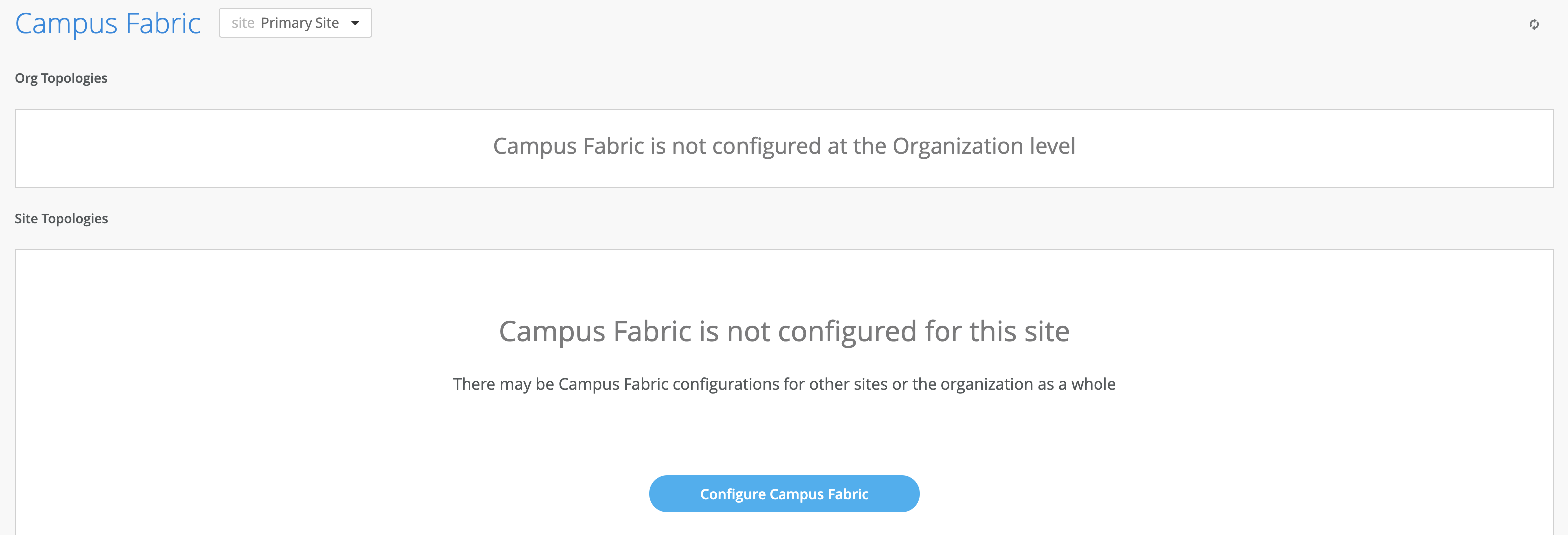
Choose the Campus Fabric Topology
- Select the campus fabric EVPN Multihoming option below:Figure 7: EVPN Multihoming Fabric Creation
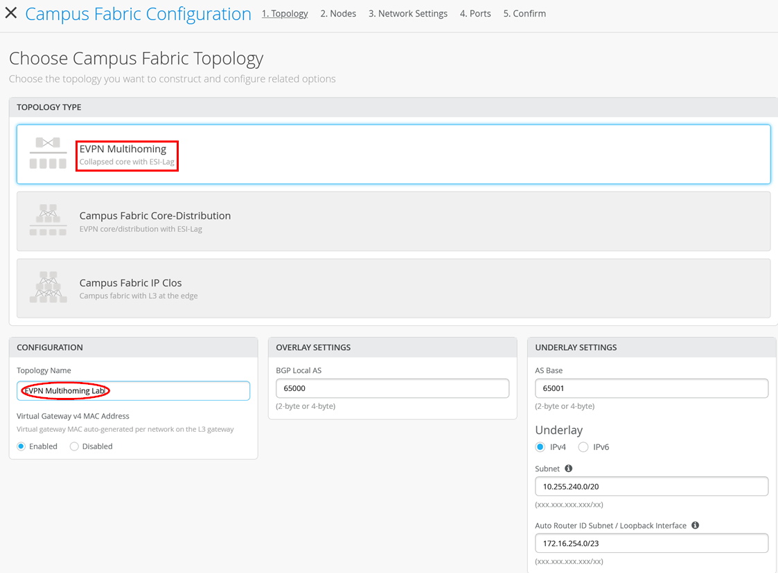
Mist provides a section to name the campus fabric EVPN Multihoming:
- Configuration—Provide a name in accordance with company standards.
- Virtual Gateway v4 MAC Address—Here, you can configure the global MAC address of the gateway used for all VLANs (the assigned default). Or, the MAC address can be unique per VLAN (which is preferred when troubleshooting).
Topology Settings
- BGP Local AS—The BGP AS number used for all control plane interactions.
- AS Base—Represents the starting point of private BGP AS numbers that are automatically allocated per collapsed core device. You can use whatever private BGP AS number range suits your deployment. The routing policy provisioned by Juniper Mist ensures the AS numbers are never advertised outside of the fabric.
- Subnet—Represents the pool of IP addresses used for P2P links between devices. You can use whatever range suits your deployment. Mist breaks this subnet into /31 subnet addressing per link. This number can be modified to suit the specific deployment scale. For example, /24 provides up to 128 P2P /31 subnets.
- Auto Router ID Subnet—Represents the pool of IP addresses associated with each device’s loopback address. Each device will automatically get a loopback IP address of /32 assigned from this pool. You can use whatever range suits your deployment. VXLAN tunnelling using a VTEP is associated with this address. The loopback IP addresses assigned here are only visible in the underlay transport network. The definition of these underlay loopback IP addresses is critical for the operation of the EVPN-VXLAN fabric to function at all.
Note:We recommend default settings for all options unless it conflicts with other networks attached to the campus fabric. The P2P links between each layer utilize /31 addressing to conserve addresses.
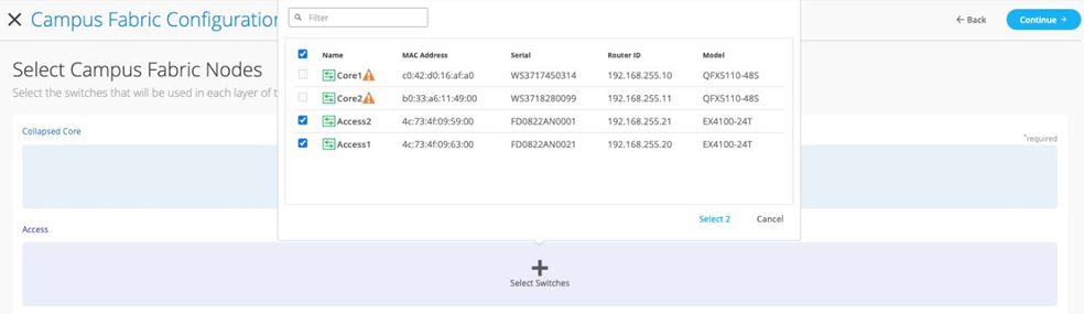
Select Campus Fabric Nodes
Select devices to participate in each layer of the Campus Fabric EVPN Multihoming. We recommend that you validate each device’s presence in the site’s switch inventory prior to the creation of the campus fabric.
The next step is to assign the switches to the layers. Since the switches were named relative to target layer functionality, they can be quickly assigned to their roles.
Figure 8: Select the Fabric Nodes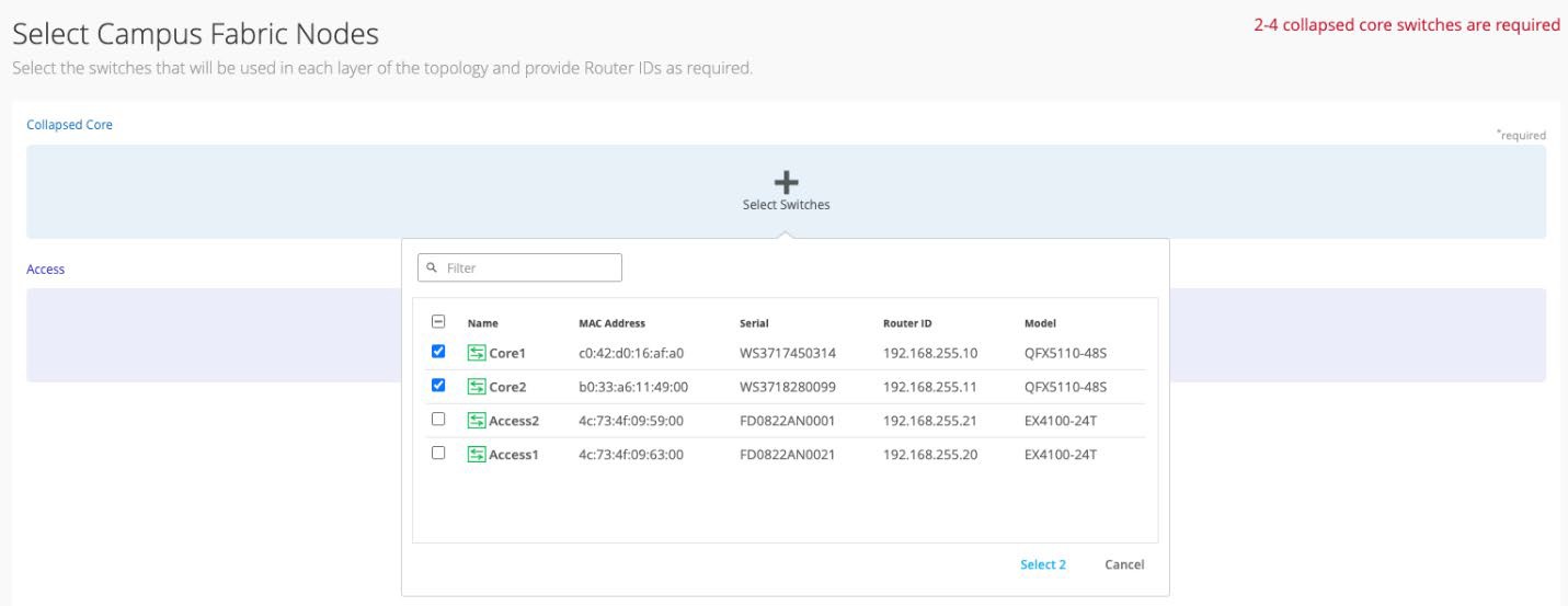
Once all devices have been assigned to the appropriate layers, you must provide an underlay loopback IP address for each device (with the exception of the access switches). This loopback interface is associated with a logical construct called a VTEP; used to source the VXLAN tunnel. The campus fabric EVPN multihoming has VTEPs for VXLAN tunnelling on the collapsed core switches.
When defining an auto router ID subnet prefix, the underlay loopback IP address and router ID assignments happen automatically. There is no need to manually assign them. Make use of this best practice.
Configuring Networks
Enter the network information such as VLANs and VRF options. VLANs are mapped to VNIs and can optionally be mapped to VRFs to provide a way to logically separate traffic such as IoT device traffic from Corp IT traffic.
Figure 9: Configure Networks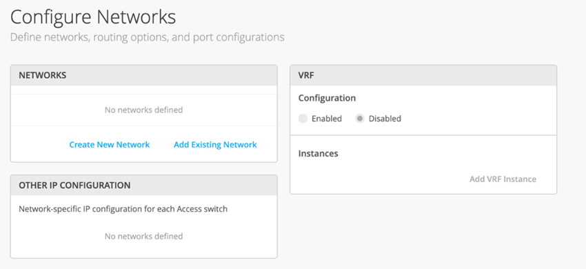
Networks
VLANs can be created or imported under this section including the IP subnet and default gateway per each VLAN.
The Shared Elements section of the campus fabric template includes the networks section mentioned above where VLANs are created.
Figure 10: Networks inherited by Switch Template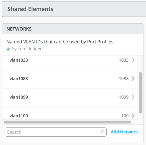
Back to the campus fabric build, select the existing template which includes Layer 2 VLAN information. All VLAN and IP information is inherited from the template.
Figure 11: Network import from Template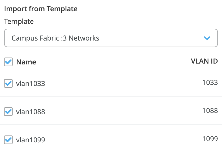
Networks can be edited, newly added, or added from an existing template:
Figure 12: Edit a Network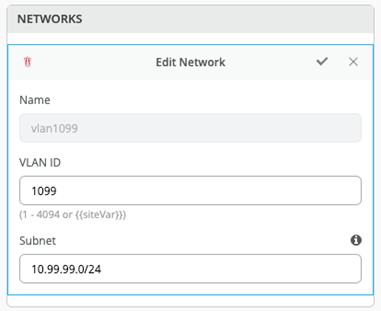
For each network, add the information of the subnet and virtual gateways following the examples below:
Figure 13: Network 1099 and VGA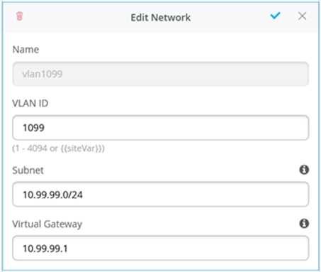 Figure 14: Network 1088 and VGA
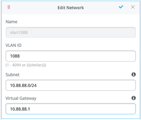 Figure 15: Network 1033 and VGA
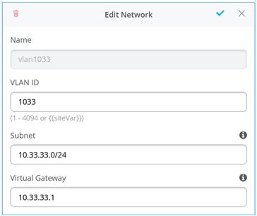
Other IP Configuration
Juniper Mist Wired Assurance provides automatic IP addressing for IRB interfaces for each of the VLANs. Port profiles and port configurations then associate the VLAN with specified ports. In this case, we selected campus fabric EVPN multihoming at the onset of the campus fabric build. This option uses virtual gateway addressing for all devices participating in the Layer 3 subnet. The Core1 and Core2 switches are configured with a shared IP address for each Layer 3 subnet. This address is shared amongst both core switches and acts as the default gateway for all devices within the VLAN. Each core device also receives a unique IP address chosen by Juniper Mist. All addresses can be managed per customer requirements. Juniper Mist assigns IP addresses for Core1 and 2 starting at the beginning of each subnet and the end user can modify these IP addresses accordingly. For example, this deployment uses x.x.x.1 as a default gateway for each VLAN and x.x.x.254 as the gateway of last resort (an MX router in this case) for all traffic leaving the VLAN. Therefore, we modify the IP addresses assigned to Core1 from x.x.x.1 to x.x.x.3 allowing the virtual gateway to use x.x.x.1 for all VLANs.
Figure 16: Core1 Static-IP of Overlay VLAN Used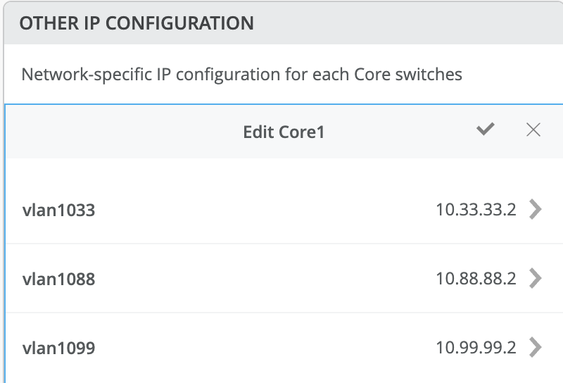 Figure 17: Core2 Static-IP of Overlay VLAN Used
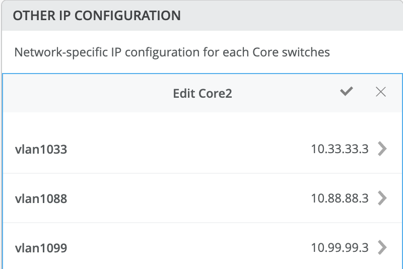
By default, all VLANs are placed in the default VRF. The VRF option allows you to group common VLANs into the same VRF or separate VRFs depending on traffic isolation requirements. This example includes three VRFs or routing instances: corp-it, developers, and guest-wifi.
Here, you build the first corp-it VRF and select the pre-defined vlan 1099.
Figure 18: Enable VRF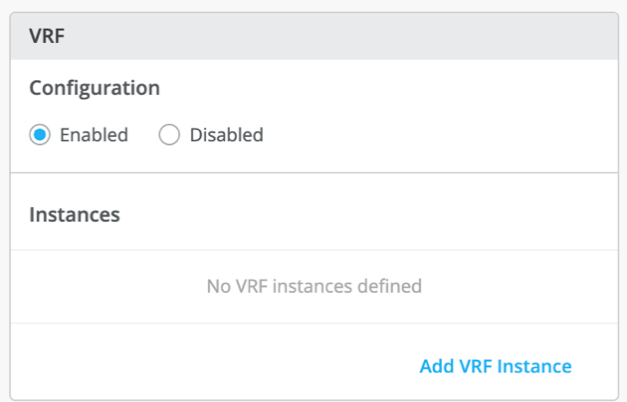 Figure 19: Assign Network to VRF
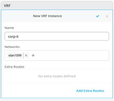
By default, inter-VRF communications are not supported within the campus fabric. If inter-VRF communications is required, each VRF can include extra routes such as a default route that instructs the campus fabric to use an external router or firewall for further security inspection or routing capabilities. In this example, all traffic is trunked over the ESI-LAG and the SRX firewall handles inter-VRF routing. See Figure 11: Topology.
Notice the SRX firewall participates in the VLANs defined within the campus fabric and is the gateway of last resort for all traffic leaving the subnet.
Select the Add Extra Routes option to inform Juniper Mist to forward all traffic leaving 10.99.99.0/24 to use the next hop of the MX router: 10.99.99.254.
Figure 20: Add default route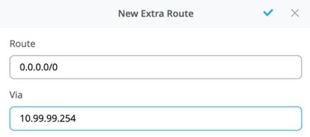
Create two additional VRFs:
- The developers VRF using vlan 1088 with 0.0.0.0/0 utilizing 10.88.88.254
- The guest-wifi VRF using vlan 1033 with 0.0.0.0/0 utilizing 10.33.33.254
Figure 21: Entire Network and VRF Configuration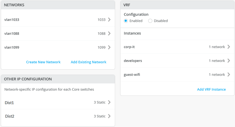
As a next step, you need to provide a name such as “fabric-lag” that the fabric will use to establish the redundant LAG interfaces between all access and collapsed core switches. All created VLANs should be automatically added already as future trunk networks.
Figure 22: Fabric LAG Configuration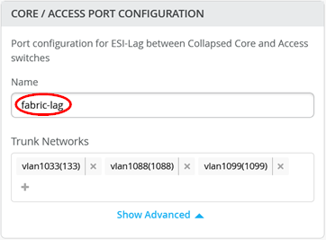
The section configures the active-active ESI-LAG trunks between distribution and access switches. Here, we name the port configuration and include VLANs associated with this configuration. The advanced tab provides additional configuration options:
Figure 23: Fabric LAG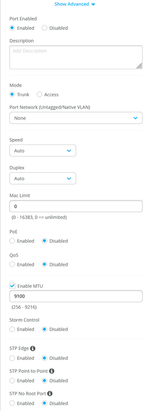 Note:
Note:We recommend default settings unless specific requirements are needed.
Now that all VLANs are configured and assigned to each VRF, and the distribution and access ESI-LAGs have been built, click the Continue button in the upper-right corner of the portal to move to the next step.
Configure Campus Fabric Ports
The final step is the selection of physical ports among core and access switches.
Figure 24: Port Overview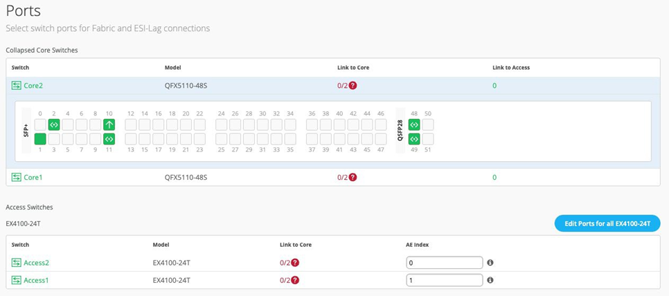 Note:
Note:To ensure accuracy, we recommend that you run the CLI command “show lldp neighbors” on both collapsed core switches prior to this step in the deployment process.
Collapsed Core Switches
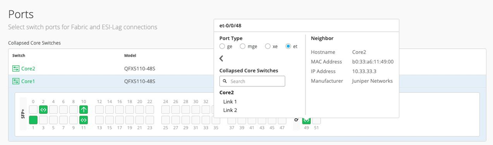
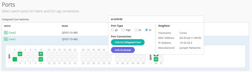
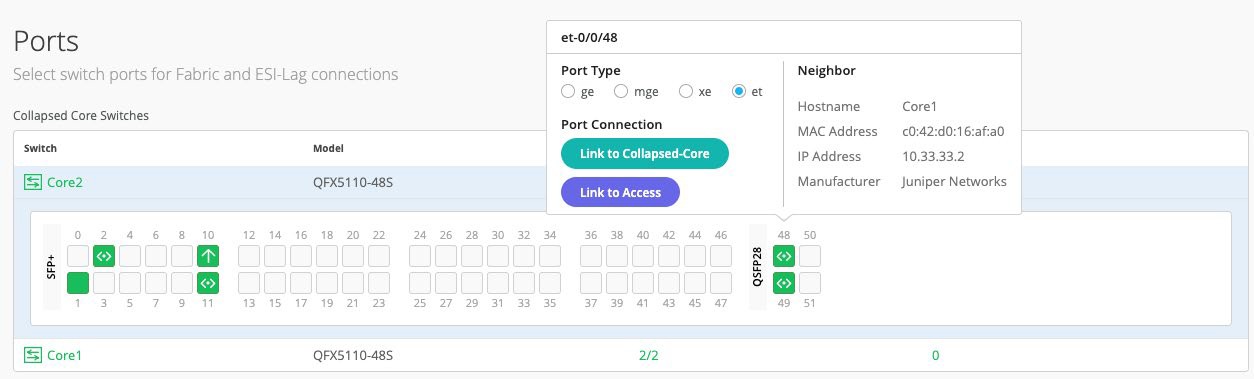
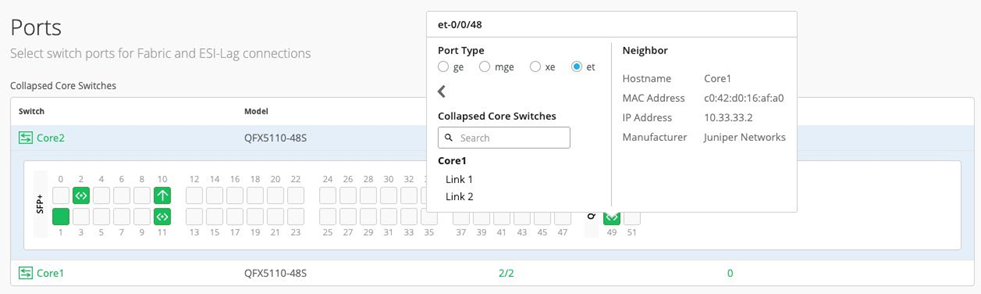
Core1:We are now ready to select the ports that interconnect the collapsed core switches. You must select et-0/0/48 as a Collapsed core link then choose Link1.
Figure 25: First Link core1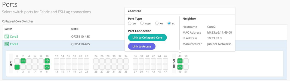
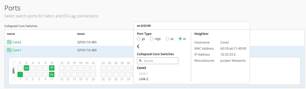
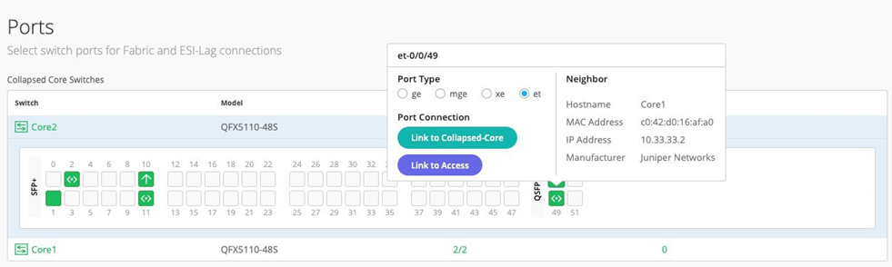
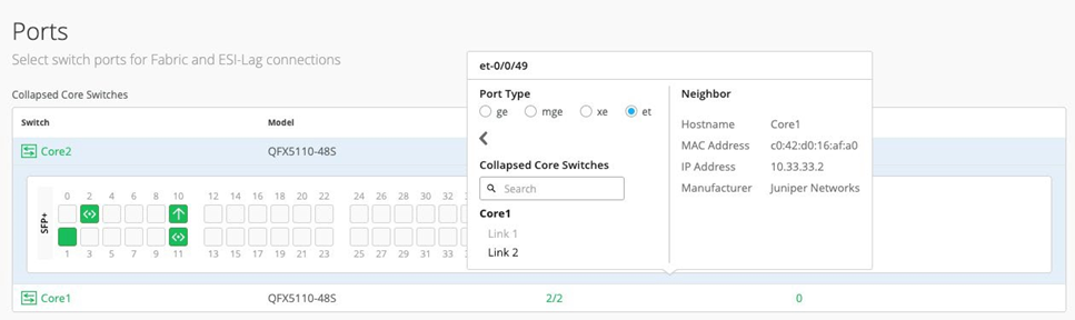
- Core1 second Link. You must select et-0/0/49 as a Collapsed Core link then choose
Link2. Figure 26: Second Link core1
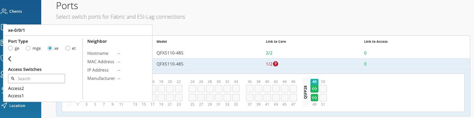
- Core1 first link to Access1. You can select xe-0/0/1 as a link
to Access1.
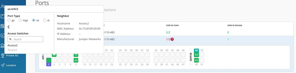
- This is Core1’s second link to Access2. You can select xe-0/0/2 as a link to
Access2.
Core2:
- This is Core2’s first link. You must select et-0/0/48 as a collapsed core link
and then choose Link1.
- This is Core2’s second link. You must select et-0/0/49 as a collapsed core link
and then choose Link2.
- This is Core2’s first link to Access1. You can select xe-0/0/1 as
a link to Access1.
.png)
- This is Core2’s first link to Access2. You can select xe-0/0/2 as
a link to Access2.
.png)
Access Switches
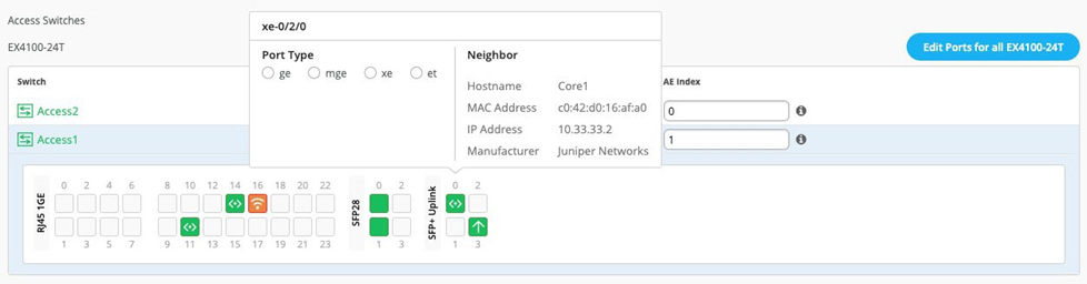
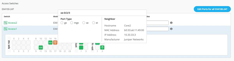
You can now select the ports that interconnect with the collapsed core switches.
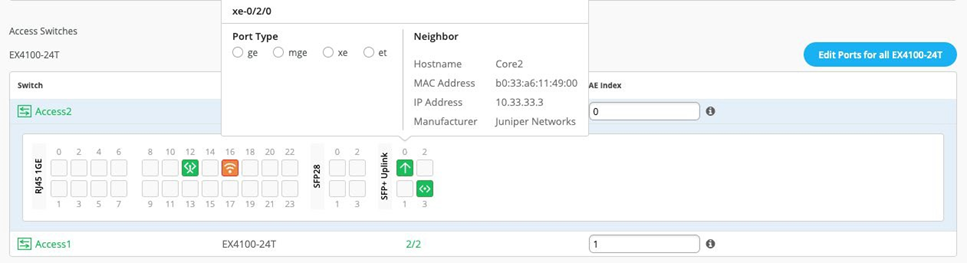
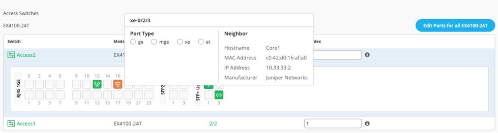
Select both uplinks and interface speed, while allowing Juniper Mist to define each AE index. In this case, uplinks xe-0/2/0, xe-0/2/3 are selected as links to the core on both access switches and AE Index 0/1 (system default numbering) on Access2 and 1 respectively.
Access1:
Access2:
After you select all requisite port combinations, click the Continue button in the upper-right corner of the portal.
Campus Fabric Configuration Confirmation
This last section provides the ability to confirm each device’s configuration as shown below:
Figure 27: Fabric Confirmation View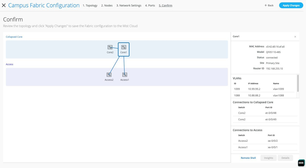 Note:
Note:As we have configured the usage of auto router ID subnet, the underlay loopback IP addresses may still not be assigned on this page, and warnings may appear like the ones shown above. Ignore this for now as the assignments happen when you apply the configuration for the first time.
Once you have completed verification, select the Apply Changes option in the upper-right corner of the portal.
Figure 28: Apply Changes to Fabric
You must complete the second stage confirmation to create the fabric.
Juniper Mist displays the following banner including the estimated time for the campus fabric to be built. The process includes the following:
- Juniper Mist builds the P2P interfaces between distribution and core devices with IP addresses chosen from the range presented at the start of the build.
- Configuring each device with a loopback address from the range presented at the start of the build.
- eBGP is provisioned on each device with unique BGP autonomous system numbers. The primary goal of the underlay is to leverage ECMP for load balancing traffic on a per-packet level for device loopback reachability. The primary goal of the eBGP overlay is for the transport of customer traffic using EVPN-VXLAN.
- Applying IP addresses on each Layer 3 gateway IRB located on Dist1 and Dist2.
- Applying IP addresses on each loopback interface, which is done automatically in this case.
- Configuring routing policies for underlay and overlay connectivity.
- Optimizing MTU settings for P2P underlay, Layer 3 IRB, and ESI-LAG bundles.
- VXLAN-to-VLAN mapping using VNI addresses that are automatically assigned.
- Creating VRFs for corp-it, developers, and guest-wifi and the VLANs associated with each VRF.
- Creating VXLAN tunnels between distribution devices and distribution-core devices (in support of the northbound MX router that is configured in subsequent steps).
- Creating a downloadable connection table (CSV format) that can be used by those involved in the physical buildout of the campus fabric.
- Displaying a graphical interface depicting all devices with BGP peering and the status of physical links.
Figure 29: Applying Changes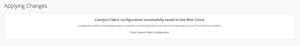
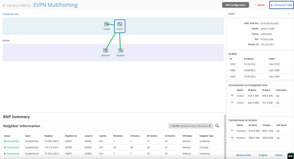
Once you click Close Campus Fabric Configuration, you can view a summary of the newly created campus fabric EVPN multihoming.
Figure 30: Created EVPN Multihoming Fabric View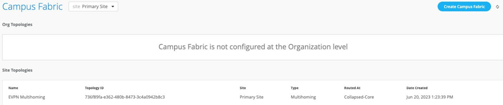
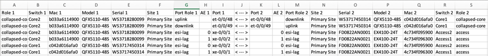
With Juniper Mist Wired Assurance, you can download a connection table (CSV format) representing the physical layout of the campus fabric. This can be used to validate all switch interconnects for those participating in the physical campus fabric build. Once the campus fabric is built or in the process of being built, you can download the connection table.
Connection table spreadsheet:
Apply VLANs to Access Ports
As previously discussed, Juniper Mist provides the ability to templatize well known services such as RADIUS, NTP, DNS, and so on that can be used across all devices within a site. These templates can also include VLANs and port profiles that can be targeted at each device within a site. The last step before verification is to associate VLANs with the requisite ports on each access switch.
In this case, Desktop1 and 2 are associated with different ports on each access switch which requires the configuration to be applied to Access1 and 2, respectively. See Figure 1.
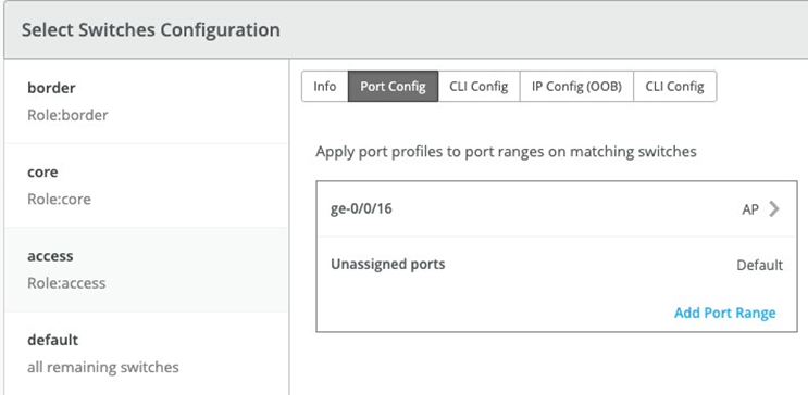
It is also noteworthy that Juniper APs connect to the same port on Access1 and 2, allowing the switch template to be customized with this configuration. For example, the following found under the switch template option is customized to associate each switch with its role: core, distribution, and access. Furthermore, all access switches (defined by the Juniper Networks® EX4400 Switch, as an example) associated the AP port profile named “myaccess” with ge-0/0/16 without needing to configure each switch independently.
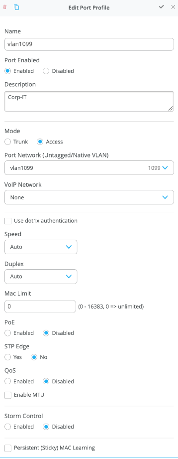
Using Access1 as an example, we apply vlan1099 to port ge-0/0/11 under the Port Config section on Access1. In this example, vlan1099 (corp-it), vlan1088 (developers), and vlan1033 (guest-wifi) are defined in the switch template. Here, vlan1099 is selected under the configuration profile:
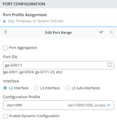
The switch template definition for vlan1099 is shown below, representing attributes associated with VLANs such as dot1x authentication, QoS, and PoE. Vlan1088 and vlan1033 need to be configured in a similar fashion.