APPENDIX: WAN Router Integration into the Fabric
In general, there are several possible ways to attach a WAN router to a campus fabric.
- Using a Layer 2 forwarding method:
- The fabric uplinks are configured as ESI-LAGs and contain one or more tagged VLANs (one for each VRF) to communicate with the WAN router.
- It is also necessary that you configure the IP address of the WAN router interface manually as the next-hop IP address for default-forwarding on each fabric VRF as already shown above.
- The WAN router itself needs to understand standard IEEE 802.3ad LAG with active LACP.
- If you have more than one WAN router attached for redundancy, it is advised to provide failover mechanisms between them for the interface IP addresses towards the fabric. VRRP is recommended.
- Routes between fabric and WAN router are only statically configured.
- Using a Layer 3 forwarding method:
- The fabric uplinks are configured as Layer 3 peer-to-peer IP links.
- Per fabric VRF, a peer-to-peer link needs to be established with the WAN router.
- Usually, there are multiple peer-to-peer links on a single physical uplink. Those are further segmented through tagged VLANs to provide isolation on the uplinks.
- There is no need to manually configure next hops for each VRF inside the fabric as it is assumed that the propagation of the default gateways will be obtained from the WAN router through a routing protocol.
- Between the fabric and the WAN router, a routing protocol must be established to exchange routes.
- The campus fabric supports exterior BGP and OSPF as routing protocols towards the WAN router.
The details of such integration are explained in a JVD extension for all fabric types.
For simplicity, in this JVD we have chosen to utilize the Layer 2 exit through the ESI-LAG as the stretched VLAN, which is not intended to be used in production.
Remember that you chose to deploy the border gateway capability on the Juniper Networks® QFX5110 Switches during the Campus Fabric Core-Distribution deployment, represented below:
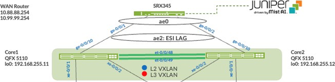
Juniper Mist enables the Juniper Networks® QFX5110 Switch to translate between VXLAN traffic within the campus fabric and standard Ethernet switching for external connectivity. In this case, it is an SRX Series Firewall. Let’s verify the ESI status on the core switches:

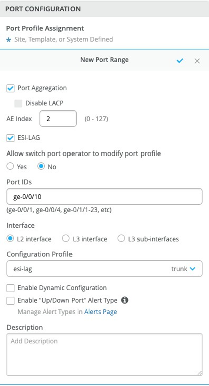
We must configure the ESI-LAG for Layer 2 connectivity between the collapsed core switches and the WAN Router as Juniper Mist does not configure this automatically. You can associate a pre-defined port profile with the requisite ports on each core switch.
The following represents an existing port profile applied to each SRX Series Firewall facing the QFX5110 Switch port:
Save the configuration and then verify the changes on the core switch.
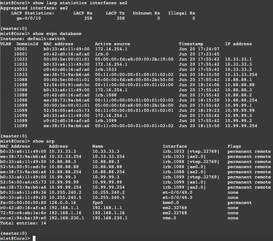
Core1: The active status of LACP to the WAN router produces new entries in the switch’s ARP tables:
Core2: The active status of LACP to the WAN router produces new entries in the switch’s ARP tables:
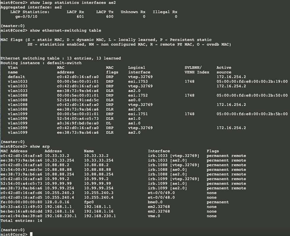
The IP address entries with 254 in the last octet now found in Core1 and Core2 are the WAN router’s default gateway addresses.
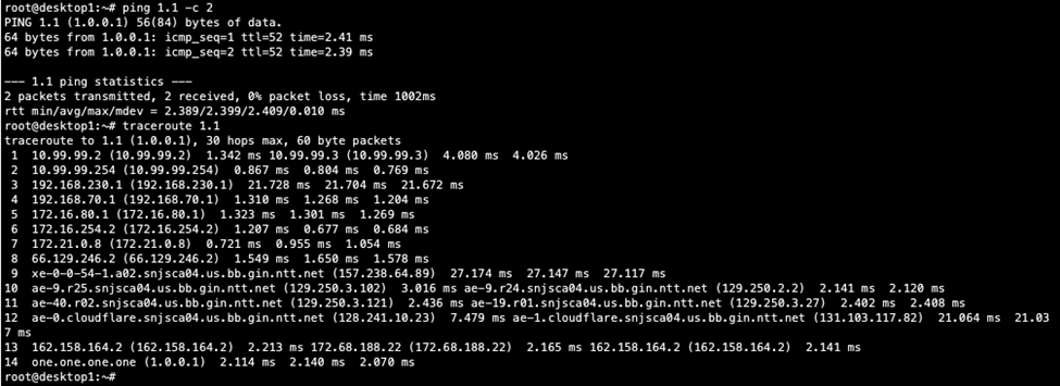
We go back to Desktop1 to see if it can traverse the fabric:
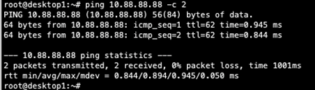
Next, verify that Desktop1 can ping Desktop2:
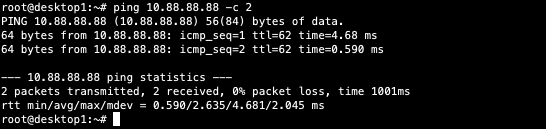
As the last step, verify Desktop1 can ping Desktop2:
.jpeg)
Conclusion: Connectivity within and outside of the campus fabric is verified. Desktops communicate with each other through the fabric, each in an isolated VRF, then forwarded to the SRX Series Firewall through the ESI-LAG on both core devices when accessing services outside of the campus fabric. The campus fabric performs total isolation between the VRFs by default while using the SRX Series Firewall to accept or discard inter-VRF communications.