For
a control-plane driven overlay, there must be a signalling path between
the VXLAN virtual tunnel endpoint (VTEP) devices.
In this reference design with an IPv4 Fabric underlay, all overlay
types use IBGP with Multiprotocol BGP (MP-IBGP) to maintain the signalling
path between the VTEPs within an autonomous system. The spine devices
act as a route reflector cluster, and the leaf devices are route reflector
clients, as shown in Figure 1.
Figure 1: IBGP Route Reflector Cluster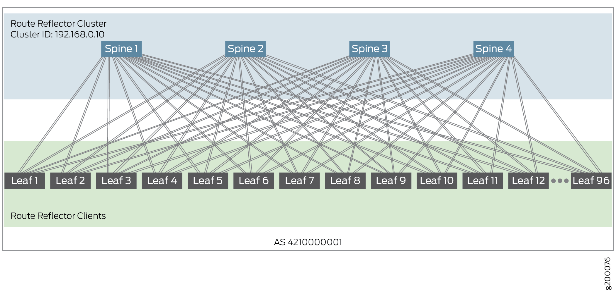
To configure an EVPN-VXLAN data center fabric architecture with
an IPv6 Fabric, see IPv6 Fabric Underlay
and Overlay Network Design and Implementation with EBGP instead of this procedure. In an IPv6 Fabric configuration, we use
EBGP and IPv6 for underlay connectivity, as well as EBGP and IPv6
for peering and EVPN signalling in the overlay. With an IPv6 Fabric,
the VTEPs encapsulate the VXLAN packets with an IPv6 outer header
and tunnel the packets using IPv6. You can use either an IPv4 Fabric
or an IPv6 Fabric in your data center architecture. You can’t
mix IPv4 Fabric and IPv6 Fabric elements in the same architecture.
To configure IBGP for the overlay peering in an IPv4
Fabric, perform the following:
- Configure an AS number for overlay
IBGP. All leaf and spine devices participating in the overlay use
the same AS number. In this example, the AS number is private AS 4210000001.
Spine and Leaf Devices:
set routing-options autonomous-system 4210000001
- Configure IBGP using EVPN signaling
on each spine device to peer with every leaf device (Leaf 1 through
Leaf 96). Also, form the route reflector cluster (cluster ID 192.168.0.10)
and configure equal cost multipath (ECMP) for BGP. The configuration
included here belongs to Spine 1, as shown in Figure 2.
Figure 2: IBGP – Spine Device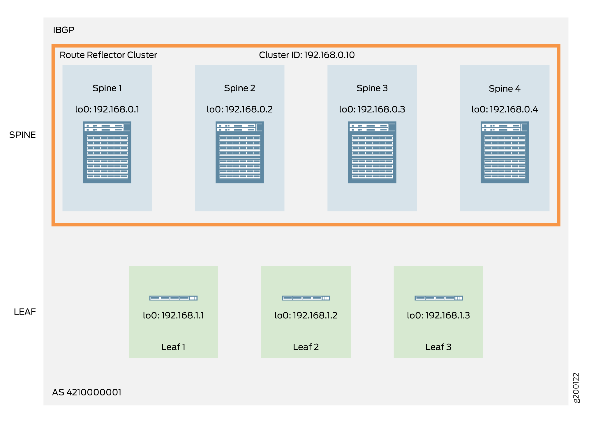
Tip: By default, BGP selects only one best path when there are
multiple, equal-cost BGP paths to a destination. When you enable BGP
multipath by including the multipath statement at the [edit protocols bgp group group-name] hierarchy
level, the device installs all of the equal-cost BGP paths into the
forwarding table. This feature helps load balance the traffic across
multiple paths.
Spine 1:
set protocols bgp group OVERLAY type internal
set protocols bgp group OVERLAY local-address 192.168.0.1
set protocols bgp group OVERLAY family evpn signaling
set protocols bgp group OVERLAY cluster 192.168.0.10
set protocols bgp group OVERLAY multipath
set protocols bgp group OVERLAY neighbor 192.168.1.1
...
set protocols bgp group OVERLAY neighbor 192.168.1.96
- Configure IBGP on the spine devices to peer with all the
other spine devices acting as route reflectors. This step completes
the full mesh peering topology required to form a route reflector
cluster.
Spine 1:
set protocols bgp group  OVERLAY_RR_MESH type internal
set protocols bgp group  OVERLAY_RR_MESH local-address 192.168.0.1
set protocols bgp group  OVERLAY_RR_MESH family evpn signaling
set protocols bgp group  OVERLAY_RR_MESH neighbor 192.168.0.2
set protocols bgp group  OVERLAY_RR_MESH neighbor 192.168.0.3
set protocols bgp group  OVERLAY_RR_MESH neighbor 192.168.0.4
- Configure BFD on all BGP groups on the spine devices to
enable rapid detection of failures and reconvergence.
Spine 1:
set protocols bgp group OVERLAY bfd-liveness-detection minimum-interval 350
set protocols bgp group OVERLAY bfd-liveness-detection multiplier 3
set protocols bgp group OVERLAY bfd-liveness-detection session-mode automatic
set protocols bgp group  OVERLAY_RR_MESH bfd-liveness-detection minimum-interval 350
set protocols bgp group  OVERLAY_RR_MESH bfd-liveness-detection multiplier 3
set protocols bgp group  OVERLAY_RR_MESH bfd-liveness-detection session-mode automatic
- Configure IBGP with EVPN signaling from each leaf device
(route reflector client) to each spine device (route reflector cluster). The
configuration included here belongs to Leaf 1, as shown in Figure 3.
Figure 3: IBGP – Leaf Device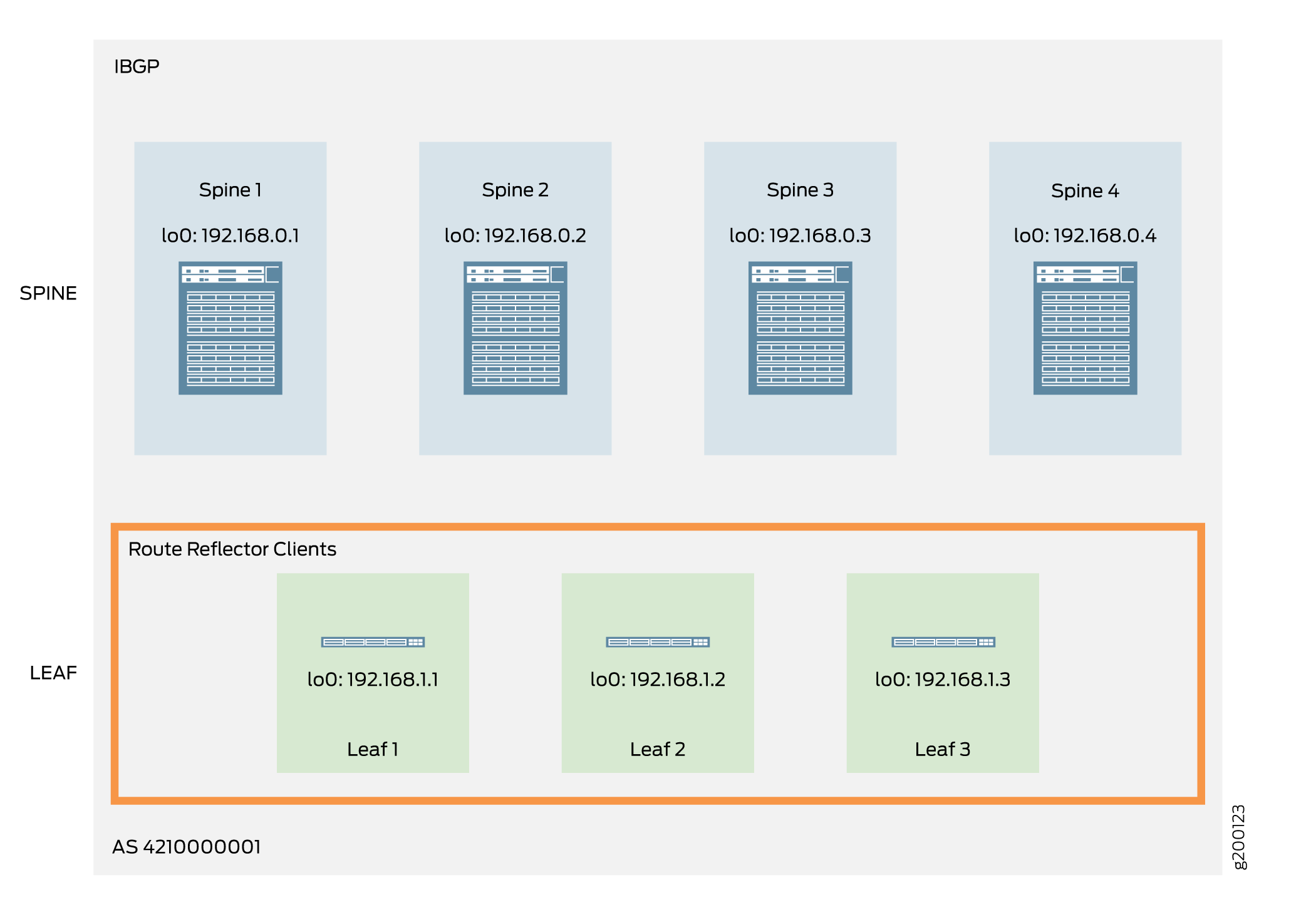
Leaf 1:
set protocols bgp group OVERLAY type internal
set protocols bgp group OVERLAY local-address 192.168.1.1
set protocols bgp group OVERLAY family evpn signaling
set protocols bgp group OVERLAY neighbor 192.168.0.1
set protocols bgp group OVERLAY neighbor 192.168.0.2
set protocols bgp group OVERLAY neighbor 192.168.0.3
set protocols bgp group OVERLAY neighbor 192.168.0.4
- Configure BFD on the leaf devices to enable rapid detection
of failures and reconvergence.
Note: QFX5100 switches only support BFD liveness detection minimum
intervals of 1 second or longer. The configuration here has a minimum
interval of 350 ms, which is supported on devices other than QFX5100
switches.
Leaf 1:
set protocols bgp group OVERLAY bfd-liveness-detection minimum-interval 350
set protocols bgp group OVERLAY bfd-liveness-detection multiplier 3
set protocols bgp group OVERLAY bfd-liveness-detection session-mode automatic
- Verify that IBGP is functional on the spine devices.
user@spine-1> show bgp summary
Groups: 5 Peers: 221 Down peers: 0
Table          Tot Paths  Act Paths Suppressed    History Damp State    Pending
inet.0
                    9711        182          0          0          0          0
inet6.0
                       0          0          0          0          0          0
bgp.evpn.0
                   31520      31520          0          0          0          0
Peer                     AS      InPkt     OutPkt    OutQ   Flaps Last Up/Dwn State|#Active/Received/Accepted/Damped...
192.168.0.2       421000001      28724      31106       0       0    22:40:41 Establ
  bgp.evpn.0: 8227/8227/8227/0
 default-switch.evpn.0: 54/54/54/0...

192.168.1.96      421000001       4831      73047       0       0    22:43:41 Establ
  bgp.evpn.0: 1549/1549/1549/0
  default-switch.evpn.0: 11/11/11/0
  __default_evpn__.evpn.0: 1471/1471/1471/0
---(more)---
- Verify that BFD is operational on the spine devices.
user@spine-1> show bfd session
                                                  Detect   Transmit
Address                  State     Interface      Time     Interval  Multiplier
192.168.0.2              Up                       1.050     0.350        3
192.168.0.3              Up                       1.050     0.350        3
192.168.0.4              Up                       1.050     0.350        3
192.168.1.1              Up                       1.050     0.350        3
...
192.168.1.96             Up                       1.050     0.350        3
- Verify that IBGP is operational
on the leaf devices.
user@leaf-1> show bgp summary
Groups: 2 Peers: 8 Down peers: 0
Table          Tot Paths  Act Paths Suppressed    History Damp State    Pending
inet.0
                     834        233          0          0          0          0
bgp.evpn.0
                    3193        833          0          0          0          0
Peer                     AS      InPkt     OutPkt    OutQ   Flaps Last Up/Dwn State|#Active/Received/Accepted/Damped...
## IBGP Overlay
	192.168.0.1      4210000001       9371        596       0       2     4:17:03 Establ
  bgp.evpn.0: 706/829/829/0
  default-switch.evpn.0: 701/824/824/0
  __default_evpn__.evpn.0: 5/5/5/0
192.168.0.2      4210000001      10175        579       0       2     4:16:35 Establ
  bgp.evpn.0: 43/834/834/0
  default-switch.evpn.0: 43/829/829/0
  __default_evpn__.evpn.0: 0/5/5/0
192.168.0.3      4210000001      10463        621       0       2     4:34:55 Establ
  bgp.evpn.0: 43/834/834/0
  default-switch.evpn.0: 43/829/829/0
  __default_evpn__.evpn.0: 0/5/5/0
192.168.0.4      4210000001       8250        463       0       1     3:12:47 Establ
  bgp.evpn.0: 41/696/696/0
  default-switch.evpn.0: 41/691/691/0
  __default_evpn__.evpn.0: 0/5/5/0
- Verify that BFD is operational on the leaf devices.
user@leaf-10> show bfd session
                                                  Detect   Transmit
Address                  State     Interface      Time     Interval  Multiplier
192.168.0.1              Up                       1.050     0.350        3
192.168.0.2              Up                       1.050     0.350        3
192.168.0.3              Up                       1.050     0.350        3
192.168.0.4              Up                       1.050     0.350        3