Static VXLAN Tunnels with Q-in-Q
For small MC-LAG networks, you can use static VXLAN to reduce the control plane complexity in your network. Configuring VTEPs on a static VXLAN is straightforward. Use this example to configure static VXLAN tunnels with Q-in-Q tagging (VLAN translation) between data centers. In this example, we focus on the following features:
-
Static VXLAN—Static VXLAN connects servers in different data centers by creating a Layer 2 path (tunnel). For more information about static VXLAN, see Static VXLAN.
-
Q-in-Q tunnels—Q-in-Q tunnels segregates and bundles different customer VLAN (C-VLAN) traffic into a single service provider VLAN.
For more information about Q-in-Q tunnels, see Configuring Q-in-Q Tunneling and VLAN Q-in-Q Tunneling and VLAN Translation.
-
MC-LAG—MC LAG provides redundancy and load balancing. We configure ICL and ICCP connection between two peer devices to create the MC-LAG. For more information about MC-LAG, see Understanding Multichassis Link Aggregation Groups
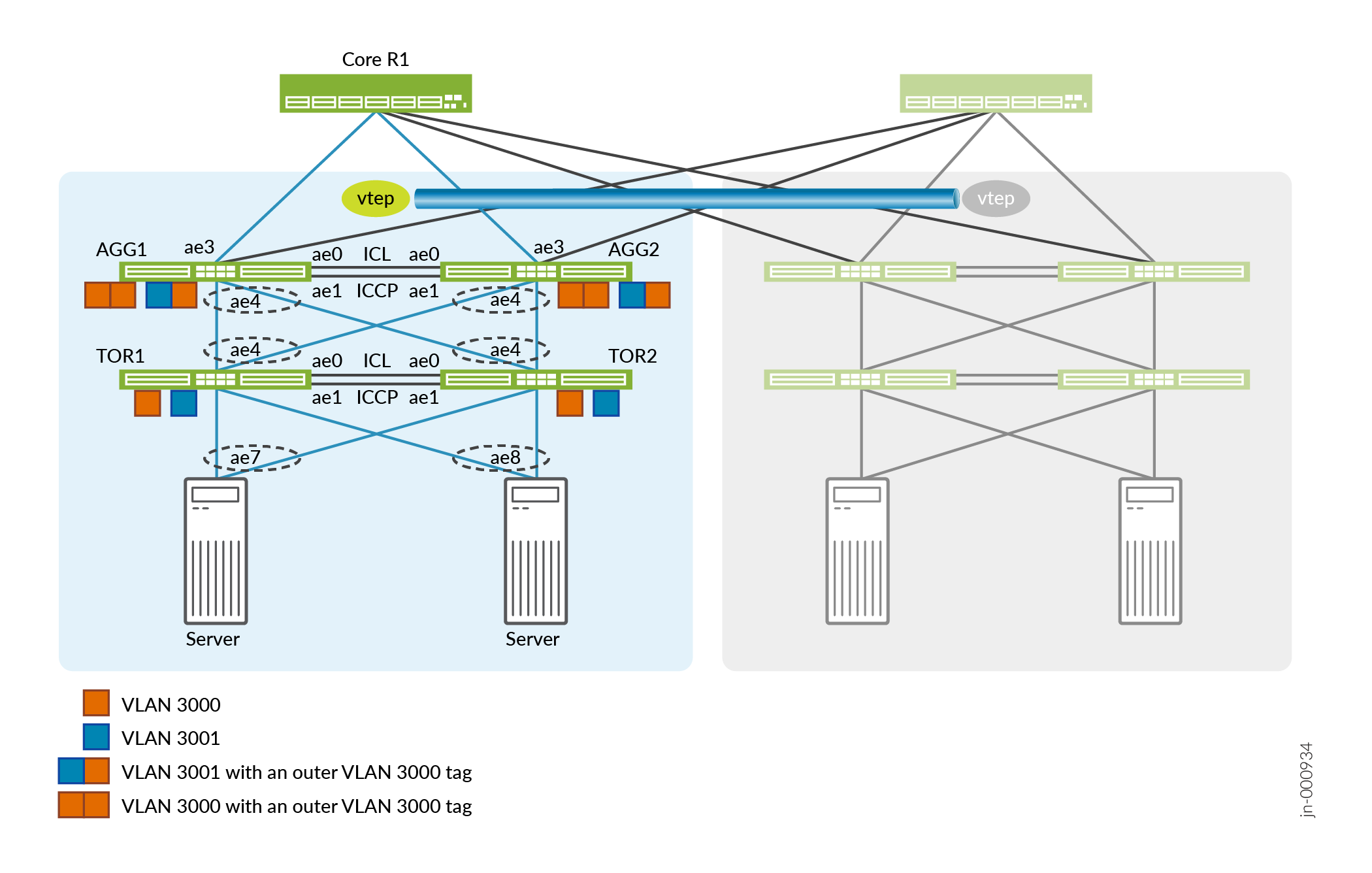
Figure 1 shows a portion of a spine-leaf data center (POD). Within the POD, the TOR devices (TOR1 and TOR2) collect VLANs from the servers below and also manages the VLAN translations (Q-in-Q tunnels). The aggregators collect VLANs from different TOR devices and function as the gateway for the POD. We use a static VXLAN tunnel as a gateway between two PODs. We configure MC-LAG between the peer TOR devices and the peer aggregators. In our reference test environment, we tested a configuration with 64 pods. For this example, we describe how to configure the aggregators and TOR devices in a single pod.
This example is configured on top of an existing IP Fabric. See IP Fabric Underlay Network Design and Implementation.
Configuring the Aggregators
The following section describes how to configure the aggregators.
-
Configure the aggregators to support aggregated Ethernet and MC-LAG.
-
Set the maximum number of aggregated Ethernet interfaces.
-
Set the service identifier (SID) for the LAG.
-
Configure a loopback address.
-
Configure a management port. We use the management interface as an "always up" port to support the keepalive communication between ICCP peers.
AGG1 and AGG2
set chassis aggregated-devices ethernet device-count 64
set switch-options service-id 1
AGG1
set interfaces lo0 unit 0 family inet address 192.168.1.4/32 primary
set interfaces em0 unit 0 family inet address 10.48.49.69/221
AGG2
set interfaces lo0 unit 0 family inet address 192.168.1.5/32 primary
set nterfaces em0 unit 0 family inet address 10.48.49.117/22
-
-
Assign the aggregated Ethernet interfaces.
-
ae0 and ae1 forms the ICL and ICCP links between the aggregators.
-
ae3 connects the aggregator to the spine devices.
-
ae4 connects the aggregators to the TOR devices.
AGG1 and AGG2
set interfaces xe-0/0/49:0 ether-options 802.3ad ae0
set interfaces xe-0/0/49:1 ether-options 802.3ad ae1
set interfaces xe-0/0/48:0 ether-options 802.3ad ae3
set interfaces xe-0/0/50:0 ether-options 802.3ad ae4
set interfaces xe-0/0/50:1 ether-options 802.3ad ae4
-
-
Enable LACP on the aggregated Ethernet interfaces. Enable LACP with the
fast periodic interval to send a packet every second.
AGG1 and AGG2
set interfaces ae4 aggregated-ether-options minimum-links 1
set interfaces ae4 aggregated-ether-options lacp active
set interfaces ae4 aggregated-ether-options lacp periodic fast
set interfaces ae4 aggregated-ether-options lacp system-id 00:00:00:00:04:01
set interfaces ae4 aggregated-ether-options lacp admin-key 4
-
Configure the MC-LAG interfaces from the aggregators to the TOR devices and
set it to active-active mode. Set a unique chassis ID for each peer.
AGG1 and AGG2
set interfaces ae4 aggregated-ether-options mc-ae mc-ae-id 4
set interfaces ae4 aggregated-ether-options mc-ae redundancy-group 1
set interfaces ae4 aggregated-ether-options mc-ae mode active-active
set interfaces ae4 aggregated-ether-options mc-ae status-control active
set interfaces ae4 aggregated-ether-options mc-ae init-delay-time 300
AGG1
set interfaces ae4 aggregated-ether-options mc-ae chassis-id 0
AGG2
set interfaces ae4 aggregated-ether-options mc-ae chassis-id 1
-
Configure the ICCP peers (AGG1 and AGG2) across the ICL. We use the IP
address of the management link when we configure
backup-liveness-detectionto exchange keepalive messages.AGG1
set interfaces ae0 description "ICCP link Connected to MCLAG peer"
set interfaces ae0 unit 0 family inet address 172.16.10.1/30
set multi-chassis multi-chassis-protection 172.16.10.2 interface ae1
set protocols iccp local-ip-addr 172.16.10.1
set protocols iccp peer 172.16.10.2 session-establishment-hold-time 600
set protocols iccp peer 172.16.10.2 redundancy-group-id-list 1
set protocols iccp peer 172.16.10.2 backup-liveness-detection backup-peer-ip 10.48.49.69
set protocols iccp peer 172.16.10.2 liveness-detection minimum-interval 1000
AGG2
set interfaces ae0 description "ICCP link Connected to MCLAG peer"
set interfaces ae0 unit 0 family inet address 172.16.10.2/30
set multi-chassis multi-chassis-protection 172.16.10.1 interface ae1
set protocols iccp local-ip-addr 172.16.10.2
set protocols iccp peer 172.16.10.1 session-establishment-hold-time 600
set protocols iccp peer 172.16.10.1 redundancy-group-id-list 1
set protocols iccp peer 172.16.10.1 backup-liveness-detection backup-peer-ip 10.48.49.117
set protocols iccp peer 172.16.10.1 liveness-detection minimum-interval 1000
-
Configure the interfaces to support VLANs.
AGG1 and AGG2
set vlans SP-VLAN-3000 vlan-id 3000
set vlans SP-VLAN-3000 interface ae1.3000
set vlans SP-VLAN-3000 interface ae4.3000
set vlans SP-VLAN-3001 vlan-id 3001
set vlans SP-VLAN-3001 interface ae1.3001
set vlans SP-VLAN-3001 interface ae4.3001

set interfaces ae1 unit 3000 encapsulation vlan-bridge
set interfaces ae1 unit 3000 vlan-id 3000
set interfaces ae1 unit 3001 encapsulation vlan-bridge
set interfaces ae1 unit 3001 vlan-id 3001

set interfaces ae4 description "Connected to TOR1 TOR2"
set interfaces ae4 flexible-vlan-tagging
set interfaces ae4 encapsulation flexible-ethernet-services

set interfaces ae4 unit 3000 encapsulation vlan-bridge
set interfaces ae4 unit 3000 vlan-id 3000
set interfaces ae4 unit 3001 encapsulation vlan-bridge
set interfaces ae4 unit 3001 vlan-id 3001
-
Configure the interface to the Spine devices.
AGG1
set interfaces ae3 description "Connected to Spine-1"
set interfaces ae3 unit 0 family inet address 192.168.100.2/24
AGG2
set interfaces ae3 description "Connected to Spine-1"
set interfaces ae3 unit 0 family inet address 192.168.200.2/24
-
Enable static VXLAN by configuring the local and remote VTEP
interfaces.
AGG1 and AGG2
set switch-options vtep-source-interface lo0.0
set switch-options remote-vtep-list 192.168.1.6
-
Map the VLANs to the remote VTEP.
AGG1 and AGG2
set vlans SP-VLAN-3000 vxlan vni 103000
set vlans SP-VLAN-3000 vxlan ingress-node-replication
set vlans SP-VLAN-3000 vxlan static-remote-vtep-list 192.168.1.6
set vlans SP-VLAN-3001 vxlan vni 103001
set vlans SP-VLAN-3001 vxlan ingress-node-replication
set vlans SP-VLAN-3001 vxlan static-remote-vtep-list 192.168.1.6
Configuring the TOR Devices
The following section describes how to configure the TOR devices.
-
Configure the TOR device to support aggregated Ethernet and MC-LAG.
-
Set the maximum number of aggregated Ethernet interfaces.
-
Set the SID for the LAG.
-
Configure a loopback address.
-
Configure a management port. We use the management interface as an "always up" port to support the keepalive communication between ICCP peers.
TOR1 and TOR2
set chassis aggregated-devices ethernet device-count 64
set switch-options service-id 1
TOR1
set interfaces lo0 unit 0 family inet address 192.168.1.8/32 primary
set interfaces em0 unit 0 family inet address 10.48.49.197/22
TOR2
set interfaces lo0 unit 0 family inet address 192.168.1.9/32 primary
set interfaces em0 unit 0 family inet address 10.48.49.196/22
-
-
Assign the aggregated Ethernet interfaces.
-
ae0 and ae1 form the ICL and ICCP link between the TOR devices.
-
ae4 connects the TOR devices to the aggregators.
-
ae7 and ae8 connect the TOR devices to the servers.
TOR1 and TOR2
set interfaces xe-0/0/0:0 ether-options 802.3ad ae0
set interfaces xe-0/0/0:1 ether-options 802.3ad ae0
set interfaces xe-0/0/0:2 ether-options 802.3ad ae1
set interfaces xe-0/0/0:3 ether-options 802.3ad ae1
set interfaces xe-0/0/1:0 ether-options 802.3ad ae4
set interfaces xe-0/0/1:1 ether-options 802.3ad ae4
set interfaces xe-0/0/2:1 ether-options 802.3ad ae7
set interfaces xe-0/0/2:3 ether-options 802.3ad ae8
-
-
Enable LACP on the aggregated Ethernet interfaces. Enable LACP with a fast
periodic interval to send a packet every second.
TOR1 and TOR2
set interfaces ae4 aggregated-ether-options minimum-links 1
set interfaces ae4 aggregated-ether-options lacp active
set interfaces ae4 aggregated-ether-options lacp periodic fast
set interfaces ae4 aggregated-ether-options lacp system-id 00:00:00:00:04:02
set interfaces ae4 aggregated-ether-options lacp admin-key 4

set interfaces ae7 aggregated-ether-options minimum-links 1
set interfaces ae7 aggregated-ether-options lacp active
set interfaces ae7 aggregated-ether-options lacp periodic fast
set interfaces ae7 aggregated-ether-options lacp system-id 00:00:00:00:07:01
set interfaces ae7 aggregated-ether-options lacp admin-key 7

set interfaces ae8 aggregated-ether-options minimum-links 1
set interfaces ae8 aggregated-ether-options lacp active
set interfaces ae8 aggregated-ether-options lacp periodic fast
set interfaces ae8 aggregated-ether-options lacp system-id 00:00:00:00:08:01
set interfaces ae8 aggregated-ether-options lacp admin-key 8
-
Configure the interfaces to support VLANs and Q-in-Q translation.
Note:
When you configure Q-in-Q mapping, the device selects the lowest value in the VLAN ID range as the outer tag. For example, with a range of 3000-3001 in our vlan-id-list, our device uses the VLAN 3000 as the outer tag. When the device receives an outgoing packet with a VLAN in the 3000 to 3001 range, the device pushes an outer tag of with a VLAN ID of 3000. Conversely, the device strips the outer tag for incoming packets with a VLAN ID of 3000 in its outer tag.
TOR1 and TOR2
set interfaces ae1 description "ICL link Connected to MCLAG peer"
set interfaces ae1 flexible-vlan-tagging
set interfaces ae1 encapsulation encapsulation extended-vlan-bridge
set interfaces ae1 unit 3000 vlan-id 3000

set interfaces ae4 description "Connected to AGG1 AGG2"
set interfaces ae4 flexible-vlan-tagging
set interfaces ae4 encapsulation extended-vlan-bridge
set interfaces ae4 unit 3000 vlan-id-list 3000-3001
set interfaces ae4 unit 3000 input-vlan-map push
set interfaces ae4 unit 3000 output-vlan-map pop

set interfaces ae7 description "Connected to Server1"
set interfaces ae7 flexible-vlan-tagging
set interfaces ae7 encapsulation extended-vlan-bridge
set interfaces ae7 unit 3000 vlan-id-list 3000-3001
set interfaces ae7 unit 3000 input-vlan-map push
set interfaces ae7 unit 3000 output-vlan-map pop

set interfaces ae8 description "Connected to Server2"
set interfaces ae8 flexible-vlan-tagging
set interfaces ae8 encapsulation extended-vlan-bridge
set interfaces ae8 unit 3000 vlan-id-list 3000-3001
set interfaces ae8 unit 3000 input-vlan-map push
set interfaces ae8 unit 3000 output-vlan-map pop

set vlans SP-VLAN-3000 interface ae1.3000
set vlans SP-VLAN-3000 interface ae4.3000
set vlans SP-VLAN-3000 interface ae7.3000
set vlans SP-VLAN-3000 interface ae8.3000
set vlans SP-VLAN-3000 service-id 3000
set vlans SP-VLAN-3001 interface ae4.3001
set vlans SP-VLAN-3001 interface ae7.3001
set vlans SP-VLAN-3001 interface ae8.3001
set vlans SP-VLAN-3001 service-id 3001
-
Configure the MC-LAG interfaces from the TOR devices to the aggregators and
servers and set it to active-active mode. Set a unique chassis ID for each
peer.
TOR1 and TOR2
set interfaces ae4 aggregated-ether-options mc-ae mc-ae-id 4
set interfaces ae4 aggregated-ether-options mc-ae redundancy-group 1
set interfaces ae4 aggregated-ether-options mc-ae mode active-active
set interfaces ae4 aggregated-ether-options mc-ae status-control active
set interfaces ae4 aggregated-ether-options mc-ae init-delay-time 300

set interfaces ae7 aggregated-ether-options mc-ae mc-ae-id 7
set interfaces ae7 aggregated-ether-options mc-ae redundancy-group 1
set interfaces ae7 aggregated-ether-options mc-ae mode active-active
set interfaces ae7 aggregated-ether-options mc-ae status-control active
set interfaces ae7 aggregated-ether-options mc-ae init-delay-time 300

set interfaces ae8 aggregated-ether-options mc-ae mc-ae-id 8
set interfaces ae8 aggregated-ether-options mc-ae redundancy-group 1
set interfaces ae8 aggregated-ether-options mc-ae mode active-active
set interfaces ae8 aggregated-ether-options mc-ae status-control active
set interfaces ae8 aggregated-ether-options mc-ae init-delay-time 300
TOR1
set interfaces ae4 aggregated-ether-options mc-ae chassis-id 0
set interfaces ae7 aggregated-ether-options mc-ae chassis-id 0
set interfaces ae8 aggregated-ether-options mc-ae chassis-id 0
TOR2
set interfaces ae4 aggregated-ether-options mc-ae chassis-id 1
set interfaces ae7 aggregated-ether-options mc-ae chassis-id 1
set interfaces ae8 aggregated-ether-options mc-ae chassis-id 1
-
Configure ICCP across the ICL between the two TOR peers (TOR1 and TOR2). We
use the IP address of the management link when we configure
backup-liveness-detectionto exchange keepalive messages.TOR1
set interfaces ae0 description "ICCP link Connected to MCLAG peer"
set interfaces ae0 unit 0 family inet address 172.16.20.1/30
set multi-chassis multi-chassis-protection 172.16.20.2 interface ae1
set protocols iccp local-ip-addr 172.16.2.1
set protocols iccp peer 172.16.20.2 session-establishment-hold-time 600
set protocols iccp peer 172.16.20.2 redundancy-group-id-list 1
set protocols iccp peer 172.16.20.2 backup-liveness-detection backup-peer-ip 10.48.49.197
set protocols iccp peer 172.16.20.2 liveness-detection minimum-interval 1000
TOR2
set interfaces ae0 description "ICCP link Connected to MCLAG peer"
set interfaces ae0 unit 0 family inet address 172.16.20.2/30
set multi-chassis multi-chassis-protection 172.16.20.1 interface ae1
set protocols iccp local-ip-addr 172.16.20.2
set protocols iccp peer 172.16.20.1 session-establishment-hold-time 600
set protocols iccp peer 172.16.20.1 redundancy-group-id-list 1
set protocols iccp peer 17.16.20.1 backup-liveness-detection backup-peer-ip 10.48.49.196
set protocols iccp peer 172.16.20.1 liveness-detection minimum-interval 1000
Verify the Static VXLAN Tunnels with Q-in-Q on Aggregators
This section shows how to verify the operation of the aggregators as it manages VLANs through the static VXLAN tunnels. All commands are issued on AGG1.
-
Display the VLAN information.
user@agg1> show vlans default-switch SP-VLAN-3000 NA ae1.3000* ae4.3000* vtep.32769* -
Verify the operational status of the multichassis aggregated Ethernet link.
user@agg1> show interfaces mc-ae Member Link : ae4 Current State Machine's State: mcae active state Configuration Error Status : No Error Local Status : active Local State : up Peer Status : active Peer State : up Logical Interface : ae4.3000 Topology Type : bridge Local State : up Peer State : up Peer Ip/MCP/State : 172.16.10.2 ae1.3000 up -
Verify the MC-LAG status between AGG1 and AGG2.
user@agg1> show iccp Redundancy Group Information for peer 172.16.10.2 TCP Connection : Established Liveliness Detection : Up Backup liveness peer status: Up Redundancy Group ID Status 1 Up Client Application: lacpd Redundancy Group IDs Joined: 1 Client Application: l2ald_iccpd_client Redundancy Group IDs Joined: 1 -
Verify the LACP status on the aggregated Ethernet interface.
user@agg1> show lacp interfaces Aggregated interface: ae4 LACP state: Role Exp Def Dist Col Syn Aggr Timeout Activity xe-0/0/50:0 Actor No No Yes Yes Yes Yes Fast Active xe-0/0/50:0 Partner No No Yes Yes Yes Yes Fast Active xe-0/0/50:1 Actor No No Yes Yes Yes Yes Fast Active xe-0/0/50:1 Partner No No Yes Yes Yes Yes Fast Active LACP protocol: Receive State Transmit State Mux State xe-0/0/50:0 Current Fast periodic Collecting distributing xe-0/0/50:1 Current Fast periodic Collecting distributing -
Verify the local and remote VTEP interfaces for the Static VXLAN is
operational.
user@agg1> show ethernet-switching vxlan-tunnel-end-point source
Logical System Name       Id  SVTEP-IP         IFL   L3-Idx    SVTEP-Mode    ELP-SVTEP-IP
<default>                 0   192.168.1.4      lo0.0    0
    L2-RTT                   Bridge Domain              VNID     Translation-VNID    MC-Group-IP    Interface
    default-switch           SP-VLAN-3000               103000                       0.0.0.0             vtep.32768


user@agg1> show ethernet-switching vxlan-tunnel-end-point remote
Logical System Name       Id  SVTEP-IP         IFL   L3-Idx    SVTEP-Mode    ELP-SVTEP-IP
<default>                 0   192.168.1.4      lo0.0    0
 RVTEP-IP         L2-RTT                   IFL-Idx   Interface    NH-Id   RVTEP-Mode  ELP-IP        Flags
 192.168.1.5      default-switch           825       vtep.32769   1784    RNVE
    VNID          MC-Group-IP
    103000        0.0.0.0
Verify Q-in-Q Tunnels on the TOR Devices
This section shows how you verify the operation of VLANs on one of the TOR Device. All commands are issued on TOR1
-
Display the VLAN information.
user@tor1> show vlans default-switch SP-VLAN-3000 NA ae1.3000* ae4.3000* ae7.3000* ae8.3000* -
Verify the operational status of the multichassis aggregated Ethernet link.
user@tor1> show interfaces mc-ae Member Link : ae4 Current State Machine's State: mcae active state Configuration Error Status : No Error Local Status : active Local State : up Peer Status : active Peer State : up Logical Interface : ae4.3000 Topology Type : bridge Local State : up Peer State : up Peer Ip/MCP/State : 172.16.20.2 ae1.3000 up Member Link : ae7 Current State Machine's State: mcae active state Configuration Error Status : No Error Local Status : active Peer State : up Logical Interface : ae7.3000 Topology Type : bridge Local State : up Peer State : up Peer Ip/MCP/State : 172.16.20.2 ae1.3000 up Member Link : ae8 Current State Machine's State: mcae active state Configuration Error Status : No Error Local Status : active Local State : up Peer Status : active Peer State : up Logical Interface : ae8.3000 Topology Type : bridge Local State : up Peer State : up Peer Ip/MCP/State : 172.16.20.1 ae1.3000 up -
Verify the LACP status on the aggregated Ethernet interface.
user@tor1> show lacp interfaces Aggregated interface: ae4 LACP state: Role Exp Def Dist Col Syn Aggr Timeout Activity xe-0/0/1:0 Actor No No Yes Yes Yes Yes Fast Active xe-0/0/1:0 Partner No No Yes Yes Yes Yes Fast Active xe-0/0/1:1 Actor No No Yes Yes Yes Yes Fast Active xe-0/0/1:1 Partner No No Yes Yes Yes Yes Fast Active LACP protocol: Receive State Transmit State Mux State xe-0/0/1:0 Current Fast periodic Collecting distributing xe-0/0/1:1 Current Fast periodic Collecting distributing Aggregated interface: ae7 LACP state: Role Exp Def Dist Col Syn Aggr Timeout Activity xe-0/0/2:1 Actor No No Yes Yes Yes Yes Fast Active xe-0/0/2:1 Partner No No Yes Yes Yes Yes Fast Active LACP protocol: Receive State Transmit State Mux State xe-0/0/2:1 Current Fast periodic Collecting distributing Aggregated interface: ae8 LACP state: Role Exp Def Dist Col Syn Aggr Timeout Activity xe-0/0/2:3 Actor No No Yes Yes Yes Yes Fast Active xe-0/0/2:3 Partner No No Yes Yes Yes Yes Fast Active LACP protocol: Receive State Transmit State Mux State xe-0/0/2:3 Current Fast periodic Collecting distributing -
Verify the MC-LAG status between TOR1 and TOR2.
user@tor1> show iccp

Redundancy Group Information for peer 172.16.20.2
  TCP Connection       : Established
  Liveliness Detection : Up
  Backup liveness peer status: Up
  Redundancy Group ID          Status
    1                           Up

Client Application: l2ald_iccpd_client
  Redundancy Group IDs Joined: 1

Client Application: lacpd
  Redundancy Group IDs Joined: 1