- play_arrow Working With Network Director
- play_arrow About Network Director
- play_arrow Installing Network Director
- play_arrow Accessing Network Director
- play_arrow Understanding Network Director System Administration and Preferences
- play_arrow Getting Started with Network Director
-
- play_arrow Working with the Dashboard
- play_arrow About the Dashboard
- play_arrow Using the Dashboard
- play_arrow Dashboard Widget Reference
-
- play_arrow Working in Deploy Mode
- play_arrow About Deploy Mode
- play_arrow Deploying and Managing Device Configurations
- Deploying Configuration to Devices
- Managing Configuration Deployment Jobs
- Deploy Configuration Window
- Importing Configuration Data from Junos OS Configuration Groups
- Enabling High-Frequency Traffic Statistics Monitoring on Devices
- Configuring Network Traffic Analysis
- Approving Change Requests
- Enabling SNMP Categories and Setting Trap Destinations
- Understanding Resynchronization of Device Configuration
- Resynchronizing Device Configuration
- Managing Device Configuration Files
- Creating and Managing Baseline of Device Configuration Files
- play_arrow Deploying and Managing Software Images
- play_arrow Managing Devices
- play_arrow Setting Up Zero Touch Provisioning for Devices
-
- play_arrow Monitoring Devices and Traffic
- play_arrow About Monitor Mode
- play_arrow Monitoring Traffic
- play_arrow Monitoring Client Sessions
- play_arrow Monitoring Devices
- play_arrow Monitoring and Analyzing Fabrics
- play_arrow Monitoring Virtual Networks
- play_arrow General Monitoring
- play_arrow Monitor Reference
- 802.11 Packet Errors Monitor
- Access vs. Uplink Port Utilization Trend Monitor
- Current Sessions Monitor
- Current Sessions by Type Monitor
- Error Trend Monitor
- Equipment Summary By Type Monitor
- Node Device Summary Monitor
- Port Status Monitor
- Port Status for IP Fabric Monitor
- Port Utilization Monitor
- Power Supply and Fan Status Monitor
- Resource Utilization Monitor for Switches, Routers, and Virtual Chassis
- Top Users Monitor
- Top Sessions by MAC Address Monitor
- Session Trends Monitor
- Status Monitor for Junos Fusion Systems
- Status Monitor for Layer 3 Fabrics
- Status Monitor for Switches and Routers
- Status Monitor for Virtual Chassis
- Status Monitor for Virtual Chassis Members
- Top Talker - Wired Devices Monitor
- Traffic Trend Monitor
- Unicast vs Broadcast/Multicast Monitor
- Unicast vs Broadcast/Multicast Trend Monitor
- User Session Details Window
- Virtual Chassis Topology Monitor
- VC Equipment Summary By Type Monitor
-
- play_arrow Using Fault Mode
- play_arrow About Fault Mode
- play_arrow Using Fault Mode
- play_arrow Fault Reference
-
- play_arrow Working in Report Mode
- play_arrow About Report Mode
- play_arrow Creating and Managing Reports
- play_arrow Report Reference
-
- play_arrow Working with Network Director Mobile
- play_arrow About Network Director Mobile
- play_arrow Getting Started with Network Director Mobile
- play_arrow Working in the Network Director Mobile Dashboard Mode
- play_arrow Working in the Network Director Mobile Devices Mode
-
Understanding Layer 3 Fabrics
Most enterprises are looking to increase resiliency and also support new technologies such as VMware NSX that allow them to deploy applications, servers, and virtual networks within seconds. Layer 3 Fabrics allow them to support better uptime, performance, and newer cloud infrastructures such as VMware NSX. In order to maintain the large scale required to host thousands of servers, the use of a multi-stage Clos architecture is required. Such an architecture allows the physical network to scale beyond the port density of a single switch. Layer 3 Fabrics use BGP as the control plane protocol to advertise prefixes, perform traffic engineering, and tag traffic. The most common designs in a multi-stage Clos architecture are a 3-stage and 5-stage networks that use the spine-and-leaf topology.
Spine-and-leaf topology is an alternate to the traditional three-layer network architecture, which consists of an access layer, aggregation layer, and a core. In the spine-and-leaf topology, all the leaf devices are connected to the spine devices in a mesh as shown in Figure 1.

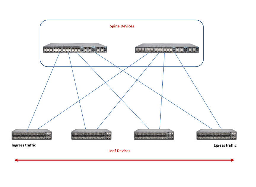
Typically, the spine devices are high-performance switches capable of Layer 3 switching and routing combined with high port density. Spine devices constitute the core and the leaf devices constitute the access layer in Layer 3 Fabrics. Leaf devices enable servers to connect to the Layer 3 Fabric. They also provide uplinks to spine devices.
Network Director currently supports only the 3-stage design. The 3-stage design has two roles—the spine and the leaf. It is called a 3-stage design because the traffic must traverse three switches in the worst-case scenario.
The maximum number of spine devices that you can have in your Layer 3 Fabric depends on the number of 40-Gigabit Ethernet interfaces in your leaf devices. A Layer 3 Fabric that has 8 QFX5100-24Q spine devices and 32 QFX5100-96S leaf devices (each leaf supports 96 10-Gigabit Ethernet ports) can provide 3072 usable 10-Gigabit Ethernet ports.