L3 (Layer 3) VPN
The L3 VPN is based on the IETF RFC 2547bis draft. To configure a L3 VPN (full-meshed version), the user would perform the following sequence of steps. Additional steps that are applicable only to configuring a L3 Hub-and-Spoke VPN are described in the subsequent section.
Assign a VPN/VRF name by bringing up the Add VPN window and selecting Layer 3. Then type in a name for the VPN (e.g. L3VPN_ph44).
Click on Next to bring up the window where you would choose the PEs of the VPN from the “Available PE Device(s)” list and add them to the right hand side “Selected PE Device(s)” list. Note that a node must be an iBGP speaker in order to make it into this list.
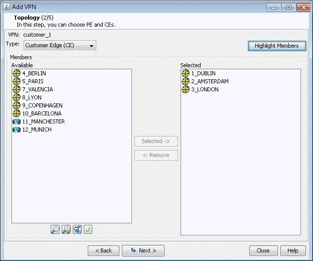
Here, you can also assign the Route Distinguisher, Route Target Exports, and Route Target Imports for the selected AS. The program automatically recommends initial values, which you may change.
Additionally, you may look up a list of Route Targets that are defined in the network by clicking on the magnifying glass icon to the right of the Import field to bring up the Route Targets Table shown below, which lists all the RTs (grouped by VPNs) in the network.
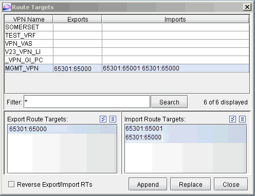
The Export Route Targets list and Import Route Targets list are populated with the route targets for the particular VPN selected. You may then choose any or all of the route targets to either append to or replace the route targets of the VPN you are currently adding. The Route Targets Table will help you to construct a VPN with various export/import relationships (e.g. extranet or hub-and-spoke type of relationships) with other VPNs. For our current example, we will be constructing a simple full-meshed L3 VPN, so we will not need to use the Route Targets table now.
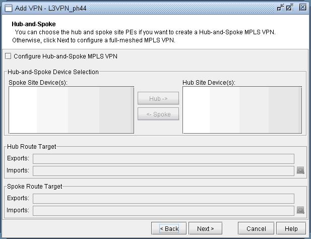
Clicking on Next takes you to the following screen, in which you can configure a Hub-and-Spoke VPN. Since we are configuring a full-meshed L3 VPN, click Next to skip over this step.
Click on Next to bring up the following window where you may add more PEs and assign the PE facing CE interfaces.
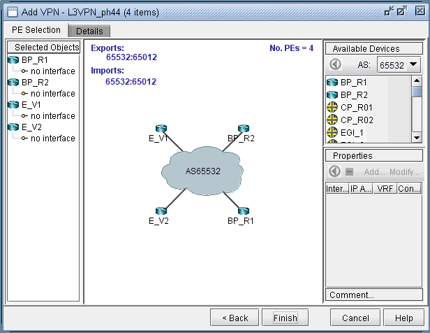
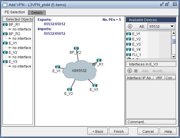
The middle part of the window shows the topology area, where selected PE routers are placed.
The Selected Objects area, as the name implies, lists those routers that have been selected as PEs.
The Available Devices box lists those routers for the currently chosen AS that are eligible (i.e., they must be iBGP speakers) to be selected as PE routers.
The Properties box lists all the interfaces for a particular router when it is highlighted (a router is highlighted when it is clicked on either from the Available Devices list, the topology area of the window, or from the Selected Objects list).
The window is designed to be as user-friendly as possible, with drag/drop capabilities built in. The following figure shows the four PEs that we have already added in the previous step.
In more detail, you may add additional PE routers to the VPN from the Available Devices box via one of two methods:
Select one or more routers (at which point the icon that has the left arrow with a circle around it will change color from gray to blue), and then click on the blue arrow/circle icon to move it to the topology area part of the window (middle of the window).
Alternatively, you could simply drag and drop PEs from the Available Devices list into the topology area of the window.
The following figure shows you the result of adding the fifth PE router (E_V3) to the VPN.
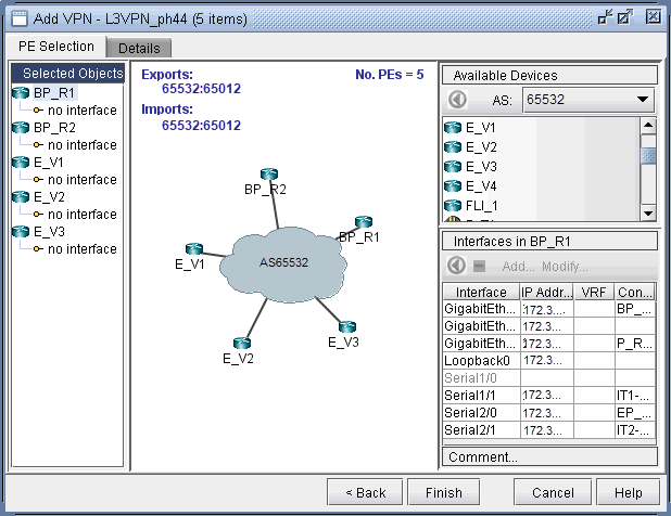
To assign the PE facing CE interfaces, first select a particular PE router in order to have all its interfaces shown in the Properties box. A PE is selected when it is clicked on from the Selected Objects list or from the topology area of the map. As shown in the following figure, the Properties box is now renamed as Interfaces in BP_R1, since the PE router BP_R1 has been selected. Another icon worth mentioning is the “–“/”+” button next to the arrow/circle button. Click on it to switch between “-“ and “+”. “-“ means to show all interfaces, while “+” means to only display interfaces that are unassigned or not shutdown.
To assign an interface, you need to drag and drop a particular interface over to a no interface item under a particular PE. Alternatively, you can select the PE from the left hand side, and then select an interface from the interface list on the bottom right hand side, and click the blue arrow in the Interfaces section. The following figure shows the window after the interfaces have been assigned to the PE routers.
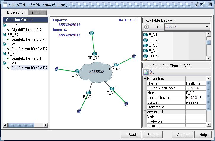
Note also the Add and Modify buttons in the Interface section. This can be used to add an additional interface, e.g., if you need to add a new subinterface, or to modify an existing interface.
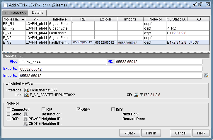
Next click on the Details tab to assign the PE-CE protocol. After selecting a row, you can choose OSPF, RIP, Static, BGP or connected as the protocol. The following figure shows OSPF being assigned as the PE-CE protocol.
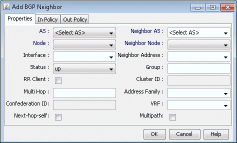
To assign BGP as the PE-CE protocol, first click on the BGP checkbox and then bring up the Add BGP Neighbor window (click on the icon to the left of PE->CE Neighbor IP or the icon to the left of CE->PE Neighbor IP), shown in the following figure. For more information about how to create BGP neighboring relationships, see NorthStar Planner Border Gateway Protocol Overview.
To assign Static as the PE-CE protocol, first click on the Static checkbox and then click on the icon to the right of Static to bring up the Add Static Route window.
To assign OSPF as the PE-CE protocol, first click on the OSPF checkbox and then click on the icon to the right of OSPF to bring up a dialog prompt, which allows you to enter in the associated OSPF PID (Cisco-only) and OSPF Protocol. The OSPF PID should be different from that of the network core, and the area should match the CE’s area.
Finally, click Finish to complete the adding of the L3VPN. The summary window then displays the VPN that you just added, as shown in the following figure.
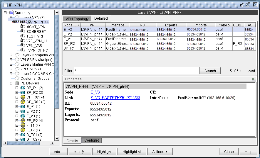
With the detailed view shown (select the Detailed tab) in the upper portion of the window, click the Configlet tab (next to the Details tab) to generate and display the configlet for the VPN that you just added.
