Removing and Installing Routing and Control Boards
Handling and Storing Routing and Control Boards
Holding Routing and Control Boards
Pay proper attention to the way you are holding Routing and Control Boards (RCBs). RCBs are installed horizontally and it is best to hold them by the sides of the units when they are not in the chassis.
To handle and store an RCB properly:
Storing Routing and Control Boards
You must store RCBs either in the chassis or in a spare shipping container, horizontally and sheet-metal side down. Do not stack these units on top of one another or on top of any other component. Place each unit separately in an antistatic bag or on an antistatic mat placed on a flat, stable surface.
Because these units are heavy, and because antistatic bags are fragile, inserting the line card into the bag is best done by two people.
To insert an RCB into an electrostatic bag:
- Hold the unit horizontally with the faceplate toward you.
- Have the second person slide the opening of the antistatic bag over the connector edge and then pull the bag to cover the unit.
If you must insert an RCB into a bag by yourself:
Lay the unit horizontally on an antistatic mat that is on a flat, stable surface with the sheet metal side down.
Orient the unit with the faceplate toward you.
Carefully insert the connector edge into the opening of the bag and pull the bag toward you to cover the unit.
Removing a Routing and Control Board
An MX10008 can have one or two Routing and Control Boards (RCBs), depending on the configuration. RCBs can be installed in either of the two top slots on the front of the chassis.
In redundant configurations, an RCB is a hot-removable and hot-insertable field-replaceable unit (FRU). In base configurations, you need to install a second RCB before removing a failing RCB in order to prevent the router from shutting down. We recommend that you take base systems offline before replacing the RCB.
Before you remove an RCB, ensure that you have the following items:
-
An electrostatic discharge (ESD) grounding strap
-
An antistatic mat
-
Cover panel for the empty slot if you are not replacing the RCB.
In base configurations, removal of the RCB causes the system to shut down. In redundant configurations, removal of the RCB causes the system to reboot and start the election process for a new primary.
To remove an RCB:
-
Wrap and fasten one end of an ESD strap around your bare
wrist, and connect the other end of the strap to the ESD point on
the chassis (see Figure 1).
Figure 1: ESD Point on the Front of an MX10008
 1—
1—ESD point
-
Grasp the handles, and slide the RCB about halfway out
of the chassis (see Figure 3).
Figure 2: Removing JNP10K-RE3 Routing and Control Board on MX10008
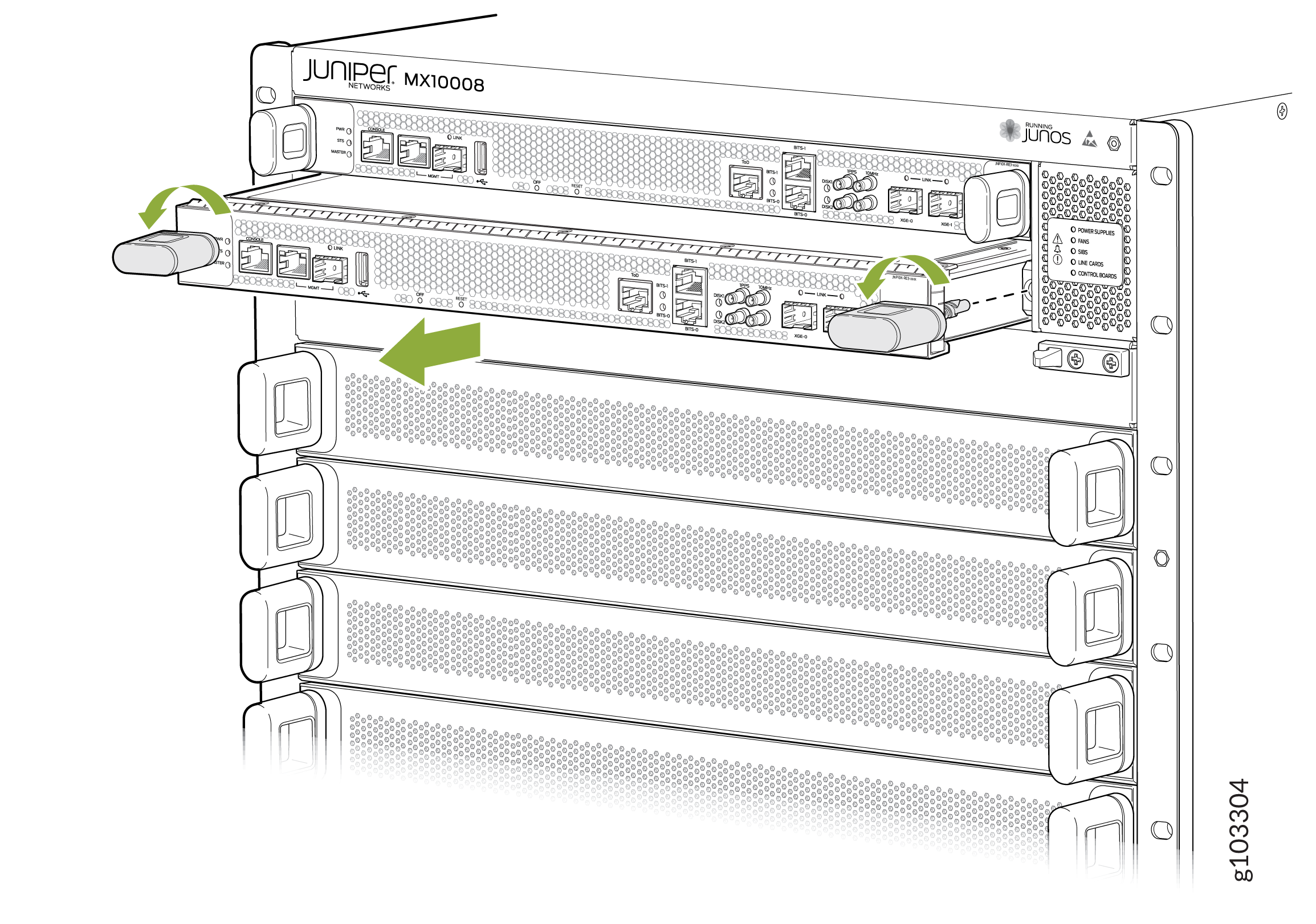 Figure 3: Removing JNP10K-RE1 Routing and Control Board on MX10008
Installing a Routing and Control Board
An MX10008 can have one or two Routing and Control Boards (RCBs), depending on the configuration. RCBs can be installed in either of the two top slots on the front of the chassis.
In redundant configurations, an RCB is a hot-removable and hot-insertable field-replaceable unit (FRU). In base configurations, you need to install a second RCB before removing a failing RCB in order to prevent the router from shutting down.
Before you install a RCB, ensure that you have an electrostatic discharge (ESD) grounding strap.
To install an RCB:
-
Wrap and fasten one end of an ESD strap around your bare
wrist, and connect the other end of the strap to the ESD point on
the front of an MX10008 (see Figure 4).
Figure 4: ESD Point for MX10008 Chassis Front
1—
ESD point
-
Either remove the cover panel from the available RCB slot (see Figure 5) or remove the failing RCB (see Removing a Routing and Control Board).
Figure 5: Removing a Routing and Control Board Cover Panel

-
Grasp both handles and simultaneously rotate them clockwise
until the RCB is fully seated and the handles are vertical (see Figure 7).
The RCB begins the power-on sequence after it is fully seated.
Figure 6: Installing JNP10K-RE3 Routing and Control Board on MX10008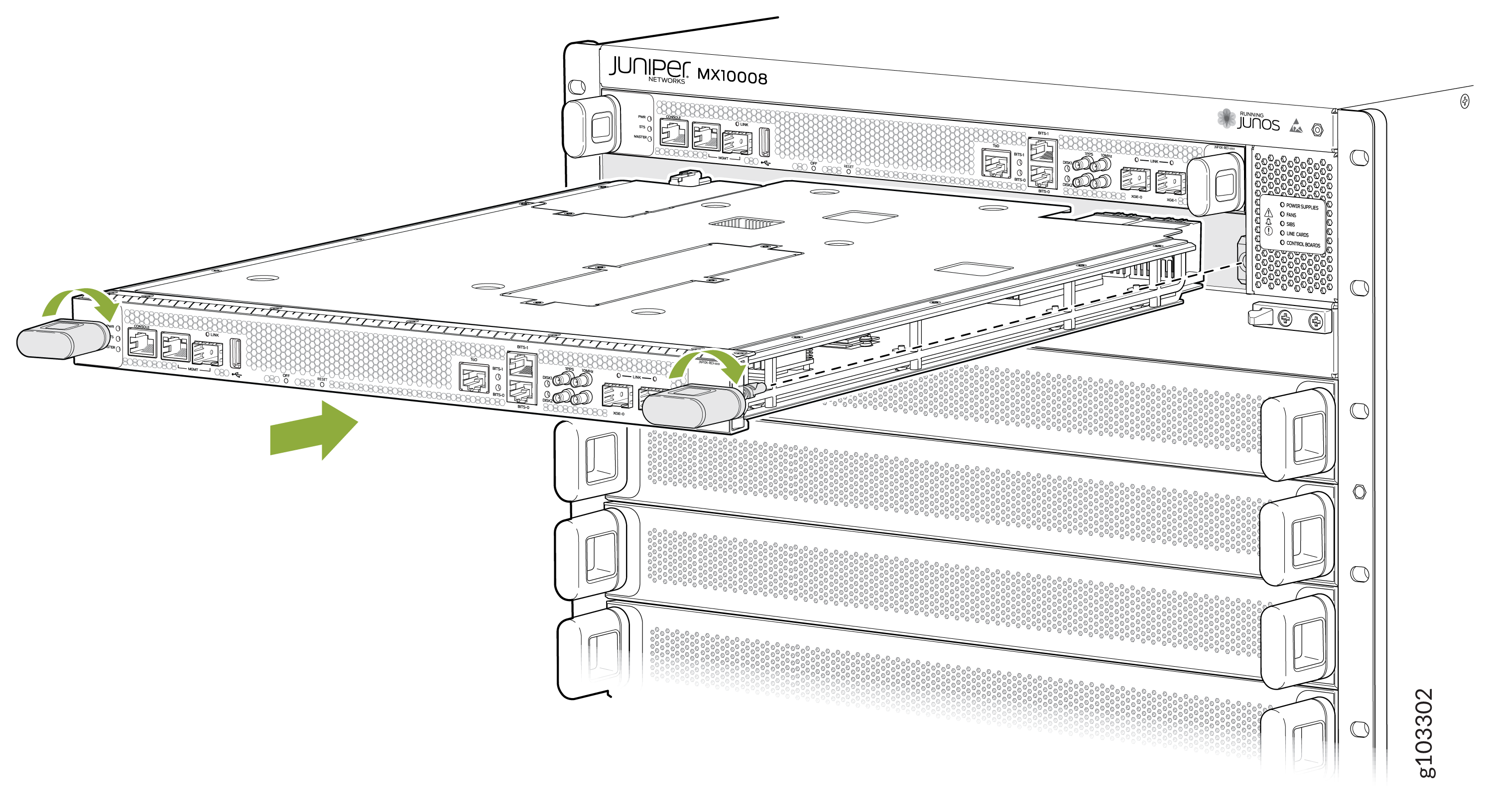 Figure 7: Installing JNP10K-RE1 Routing and Control Board Installation on MX10008