ON THIS PAGE
Fast Track to Rack Installation and Power
This procedure guides you through the simplest steps for the most common installation to mount your MX240 router in a rack and connect it to power.
Install the MX240 in a Rack
You can mount an MX240 router in a four-post rack, cabinet, or an open-frame rack. We'll walk you through the steps to install an MX240 router and connect it to power.
The router chassis weighs approximately 128 lb (58.1 kg) depending on the configuration.
You can mount the MX240 manually or using a mechanical lift. Because of the router's size and weight, we strongly recommend that you install the router using a mechanical lift.
Ensure that you have a mechanical lift rated for 250 lb (113.4 kg).
You must install the router in a restricted-access location and ensure that the chassis is always grounded properly.
Mount the router at the bottom of the rack if it is the only unit in the rack. On a partially filled rack, load the rack from the bottom to the top with the heaviest component at the bottom of the rack.
Before you install, review the following:
Mount the Router
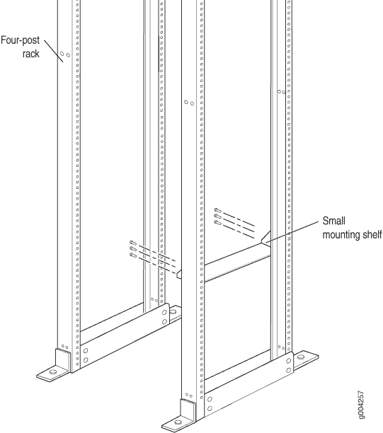
To mount the MX240 router on a four-post rack:
-
If needed, install cage nuts in the holes specified in Table 1.
Table 1: Four-Post Rack Mounting Hole Locations Hole
Distance Above U Division
Mounting Shelf
4
2.00 in. (5.1 cm)
1.14 U
X
3
1.51 in. (3.8 cm)
0.86 U
X
2
0.88 in. (2.2 cm)
0.50 U
X
1
0.25 in. (0.6 cm)
0.14 U
X
-
On the back of each rack rail, partially insert a mounting screw into the lowest hole specified in Table 1.
-
Install the small shelf on the back of the rack rails. Rest the bottom slot of each flange on a mounting screw.

-
Partially insert the remaining screws into the open holes in each flange of the small shelf.
-
Tighten all the screws completely.
-
Attach an electrostatic discharge (ESD) grounding strap to your bare wrist and connect the strap to an approved site ESD grounding point.
-
Because of the router's size and weight, remove all components before installing the router.


The following components must be removed:
-
Power supplies
-
Switch Control Boards (SCBs)
-
Routing Engines
-
Air filter
-
Fan tray
-
Line cards
-
Dense Port Concentrators (DPCs)
-
Flexible PIC Concentrators (FPCs)
-
Physical Interface Cards (PICs)
-
Modular Port Concentrators (MPCs)
-
Modular Interface Cards (MICs)
-
To remove components from the router:
-
Slide each component out of the chassis evenly so that it does not become stuck or damaged.
-
Label each component as you remove it so you can reinstall it in the correct location.
-
Immediately store each removed component in an electrostatic bag.
-
Do not stack removed components. Lay each one on a flat surface.
Note:For complete instructions on removing router components, see Removing Components from the MX240 Router Before Installing it with a Lift.
-
-
Load the router onto the lift, making sure it rests securely on the lift platform.

-
Using the lift, position the router in front of the rack or cabinet, centering it in front of the mounting shelf.
-
Lift the chassis approximately 0.75 in. above the surface of the mounting shelf and position it as close as possible to the shelf.
-
Carefully slide the router onto the mounting shelf so that the bottom of the chassis and the mounting shelf overlap by approximately 2 inches.
-
Slide the router onto the mounting shelf until the mounting brackets contact the rack rails. The shelf ensures that the holes in the mounting brackets align with the holes in the rack rails.
-
Move the lift away from the rack.
-
Install a mounting screw into each of the open mounting holes aligned with the rack, starting from the bottom.
-
Visually inspect the alignment of the router. If the router is installed properly in the rack, all the mounting screws on one side of the rack should be aligned with the mounting screws on the opposite side, and the router should be level.
-
Reinstall components in the router:
-
Slide each component into the chassis evenly so that it does not become stuck or damaged.
-
Tighten the captive screws for each component.
Note:For complete instructions on reinstalling the router components, see Reinstalling Components in the MX240 Router After Installing it with a Lift.
-
Connect to Power
Now that you've mounted your router on the rack, you're ready to ground your router and connect it to power. Depending on your configuration, your router uses either normal-capacity or high-capacity AC or DC power supplies. In this guide, we show you how to connect to normal-capacity AC power.
Do not mix AC and DC power supply modules within the same device. Mixing currents can damage the device.
To connect the MX240 router to AC power:
Ground the Router
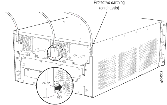
To meet safety and electromagnetic interference (EMI) requirements and to ensure proper operation, you must connect the chassis to earth ground. You ground the router by connecting a grounding cable to earth ground and then attaching it to the chassis grounding points using two UNC 1/4-20 screws. Make this connection before you connect the router to power.
To connect the MX240 router to earth ground:
-
Verify that a licensed electrician has attached the cable lug provided with the router to the grounding cable.
- Attach an electrostatic discharge (ESD) grounding strap to your bare wrist and connect the strap to an approved site ESD grounding point. See the instructions for your site.
- Ensure that all grounding surfaces are clean and brought to a bright finish before grounding connections are made.
- Connect the grounding cable to a proper earth ground.
- Detach the ESD grounding strap from the site ESD grounding point.
- Attach an electrostatic discharge (ESD) grounding strap to your bare wrist and connect the strap to one of the ESD points on the chassis.
- Place the grounding cable lug over the grounding points on the upper rear of the chassis. The bolts are sized for UNC 1/4-20 screws.
- Secure the grounding cable lug to the grounding points, first with the washers, then with the screws.
- Dress the grounding cable and verify that it does not touch or block access to router components, and that it does not drape where people could trip on it.
Connect the Power Cable and Power On the Router
To connect the power cable and power on the MX240 router:
-
Locate the power cords shipped with the router, which should have a plug appropriate for your geographical location.
-
Move the AC input switch next to the appliance inlet on the power supply to the off (O) position.
-
Insert the appliance coupler end of the power cord into the appliance inlet on the power supply.
-
Connect the power cord to the power supply.

-
Insert the power cord plug into an external AC power source receptacle.
Note:Each power supply must be connected to a dedicated AC power feed and a dedicated customer site circuit breaker. We recommend that you use a dedicated customer site circuit breaker rated for 15 A (250 VAC) minimum, or as permitted by local code.
-
Route the power cord appropriately. Verify that the power cord does not block the air exhaust and access to router components, or drape where people could trip on it.
-
Switch the AC input switch on each power supply to the on (|) position and observe the status LEDs on each power supply faceplate. If an AC power supply is correctly installed and functioning normally, the AC OK and DC OK LEDs light steadily, and the PS FAIL LED is not lit.
If any of the status LEDs indicates that the power supply is not functioning normally, repeat the installation and cabling procedures.
