Maintaining MX480 Cooling System Components
Maintaining the MX480 Air Filter
Purpose
For optimum cooling, verify the condition of the air filters.
Action
Regularly inspect the air filter. A dirty air filter restricts airflow in the unit, producing a negative effect on the ventilation of the device. The filter degrades over time. You must replace the filter every 6 months.
CAUTION:Always keep the air filter in place while the device is operating, except during replacement. The fans are very powerful and can pull small bits of wire or other materials into the device if the air filter isn't in place. These materials can damage device components.
The shelf life of polyurethane filter varies from two years to five years depending on the storage conditions. Store in a cool, dry, and dark environment. Wrap the media in plastic and store in an environment with relative humidity between 40%- 80% and temperature between 40° F (4° C) to 90° F (32° C). Note that if the material flakes, or becomes brittle when rubbed or deformed, it is no longer usable.
Replacing the MX480 Air Filter
Removing the MX480 Air Filter
Do not run the device for more than a few minutes without the air filter in place.
Always keep the air filter in place while the device is operating, except during replacement. The fans are very powerful and can pull small bits of wire or other materials into the device if the air filter isn't in place. These materials can damage device components.
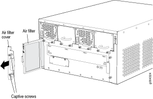
To remove the air filter (see Figure 1):
- Attach an ESD grounding strap to your bare wrist, and connect the other end of the strap to an ESD grounding point.
- Loosen the captive screws on the air filter cover.
- Remove the air filter cover.
- Slide the air filter out of the chassis.

See Also
Installing the MX480 Air Filter
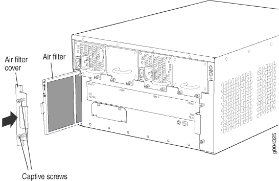
To install the air filter (see Figure 2):
- Attach an ESD grounding strap to your bare wrist, and connect the other end of the strap to an ESD grounding point.
- Locate the up arrow and ensure that the air filter is right side up.
- Slide the air filter straight into the chassis until it stops.
- Align the captive screws of the air filter cover with the mounting holes on the chassis.
- Tighten the captive screws on the air filter cover.

Maintaining the MX480 Fan Tray
Purpose
For optimum cooling, verify the condition of the fans.
Action
Monitor the status of the fans. A fan tray contains multiple fans that work in unison to cool the router components. If one fan fails, the host subsystem adjusts the speed of the remaining fans to maintain proper cooling. A red alarm is triggered when a fan fails, and a yellow alarm and red alarm is triggered when a fan tray is removed.
To display the status of the cooling system, issue the show chassis environment command. The output is similar to the following:
user@host> show chassis environment

Class Item                           Status     Measurement
Temp  PEM 0                          OK         40 degrees C / 104 degrees F
      PEM 1                          Absent
      PEM 2                          Absent
      PEM 3                          OK         40 degrees C / 104 degrees F
      Routing Engine 0               OK         39 degrees C / 102 degrees F
      Routing Engine 1               OK         42 degrees C / 107 degrees F
      CB 0 Intake                    OK         26 degrees C / 78 degrees F
      CB 0 Exhaust A                 OK         27 degrees C / 80 degrees F
      CB 0 Exhaust B                 OK         27 degrees C / 80 degrees F
      CB 0 ACBC                      OK         26 degrees C / 78 degrees F
      CB 0 SF A                      OK         37 degrees C / 98 degrees F
      CB 0 SF B                      OK         35 degrees C / 95 degrees F
      CB 1 Intake                    OK         27 degrees C / 80 degrees F
      CB 1 Exhaust A                 OK         30 degrees C / 86 degrees F
      CB 1 Exhaust B                 OK         28 degrees C / 82 degrees F
      CB 1 ACBC                      OK         27 degrees C / 80 degrees F
      CB 1 SF A                      OK         36 degrees C / 96 degrees F
      CB 1 SF B                      OK         36 degrees C / 96 degrees F
      CB 2 Intake                    Absent
      CB 2 Exhaust A                 Absent
      CB 2 Exhaust B                 Absent
      CB 2 ACBC                      Absent
      CB 2 SF A                      Absent
      CB 2 SF B                      Absent
      FPC 2 Intake                   OK         22 degrees C / 71 degrees F
      FPC 2 Exhaust A                OK         27 degrees C / 80 degrees F
      FPC 2 Exhaust B                OK         33 degrees C / 91 degrees F
      FPC 2 I3 0 TSensor             OK         33 degrees C / 91 degrees F
      FPC 2 I3 0 Chip                OK         35 degrees C / 95 degrees F
      FPC 2 I3 1 TSensor             OK         33 degrees C / 91 degrees F
      FPC 2 I3 1 Chip                OK         33 degrees C / 91 degrees F
      FPC 2 I3 2 TSensor             OK         33 degrees C / 91 degrees F
      FPC 2 I3 2 Chip                OK         30 degrees C / 86 degrees F
      FPC 2 I3 3 TSensor             OK         30 degrees C / 86 degrees F
      FPC 2 I3 3 Chip                OK         30 degrees C / 86 degrees F
      FPC 2 IA 0 TSensor             OK         33 degrees C / 91 degrees F
      FPC 2 IA 0 Chip                OK         36 degrees C / 96 degrees F
      FPC 2 IA 1 TSensor             OK         30 degrees C / 86 degrees F
      FPC 2 IA 1 Chip                OK         35 degrees C / 95 degrees F
      FPC 4 Intake                   OK         22 degrees C / 71 degrees F
      FPC 4 Exhaust A                OK         28 degrees C / 82 degrees F
      FPC 4 Exhaust B                OK         31 degrees C / 87 degrees F
      FPC 4 I3 0 TSensor             OK         31 degrees C / 87 degrees F
      FPC 4 I3 0 Chip                OK         34 degrees C / 93 degrees F
      FPC 4 I3 1 TSensor             OK         31 degrees C / 87 degrees F
      FPC 4 I3 1 Chip                OK         33 degrees C / 91 degrees F
      FPC 4 I3 2 TSensor             OK         31 degrees C / 87 degrees F
      FPC 4 I3 2 Chip                OK         29 degrees C / 84 degrees F
      FPC 4 I3 3 TSensor             OK         29 degrees C / 84 degrees F
      FPC 4 I3 3 Chip                OK         29 degrees C / 84 degrees F
      FPC 4 IA 0 TSensor             OK         35 degrees C / 95 degrees F
      FPC 4 IA 0 Chip                OK         37 degrees C / 98 degrees F
      FPC 4 IA 1 TSensor             OK         31 degrees C / 87 degrees F
      FPC 4 IA 1 Chip                OK         35 degrees C / 95 degrees F
      FPC 7 Intake                   OK         20 degrees C / 68 degrees F
      FPC 7 Exhaust A                OK         21 degrees C / 69 degrees F
      FPC 7 Exhaust B                OK         21 degrees C / 69 degrees F
      FPC 7 I3 0 TSensor             OK         31 degrees C / 87 degrees F
      FPC 7 I3 0 Chip                OK         36 degrees C / 96 degrees F
      FPC 7 I3 1 TSensor             OK         32 degrees C / 89 degrees F
      FPC 7 I3 1 Chip                OK         35 degrees C / 95 degrees F
      FPC 7 I3 2 TSensor             OK         32 degrees C / 89 degrees F
      FPC 7 I3 2 Chip                OK         30 degrees C / 86 degrees F
      FPC 7 I3 3 TSensor             OK         30 degrees C / 86 degrees F
      FPC 7 I3 3 Chip                OK         31 degrees C / 87 degrees F
      FPC 7 IA 0 TSensor             OK         34 degrees C / 93 degrees F
      FPC 7 IA 0 Chip                OK         37 degrees C / 98 degrees F
      FPC 7 IA 1 TSensor             OK         31 degrees C / 87 degrees F
      FPC 7 IA 1 Chip                OK         35 degrees C / 95 degrees F
Fans  Top Fan Tray Temp              OK         27 degrees C / 80 degrees F
      Top Tray Fan 1                 OK         Spinning at high speed
      Top Tray Fan 2                 OK         Spinning at high speed
      Top Tray Fan 3                 OK         Spinning at high speed
      Top Tray Fan 4                 OK         Spinning at high speed
      Top Tray Fan 5                 OK         Spinning at high speed
      Top Tray Fan 6                 OK         Spinning at high speed
      Bottom Fan Tray Temp           OK         28 degrees C / 82 degrees F
      Bottom Tray Fan 1              OK         Spinning at high speed
      Bottom Tray Fan 2              OK         Spinning at high speed
      Bottom Tray Fan 3              OK         Spinning at high speed
      Bottom Tray Fan 4              OK         Spinning at high speed
      Bottom Tray Fan 5              OK         Spinning at high speed
      Bottom Tray Fan 6              OK         Spinning at high speed
See Also
Replacing the MX480 Fan Tray
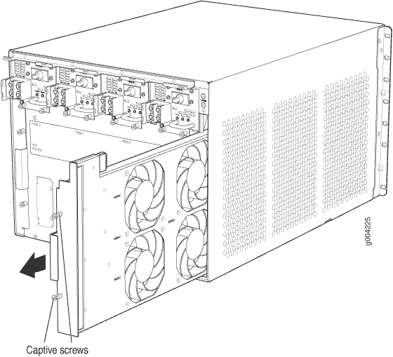
Removing the MX480 Fan Tray
To prevent overheating, install the replacement fan tray immediately after removing the existing fan tray.
To remove the fan tray (see Figure 3):

Installing the MX480 Fan Tray
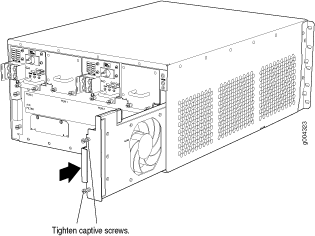
To install the fan tray (see Figure 4):
- Attach an ESD grounding strap to your bare wrist, and connect the other end of the strap to an ESD grounding point.
- Grasp the fan tray handle, and insert it straight into the chassis. Note the correct orientation by the this side up label on the top surface of the fan tray.
- Tighten the captive screws on the fan tray faceplate to secure it in the chassis.

