Help us improve your experience.

Let us know what you think.

Do you have time for a two-minute survey?


Maintaining MX480 Interface Modules

Maintaining MX480 DPCs

Purpose

The router can have up to six Dense Port Concentrators (DPCs) mounted horizontally in the DPC card cage at the front of the chassis. For optimum router performance, verify the condition of the DPCs.

Action

On a regular basis:

  • Check the LEDs on the craft interface directly above each DPC slot. The green LED labeled OK lights steadily when a DPC is functioning normally.

  • Check the OK/FAIL LED on the DPC. For more information, seeMX Series Interface Module Reference . If the DPC detects a failure, the DPC sends an alarm message to the Routing Engine.

  • Check the status of installed DPCs by issuing the CLI show chassis fpc command to check the status of installed DPCs. As shown in the sample output, the value Online in the column labeled State indicates that the DPC is functioning normally:

    For more detailed output, add the detail option. The following example does not specify a slot number, which is optional:

  • Issue the CLI show chassis fpc pic-status command. The DPC slots are numbered 0 through 5, bottom to top:

    For further description of the output from the command, see the CLI Explorer.

Holding an MX480 DPC

When carrying a DPC, you can hold it either vertically or horizontally.

Note:

A DPC weighs 14.5 lb (6.6 kg). Be prepared to accept the full weight of the DPC as you lift it.

To hold a DPC vertically:

  1. Orient the DPC so that the faceplate faces you. To verify orientation, confirm that the text on the DPC is right-side up and the electromagnetic interference (EMI) strip is on the right-hand side.
  2. Place one hand around the DPC faceplate about a quarter of the way down from the top edge. To avoid deforming the EMI shielding strip, do not press hard on it.
  3. Place your other hand at the bottom edge of the DPC.

If the DPC is horizontal before you grasp it, place your left hand around the faceplate and your right hand along the bottom edge.

To hold a DPC horizontally:

  1. Orient the DPC so that the faceplate faces you.

  2. Grasp the top edge with your left hand and the bottom edge with your right hand.

You can rest the faceplate of the DPC against your body as you carry it.

As you carry the DPC, do not bump it against anything. DPC components are fragile.

Never hold or grasp the DPC anywhere except places that this document indicates. In particular, never grasp the connector edge, especially at the power connector in the corner where the connector and bottom edges meet. See Figure 1.
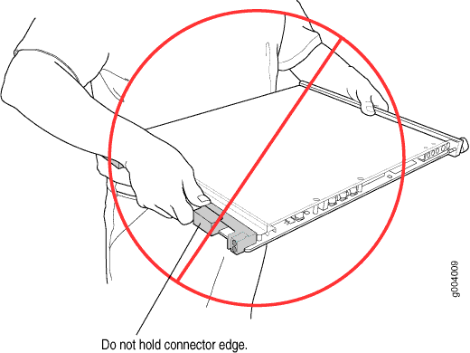
Figure 1: Do Not Grasp the Connector EdgeDo Not Grasp the Connector Edge

Never carry the DPC by the faceplate with only one hand.

Do not rest any edge of a DPC directly against a hard surface (see Figure 2).

Do not stack DPCs.
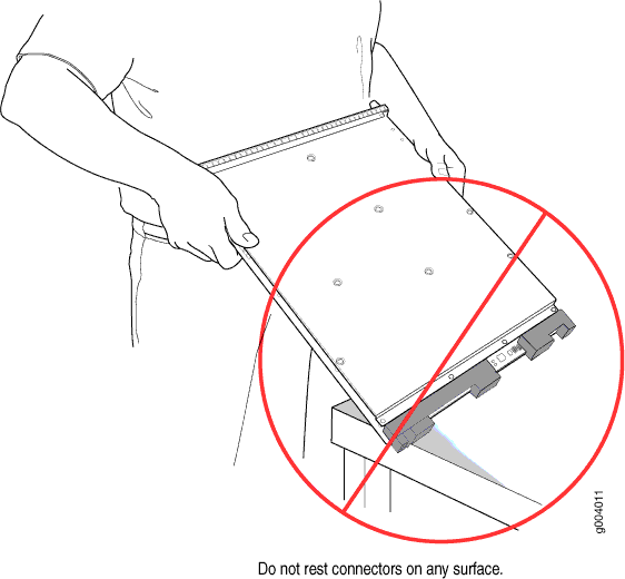
Figure 2: Do Not Rest the DPC on an EdgeDo Not Rest the DPC on an Edge

If you must rest the DPC temporarily on an edge while changing its orientation between vertical and horizontal, use your hand as a cushion between the edge and the surface.

Storing an MX480 DPC

You must store a DPC as follows:

  • In the router

  • In the container in which a spare DPC is shipped

  • Horizontally and sheet metal side down

When you store a DPC on a horizontal surface or in the shipping container, always place it inside an antistatic bag. Because the DPC is heavy, and because antistatic bags are fragile, inserting the DPC into the bag is easier with two people. To do this, one person holds the DPC in the horizontal position with the faceplate facing the body, and the other person slides the opening of the bag over the DPC connector edge.

If you must insert the DPC into a bag by yourself, first lay the DPC horizontally on a flat, stable surface, sheet metal side down. Orient the DPC with the faceplate facing you. Carefully insert the DPC connector edge into the opening of the bag, and pull the bag toward you to cover the DPC.

Never stack a DPC under or on top of any other component.

Replacing an MX480 DPC

Removing an MX480 DPC

A DPC weighs up to 13.1 lb (5.9 kg). Be prepared to accept its full weight.

To remove a DPC (see Figure 3):
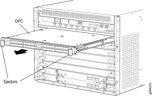
  1. Have ready a replacement DPC or DPC blank panel and an antistatic mat for the DPC. Also have ready rubber safety caps for each DPC you are removing that uses an optical interface.
  2. Attach an ESD grounding strap to your bare wrist, and connect the other end of the strap to an ESD grounding point.
  3. Label the cables connected to each port on the DPC so that you can later reconnect the cables to the correct ports.
  4. Use one of the following methods to take the DPC offline:
    • Press and hold the corresponding DPC online button on the craft interface. The green OK LED next to the button begins to blink. Hold the button down until the LED goes off.

    • Issue the following CLI command:

      For more information about the command, see the CLI Explorer.

  5. Disconnect the cables from the DPC.
    Laser Warning:

    Do not look directly into a fiber-optic transceiver or into the ends of fiber-optic cables. Fiber-optic transceivers and fiber-optic cables connected to a transceiver emit laser light that can damage your eyes.

    CAUTION:

    Do not leave a fiber-optic transceiver uncovered, except when you are inserting or removing cable. The safety cap keeps the port clean and protects your eyes from accidental exposure to laser light.

    CAUTION:

    Do not bend a fiber-optic cable beyond its minimum bend radius. An arc smaller than a few inches in diameter can damage the cable and cause problems that are difficult to diagnose.

  6. Immediately cover each optical transceiver and the end of each fiber-optic cable with a rubber safety cap.
  7. Arrange the disconnected cables in the cable management brackets to prevent the cables from developing stress points.
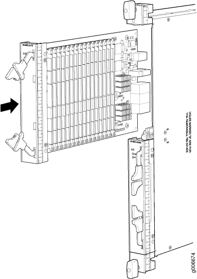
  8. Simultaneously turn both of the ejector handles counterclockwise to unseat the DPC.
  9. Grasp the handles, and slide the DPC straight out of the card cage halfway.
  10. Place one hand around the front of the DPC and the other hand under it to support it. Slide the DPC completely out of the chassis, and place it on the antistatic mat or in the electrostatic bag.
    CAUTION:

    The weight of the DPC is concentrated in the back end. Be prepared to accept the full weight—up to 13.1 lb (5.9 kg)—as you slide the DPC out of the chassis.

    When the DPC is out of the chassis, do not hold it by the ejector handles, bus bars, or edge connectors. They cannot support its weight.

    Do not stack DPCs on top of one another after removal. Place each one individually in an electrostatic bag or on its own antistatic mat on a flat, stable surface.

  11. If you are not reinstalling a DPC into the emptied DPC slot within a short time, install a blank DPC panel over the slot to maintain proper airflow in the DPC card cage.
    CAUTION:

    After removing a DPC from the chassis, wait at least 30 seconds before reinserting it, removing a DPC from a different slot, or inserting a DPC into a different slot.

Figure 3: Removing a DPCRemoving a DPC

Installing an MX480 DPC

A DPC weighs up to 14.5 lb (6.6 kg). Be prepared to accept its full weight.

To install a DPC (see Figure 4):

  1. Attach an ESD grounding strap to your bare wrist, and connect the other end of the strap to an ESD grounding point.
  2. Place the DPC on an antistatic mat, or remove it from its electrostatic bag.
  3. Identify the slot on the router where it will be installed.
  4. Verify that each fiber-optic transceiver is covered with a rubber safety cap. If it does not, cover the transceiver with a safety cap.
  5. Orient the DPC so that the faceplate faces you.
  6. Lift the DPC into place, and carefully align the sides of the DPC with the guides inside the card cage.
  7. Slide the DPC all the way into the card cage until you feel resistance.
  8. Grasp both ejector handles, and rotate them clockwise simultaneously until the DPC is fully seated.
  9. Remove the rubber safety cap from each fiber-optic transceiver and cable.
    Laser Warning:

    Do not look directly into a fiber-optic transceiver or into the ends of fiber-optic cables. Fiber-optic transceivers and fiber-optic cables connected to a transceiver emit laser light that can damage your eyes.

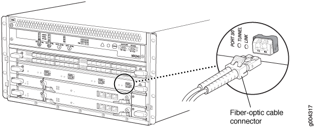
  10. Insert the cables into the cable connector ports on each DPC (see Figure 5).
  11. Arrange the cable to prevent it from dislodging or developing stress points. Secure the cable so that it is not supporting its own weight as it hangs to the floor. Place excess cable out of the way in a neatly coiled loop.
    CAUTION:

    Do not let fiber-optic cables hang free from the connector. Do not allow the fastened loops of a cable to dangle, which stresses the cable at the fastening point.

    CAUTION:

    Do not bend a fiber-optic cable beyond its minimum bend radius. An arc smaller than a few inches in diameter can damage the cable and cause problems that are difficult to diagnose.

  12. Use one of the following methods to bring the DPC online:
    • Press and hold the corresponding DPC online button on the craft interface until the green OK LED next to the button lights steadily, in about 5 seconds.

    • Issue the following CLI command:

      For more information about the command, see the CLI Explorer.

    CAUTION:

    After the OK LED turns green, wait at least 30 seconds before removing the DPC again, removing a DPC from a different slot, or inserting a DPC in a different slot.

You can also verify that the DPC is functioning correctly by issuing the show chassis fpc and show chassis fpc pic-status commands.
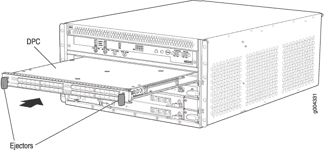
Figure 4: Installing a DPCInstalling a DPC
Figure 5: Attaching a Cable to a DPCAttaching a Cable to a DPC

Replacing a Cable on an MX480 DPC, MPC, MIC, or PIC

Removing a Cable on an MX480 DPC, MPC, MIC, or PIC

Removing and installing cables on a DPC, MPC, MIC, or PIC does not affect router function.

To remove a cable:

  1. Have ready a rubber safety cap for each fiber-optic cable and transceiver.
  2. If removing all cables connected to the component, use one of the following methods to take the component offline:
    • To take a DPC or an MPC offline:

      • Press and hold the corresponding online button on the craft interface. The green OK LED next to the button begins to blink. Hold the button down until the LED goes off.

      • Issue the following CLI command:

        For more information about the command, see the CLI Explorer.

    • To take a PIC offline:

      • Press the online/offline button on the PIC. For a PIC installed in an FPC3, use a narrow-ended tool that fits inside the opening that leads to the button. Press and hold the button until the PIC LED goes off (about 5 seconds).

      • Issue the following CLI command:

        For more information about the command, see the CLI Explorer.

    • To take a MIC offline:

      • Press the online/offline button on the MIC. Use a narrow-ended tool that fits inside the opening that leads to the button. Press and hold the button until the MIC LED goes off (about 5 seconds).

      • Issue the following CLI command:

        For more information about the command, see the CLI Explorer.

  3. Disconnect the cable from the cable connector port. If the component uses fiber-optic cable, immediately cover each transceiver and the end of each cable with a rubber safety cap.
    Laser Warning:

    Do not look directly into a fiber-optic transceiver or into the ends of fiber-optic cables. Fiber-optic transceivers and fiber-optic cables connected to a transceiver emit laser light that can damage your eyes.

    CAUTION:

    Do not leave a fiber-optic transceiver uncovered, except when you are inserting or removing cable. The safety cap keeps the port clean and protects your eyes from accidental exposure to laser light.

  4. Remove the cable from the cable management brackets.
  5. Disconnect the cable from the destination port.

Installing a Cable on an MX480 DPC, MPC, MIC, or PIC

To install a cable:

  1. Have ready a length of the type of cable used by the DPC, MPC, MIC, or PIC. For cable specifications, see the MX Series Interface Module Reference.
  2. If the cable connector port is covered by a rubber safety plug, remove the plug.
    Laser Warning:

    Do not look directly into a fiber-optic transceiver or into the ends of fiber-optic cables. Fiber-optic transceivers and fiber-optic cables connected to a transceiver emit laser light that can damage your eyes.

    CAUTION:

    Do not leave a fiber-optic transceiver uncovered, except when you are inserting or removing cable. The safety cap keeps the port clean and protects your eyes from accidental exposure to laser light.

  3. Insert the cable connector into the cable connector port on the component faceplate.
  4. Arrange the cable in the cable management brackets to prevent it from dislodging or developing stress points. Secure the cable so that it is not supporting its own weight as it hangs to the floor. Place excess cable out of the way in a neatly coiled loop. Placing fasteners on the loop helps to maintain its shape.
    CAUTION:

    Do not let fiber-optic cables hang free from the connector. Do not allow the fastened loops of a cable to dangle, which stresses the cable at the fastening point.

    CAUTION:

    Do not bend a fiber-optic cable beyond its minimum bend radius. An arc smaller than a few inches in diameter can damage the cable and cause problems that are difficult to diagnose.

  5. Insert the other end of the cable into the destination port.
  6. Repeat the previous steps for any additional cables.
  7. If the component is offline (its failure indicator LED is lit), use one of the following methods to bring the it online:
    • To bring a DPC or an MPC online:

      • Press and hold the corresponding online button on the craft interface until the green OK LED next to the button lights steadily, in about 5 seconds.

      • Issue the following CLI command:

        For more information about the command, see the CLI Explorer.

    • To bring a PIC online:

      • Press the PIC offline/online button until the PIC LED lights green. For a PIC installed in an FPC2 or FPC3, use a narrow-ended tool that fits inside the opening that leads to the button.

      • Issue the following CLI command:

        For more information about the command, see the CLI Explorer.

    • To bring a MIC online:

      • Press the MIC offline/online button until the MIC LED lights green.

      • Issue the following CLI command:

        For more information about the command, see the CLI Explorer.

    The normal functioning indicator LED confirms that the component is online. You can also verify correct DPC or MPC functioning by issuing the show chassis fpc command or correct MIC or the PIC functioning by issuing the show chassis fpc pic-status command.

Maintaining MX480 FPCs

Purpose

The MX480 router can have up to three Flexible PIC Concentrators (FPCs) installed horizontally in the front of the chassis. For optimum router performance, verify the condition of the FPC.

Action

On a regular basis:

  • Check the LEDs on the craft interface directly above the FPC. The green LED labeled OK lights steadily when an FPC is functioning normally.

  • Check the OK/FAIL LED on the FPC. If the FPC detects a failure, the FPC sends an alarm message to the Routing Engine.

  • Issue the CLI show chassis fpc command to check the status of the installed FPC. As shown in the sample output, the value Online in the column labeled State indicates that the FPC is functioning normally:

    For more detailed output, add the detail option. The following example does not specify a slot number, which is optional:

  • Issue the CLI show chassis fpc pic-status command. The following example shows an FPC installed in DPC slots 0, and 1:

    Note:

    An FPC takes up two DPC slots when installed on an MX Series router. The slot number corresponds to the lowest numbered DPC slot.

    For further description of the output from the command, see the CLI Explorer.

Holding an MX480 FPC

CAUTION:

Many components on the FPC are fragile. Failure to handle FPCs as specified in this document can cause irreparable damage.

Note:

An FPC configured with PICs installed can weigh as much as 18 lb (8.2 kg). Be prepared to accept the full weight of the FPC as you lift it.

CAUTION:

To prevent damage when handling or carrying FPCs:

  • As you carry the FPC, do not bump it against anything. FPC components are fragile.

  • Do not grasp the FPC anywhere except places that this document indicates. In particular, never grasp the connector edge, especially at the power connector in the corner where the connector and bottom edges meet (see Figure 6).

    Figure 6: Do Not Grasp the Connector EdgeDo Not Grasp the Connector Edge
  • Do not carry the FPC by the faceplate with only one hand (see Figure 7).

    Figure 7: Do Not Carry an FPC with Only One HandDo Not Carry an FPC with Only One Hand
  • Do not rest any edge of an FPC directly against a hard surface (see Figure 8). If you must rest the FPC temporarily on an edge while changing its orientation between vertical and horizontal, use your hand as a cushion between the edge and the surface.

    Figure 8: Do Not Rest the FPC on an EdgeDo Not Rest the FPC on an Edge

You hold an FPC horizontally when installing it into the chassis or an equipment rack.

If the FPC is horizontal before you grasp it, place your left hand around the faceplate and your right hand along the bottom edge.

To hold an FPC horizontally:

  1. Orient the FPC so that the faceplate faces you.
  2. Grasp the top edge with your left hand and the bottom edge with your right hand.

Storing an MX480 FPC

When not installed in the routing platforms, FPCs must be either stored in the container in which a spare FPC is shipped or stored horizontally with the component-side up on a flat, stable surface. When you store an FPC on a horizontal surface or in the shipping container, always place it inside an antistatic bag. Because the FPC is heavy and because antistatic bags are fragile, inserting the FPC into the bag is easier with two people. The storage guidelines are as follows:

  • When storing an FPC with two people, one person holds the FPC in the horizontal position with the faceplate facing their body, the other person slides the opening of the bag over the FPC connector edge.

  • When storing an FPC with one person, you must insert the FPC into a bag by yourself. First lay the FPC horizontally on a flat, stable surface, component-side up. Orient the FPC with the faceplate facing you. Carefully insert the FPC connector edge into the opening of the bag, and pull the bag toward you to cover the FPC.

CAUTION:

To prevent damage when storing FPCs:

  • Never lay an FPC component-side down.

    Figure 9: Do Not Stack FPCsDo Not Stack FPCs
  • Never stack an FPC under or on top of any other component (see Figure 9).

Replacing an MX480 FPC

Removing an MX480 FPC

When you remove an FPC, the router continues to function, although the PIC interfaces installed on the FPC being removed no longer function.

An FPC takes up two DPC slots on the MX480 router. Up to three FPCs can be installed horizontally in the front of the MX480 router. The FPCs are hot-insertable and hot-removable. An empty FPC3 weighs 14 lb (6.5 kg). A fully configured FPC can weigh up to 18 lb (8.2 kg). Be prepared to accept its full weight.

To remove an FPC (see Figure 10):
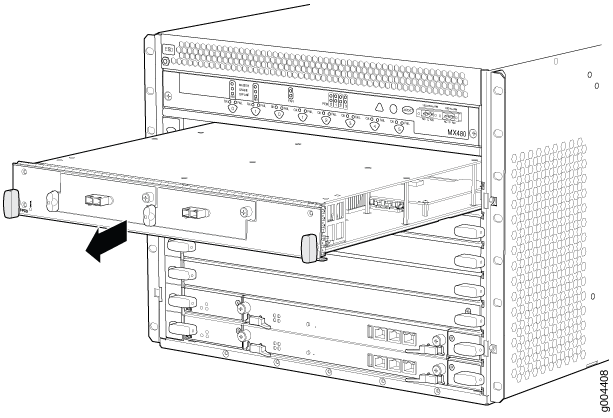
  1. Have ready a replacement FPC or FPC blank panel and an antistatic mat for the FPC. Also have ready rubber safety caps for each PIC using an optical interface on the FPC that you are removing.
  2. Attach an ESD grounding strap to your bare wrist, and connect the other end of the strap to an ESD grounding point.
  3. Label the cables connected to each PIC on the FPC so that you can later reconnect the cables to the correct PICs.
  4. Use one of the following methods to take the FPC offline:
    • Press and hold the FPC online/offline button. The green OK LED next to the button begins to blink. Hold the button down until the LED goes off. The LEDs and online/offline button for each FPC are located directly above it on the craft interface.

    • Issue the following CLI command:

      For more information about the command, see the CLI Explorer.

      Note:

      The slot number corresponds to the lowest numbered slot for which the FPC is installed.

  5. Disconnect the cables from the PICs installed in the FPC.
  6. Immediately cover each fiber-optic transceiver and the end of each fiber-optic cable with a rubber safety cap.
    Laser Warning:

    Do not look directly into a fiber-optic transceiver or into the ends of fiber-optic cables. Fiber-optic transceivers and fiber-optic cables connected to a transceiver emit laser light that can damage your eyes.

  7. Arrange the cable in the cable management brackets to prevent it from dislodging or developing stress points. Secure the cable so that it is not supporting its own weight as it hangs to the floor. Place excess cable out of the way in a neatly coiled loop. Placing fasteners on the loop helps to maintain its shape.
    CAUTION:

    Do not let fiber-optic cable hang free from the connector. Do not allow fastened loops of cable to dangle, which stresses the cable at the fastening point.

    CAUTION:

    Avoid bending fiber-optic cable beyond its minimum bend radius. An arc smaller than a few inches in diameter can damage the cable and cause problems that are difficult to diagnose.

  8. Simultaneously turn both the ejector handles counterclockwise to unseat the FPC.
  9. Grasp the handles, and slide the FPC straight out of the card cage halfway.
  10. Place one hand around the front of the FPC (the PIC housing) and the other hand under it to support it. Slide the FPC completely out of the chassis, and place it on the antistatic mat or in the electrostatic bag.
    CAUTION:

    The weight of the FPC is concentrated in the back end. Be prepared to accept the full weight—up to 18 lb (8.2 kg)—as you slide the FPC out of the chassis.

    When the FPC is out of the chassis, do not hold it by the ejector handles, bus bars, or edge connectors. They cannot support its weight.

    Do not stack FPCs on top of one another after removal. Place each one individually in an electrostatic bag or on its own antistatic mat on a flat, stable surface.

  11. If necessary, remove each installed PIC from the FPC.
  12. After you remove each PIC, immediately place it on an antistatic mat or in an electrostatic bag.
  13. If you are not reinstalling an FPC into the emptied DPC slots within a short time, install a blank DPC panel over each slot to maintain proper airflow in the card cage.
    CAUTION:

    After removing an FPC from the chassis, wait at least 30 seconds before reinserting it or inserting an FPC into a different slot.

Figure 10: Removing an FPCRemoving an FPC

Installing an MX480 FPC

An FPC takes up two DPC slots on the MX480 router. Up to three FPCs can be installed horizontally in the front of the router. The FPCs are hot-insertable and hot-removable. An empty FPC3 weighs 14 lb (6.5 kg). A fully configured FPC can weigh up to 18 lb (8.2 kg). Be prepared to accept its full weight.

To install an FPC (see Figure 11):

  1. Attach an ESD grounding strap to your bare wrist, and connect the other end of the strap to an ESD grounding point.
  2. Place the FPC on an antistatic mat.
  3. Take each PIC to be installed in the replacement FPC out of its electrostatic bag, and identify the slot on the FPC where it will be connected.
  4. Verify that each fiber-optic PIC has a rubber safety cap covering the PIC transceiver. If it does not, cover the transceiver with a safety cap.
  5. Install each PIC into the appropriate slot on the FPC.
  6. Locate the slots in the card cage in which you plan to install the FPC.
  7. Orient the FPC so that the faceplate faces you.
  8. Lift the FPC into place, and carefully align the sides of the FPC with the guides inside the card cage.
    CAUTION:

    When the FPC is out of the chassis, do not hold it by the ejector handles, bus bars, or edge connectors. They cannot support its weight.

  9. Slide the FPC all the way into the card cage until you feel resistance.
  10. Grasp both ejector handles, and rotate them clockwise simultaneously until the FPC is fully seated.
  11. If any of the PICs on the FPC connect to fiber-optic cable, remove the rubber safety cap from each transceiver and cable.
    Laser Warning:

    Do not look directly into a fiber-optic transceiver or into the ends of fiber-optic cables. Fiber-optic transceivers and fiber-optic cables connected to a transceiver emit laser light that can damage your eyes.

  12. Insert the appropriate cable into the cable connector ports on each PIC on the FPC.
  13. Arrange the cable in the cable management brackets to prevent it from dislodging or developing stress points. Secure the cable so that it is not supporting its own weight as it hangs to the floor. Place excess cable out of the way in a neatly coiled loop. Placing fasteners on the loop helps to maintain its shape.
    CAUTION:

    Do not let fiber-optic cables hang free from the connector. Do not allow the fastened loops of a cable to dangle, which stresses the cable at the fastening point.

    CAUTION:

    Do not bend a fiber-optic cable beyond its minimum bend radius. An arc smaller than a few inches in diameter can damage the cable and cause problems that are difficult to diagnose.

  14. Use one of the following methods to bring the FPC online:
    • Press and hold the FPC online/offline button until the green OK LED next to the button lights steadily, in about 5 seconds. The LEDs and online/offline button for each FPC are located directly above it on the craft interface.

    • Issue the following CLI command:

      For more information about the command, see the CLI Explorer.

    CAUTION:

    After the OK LED lights steadily, wait at least 30 seconds before removing the FPC again, removing an FPC from a different slot, or inserting an FPC in a different slot.

You can also verify correct FPC and PIC functioning by issuing the show chassis fpc and show chassis fpc pic-status commands described in Maintaining MX480 FPCs and Maintaining MX480 PICs.
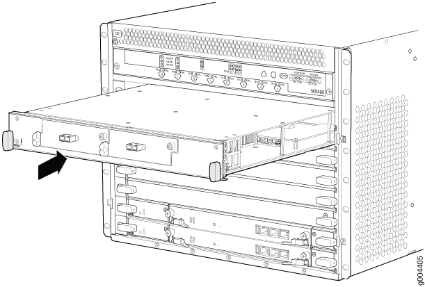
Figure 11: Installing an FPCInstalling an FPC

Maintaining MX480 MICs

Purpose

For optimum router performance, verify the condition of the MICs.

Action

On a regular basis:

  • Check the LEDs on MIC faceplates. The meaning of the LED states differs for various MICs. For more information, see the MX Series Interface Module Reference. If the MPC that houses the MIC detects a MIC failure, the MPC generates an alarm message to be sent to the Routing Engine.

  • Issue the CLI show chassis fpc pic-status command. The MIC slots in an MPC are numbered PIC 0/1 and PIC 2/3, left to right:

    For further description of the output from the command, see the CLI Explorer.

Replacing an MX480 MIC

Removing an MX480 MIC

MICs are hot-insertable and hot-removable. When you remove a MIC, the router continues to function, although the MIC interfaces being removed no longer function.

The MICs are located in the MPCs installed in the front of the router. A MIC weighs less than 2 lb (0.9 kg).

To remove a MIC (see Figure 12 and Figure 13):

  1. Place an electrostatic bag or antistatic mat on a flat, stable surface to receive the MIC. If the MIC connects to fiber-optic cable, have ready a rubber safety cap for each transceiver and cable.
  2. Attach an ESD grounding strap to your bare wrist, and connect the other end of the strap to an ESD grounding point.
  3. Use one of the following methods to take the MIC offline:
    • Press its online/offline button. Use a narrow-ended tool that fits inside the opening that leads to the button. Press and hold the button until the MIC OK/FAIL LED goes off (about 5 seconds).

    • Issue the following CLI command:

      For more information about the command, see the CLI Explorer.

  4. Label the cables connected to the MIC so that you can later reconnect each cable to the correct MIC.
  5. Disconnect the cables from the MIC. If the MIC uses fiber-optic cable, immediately cover each transceiver and the end of each cable with a rubber safety cap.
    Laser Warning:

    Do not look directly into a fiber-optic transceiver or into the ends of fiber-optic cables. Fiber-optic transceivers and fiber-optic cables connected to a transceiver emit laser light that can damage your eyes.

    CAUTION:

    Do not leave a fiber-optic transceiver uncovered, except when you are inserting or removing cable. The safety cap keeps the port clean and protects your eyes from accidental exposure to laser light.

  6. Arrange the cable to prevent it from dislodging or developing stress points. Secure the cable so that it is not supporting its own weight as it hangs to the floor. Place excess cable out of the way in a neatly coiled loop.
    CAUTION:

    Do not bend a fiber-optic cable beyond its minimum bend radius. An arc smaller than a few inches in diameter can damage the cable and cause problems that are difficult to diagnose.

  7. On the MPC, pull the ejector lever that is adjacent to the MIC you are removing away from the MPC faceplate. Pulling the ejector lever disconnects the MIC from the MPC.
    Note:

    To remove a dual-wide MIC that takes up both MIC slots, you must pull both ejector levers away from the MPC faceplate.

  8. Grasp the handles on the MIC faceplate, and slide the MIC out of the MPC card carrier. Place it in the electrostatic bag or on the antistatic mat.
  9. If you are not reinstalling a MIC into the emptied MIC slot within a short time, install a blank MIC panel over the slot to maintain proper airflow in the MPC card cage.
Figure 12: Removing a MICRemoving a MIC
Figure 13: Removing a Dual-Wide MICRemoving a Dual-Wide MIC

Installing an MX480 MIC

To install a MIC (see Figure 15):

  1. Attach an ESD grounding strap to your bare wrist, and connect the other end of the strap to an ESD grounding point.
  2. If you have used a dual-wide MIC and are now replacing it with two “single” MICs, install the septum (see Figure 14):
    1. Place the MPC on a flat surface (If necessary, remove the MPC from the router as described in Replacing an MX480 MPC).
    2. Position the septum in the center of the MPC so that it lines up with holes labeled S on the top of the MPC.
    3. Insert a screw into each of the two holes labeled S, and then tighten completely.
    4. On the bottom of the MPC, insert a screw into each of the four holes labeled S, and then tighten completely.
    5. Install the MPC as described in Replacing an MX480 MPC.
    Figure 14: Installing the SeptumInstalling the Septum
  3. If the MIC uses fiber-optic cable, verify that a rubber safety cap is over each transceiver on the faceplate. Install a cap if necessary.
  4. On the MPC, pull the ejector lever that is adjacent to the MIC you are installing away from the MPC faceplate.
  5. Align the rear of the MIC with the guides located at the corners of the MIC slot.
  6. Slide the MIC into the MPC until it is firmly seated in the MPC.
    CAUTION:

    Slide the MIC straight into the slot to avoid damaging the components on the MIC.

  7. Verify that the ejector lever is engaged by pushing it toward the MPC faceplate.
  8. If the MIC uses fiber-optic cable, remove the rubber safety cap from each transceiver and the end of each cable.
    Laser Warning:

    Do not look directly into a fiber-optic transceiver or into the ends of fiber-optic cables. Fiber-optic transceivers and fiber-optic cables connected to a transceiver emit laser light that can damage your eyes.

    CAUTION:

    Do not leave a fiber-optic transceiver uncovered, except when you are inserting or removing cable. The safety cap keeps the port clean and protects your eyes from accidental exposure to laser light.

  9. Insert the appropriate cables into the cable connectors on the MIC.
  10. Arrange each cable to prevent the cable from dislodging or developing stress points. Secure the cable so that it is not supporting its own weight as it hangs to the floor. Place excess cable out of the way in a neatly coiled loop.
    CAUTION:

    Do not let fiber-optic cables hang free from the connector. Do not allow the fastened loops of a cable to dangle, which stresses the cable at the fastening point.

    CAUTION:

    Do not bend a fiber-optic cable beyond its minimum bend radius. An arc smaller than a few inches in diameter can damage the cable and cause problems that are difficult to diagnose.

  11. Use one of the following methods to bring the MIC online:
    • Press the MIC offline/online button until the MIC OK/FAIL LED lights green.

    • Issue the following CLI command:

      For more information about the command, see the CLI Explorer.

    The normal functioning status LED confirms that the MIC is online. You can also verify correct MIC functioning by issuing the show chassis fpc pic-status command described in Maintaining MX480 MICs.

Figure 15: Installing a MICInstalling a MIC

Installing an MX480 Dual-Wide MIC

To install a dual-wide MIC (see Figure 17):

  1. Attach an ESD grounding strap to your bare wrist, and connect the other end of the strap to an ESD grounding point.
  2. Remove the septum, if necessary (see Figure 16):
    1. Place the MPC on a flat surface (if necessary, remove the MPC from the router as described in Replacing an MX480 MPC).
    2. Remove the four screws labeled S on the bottom of the MPC.
    3. Remove the two screws labeled S on the top of the MPC.
    4. Slide the septum towards you and out of the MPC.
    5. Store the septum and screws for later use.
    6. Install the MPC as described in Replacing an MX480 MPC.
    Figure 16: Removing the SeptumRemoving the Septum
  3. If the MIC uses fiber-optic cable, verify that a rubber safety cap is over each transceiver on the faceplate. Install a cap if necessary.
  4. Pull the ejector lever above both MIC slots away from the router.
  5. Align the rear of the MIC with the guides located at the corners of the MIC slot.
  6. Slide the MIC into the MIC slot until it is firmly seated in the chassis.
    CAUTION:

    Slide the MIC straight into the slot to avoid damaging the components on the MIC.

  7. Verify that the ejector levers are engaged by pushing them toward the router.
  8. If the MIC uses fiber-optic cable, remove the rubber safety cap from each transceiver and the end of each cable.
    Laser Warning:

    Do not look directly into a fiber-optic transceiver or into the ends of fiber-optic cables. Fiber-optic transceivers and fiber-optic cables connected to a transceiver emit laser light that can damage your eyes.

    CAUTION:

    Do not leave a fiber-optic transceiver uncovered, except when you are inserting or removing cable. The safety cap keeps the port clean and protects your eyes from accidental exposure to laser light.

  9. Insert the appropriate cables into the cable connectors on the MIC.
  10. Arrange each cable to prevent the cable from dislodging or developing stress points. Secure the cable so that it is not supporting its own weight as it hangs to the floor. Place excess cable out of the way in a neatly coiled loop.
    CAUTION:

    Do not let fiber-optic cables hang free from the connector. Do not allow the fastened loops of a cable to dangle, which stresses the cable at the fastening point.

    CAUTION:

    Do not bend a fiber-optic cable beyond its minimum bend radius. An arc smaller than a few inches in diameter can damage the cable and cause problems that are difficult to diagnose.

  11. Use one of the following methods to bring the MIC online:
    • Press the MIC offline/online button until the MIC OK/FAIL LED lights green.

    • Issue the following CLI command:

    The normal functioning status LED confirms that the MIC is online. You can also verify correct MIC functioning by issuing the show chassis fpc pic-status command described in Maintaining MX480 MICs.

Figure 17: Installing a Dual-Wide MICInstalling a Dual-Wide MIC

Maintaining MX480 MPCs

Purpose

The router can have up to six MPCs mounted horizontally in the card cage at the front of the chassis. For optimum router performance, verify the condition of the MPCs.

Action

On a regular basis:

  • Check the LEDs on the craft interface directly above each MPC slot. The green LED labeled OK lights steadily when an MPC is functioning normally.

  • Check the OK/FAIL LED on the MPC. If the MPC detects a failure, the MPC sends an alarm message to the Routing Engine.

  • Issue the CLI show chassis fpc command to check the status of installed MPCs. As shown in the sample output, the value Online in the column labeled State indicates that the MPC is functioning normally:

    For more detailed output, add the detail option. The following example does not specify a slot number, which is optional:

  • Issue the CLI show chassis fpc pic-status command. The MPC slots are numbered 0 through 5, bottom to top:

    For further description of the output from the command, see the CLI Explorer.

Replacing an MX480 MPC

Removing an MX480 MPC

When you remove an MPC, the router continues to function, although the MIC interfaces installed on the MPC being removed no longer function.

An MPC installs horizontally in the front of the router. The MPCs are hot-insertable and hot-removable. A fully configured MPC can weigh up to 18.35 lb (8.3 kg). Be prepared to accept its full weight.

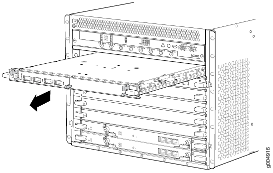
To remove an MPC (see Figure 18):
  1. Have ready a replacement MPC or DPC blank panel and an antistatic mat for the MPC. Also have ready rubber safety caps for each MIC using an optical interface on the MPC that you are removing.
  2. Attach an ESD grounding strap to your bare wrist, and connect the other end of the strap to an ESD grounding point.
  3. Label the cables connected to each MIC on the MPC so that you can later reconnect the cables to the correct MICs.
  4. Use one of the following methods to take the MPC offline:
    • Press and hold the corresponding online button on the craft interface. The green OK/FAIL LED next to the button begins to blink. Hold the button down until the LED goes off.

    • Issue the following CLI command:

      For more information about the command, see the CLI Explorer.

  5. Disconnect the cables from the MICs installed in the MPC.
    Laser Warning:

    Do not look directly into a fiber-optic transceiver or into the ends of fiber-optic cables. Fiber-optic transceivers and fiber-optic cables connected to a transceiver emit laser light that can damage your eyes.

    CAUTION:

    Do not leave a fiber-optic transceiver uncovered, except when inserting or removing a cable. The safety cap keeps the port clean and protects your eyes from accidental exposure to laser light.

    CAUTION:

    Do not bend a fiber-optic cable beyond its minimum bend radius. An arc smaller than a few inches in diameter can damage the cable and cause problems that are difficult to diagnose.

  6. If a MIC uses fiber-optic cable, immediately cover each transceiver and the end of each cable with a rubber safety cap.
  7. Arrange the disconnected cables in the cable management brackets to prevent the cables from developing stress points.
  8. Simultaneously turn both the ejector handles counterclockwise to unseat the MPC.
  9. Grasp the handles, and slide the MPC straight out of the card cage halfway.
  10. Place one hand around the front of the MPC (the MIC housing) and the other hand under it to support it. Slide the MPC completely out of the chassis, and place it on the antistatic mat or in the electrostatic bag.
    CAUTION:

    The weight of the MPC is concentrated in the back end. Be prepared to accept the full weight—up to 18.35 lb (8.3 kg)—as you slide the MPC out of the chassis.

    When the MPC is out of the chassis, do not hold it by the ejector handles, bus bars, or edge connectors. They cannot support its weight.

    Do not stack MPCs on top of one another after removal. Place each one individually in an electrostatic bag or on its own antistatic mat on a flat, stable surface.

  11. If necessary, remove each installed MIC from the MPC.
  12. After you remove each MIC, immediately place it on an antistatic mat or in an electrostatic bag.
  13. If you are not reinstalling an MPC into the emptied line card slots within a short time, install a blank DPC panel over each slot to maintain proper airflow in the card cage.
    CAUTION:

    After removing an MPC from the chassis, wait at least 30 seconds before reinserting it or inserting an MPC into a different slot.

Figure 18: Removing an MPCRemoving an MPC

Installing an MX480 MPC

An MPC installs horizontally in the front of the router. The MPCs are hot-insertable and hot-removable. A fully configured MPC can weigh up to 18.35 lb (8.3 kg). Be prepared to accept its full weight.

To install an MPC (see Figure 19):

  1. Attach an ESD grounding strap to your bare wrist, and connect the other end of the strap to an ESD grounding point.
  2. Place the MPC on an antistatic mat.
  3. Take each MIC to be installed in the replacement MPC out of its electrostatic bag, and identify the slot on the MPC where it will be connected.
  4. Verify that each fiber-optic MIC has a rubber safety cap covering the MIC transceiver. If it does not, cover the transceiver with a safety cap.
  5. Install each MIC into the appropriate slot on the MPC.
  6. Locate the slot in the card cage in which you plan to install the MPC.
  7. Orient the MPC so that the faceplate faces you.
  8. Lift the MPC into place, and carefully align the sides of the MPC with the guides inside the card cage.
    CAUTION:

    When the MPC is out of the chassis, do not hold it by the ejector handles, bus bars, or edge connectors. They cannot support its weight.

  9. Slide the MPC all the way into the card cage until you feel resistance.
  10. Grasp both ejector handles, and rotate them clockwise simultaneously until the MPC is fully seated.
  11. If any of the MICs on the MPC connect to fiber-optic cable, remove the rubber safety cap from each transceiver and cable.
    Laser Warning:

    Do not look directly into a fiber-optic transceiver or into the ends of fiber-optic cables. Fiber-optic transceivers and fiber-optic cables connected to a transceiver emit laser light that can damage your eyes.

  12. Insert the appropriate cable into the cable connector ports on each MIC on the MPC. Secure the cables so that they are not supporting their own weight. Place excess cable out of the way in a neatly coiled loop, using the cable management system. Placing fasteners on a loop helps to maintain its shape.
    CAUTION:

    Do not let fiber-optic cables hang free from the connector. Do not allow the fastened loops of a cable to dangle, which stresses the cable at the fastening point.

    CAUTION:

    Do not bend a fiber-optic cable beyond its minimum bend radius. An arc smaller than a few inches in diameter can damage the cable and cause problems that are difficult to diagnose.

  13. Use one of the following methods to bring the MPC online:
    • Press and hold the corresponding MPC online button on the craft interface until the green OK/FAIL LED next to the button lights steadily, in about 5 seconds.

    • Issue the following CLI command:

      For more information about the command, see the CLI Explorer.

    CAUTION:

    After the OK/FAIL LED lights steadily, wait at least 30 seconds before removing the MPC again, removing an MPC from a different slot, or inserting an MPC in a different slot.

You can also verify correct MPC and MIC functioning by issuing the show chassis fpc and show chassis fpc pic-status commands described inMaintaining MX480 MPCs and Maintaining MX480 MICs.
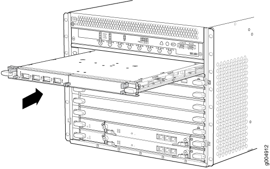
Figure 19: Installing an MPCInstalling an MPC

Maintaining MX480 PICs

Purpose

For optimum router performance, verify the condition of the PICs.

Action

On a regular basis:

  • Check the LEDs on PIC faceplates. The meaning of the LED states differs for various PICs. For more information, see the MX Series Interface Module Reference. If the FPC that houses the PIC detects a PIC failure, the FPC generates an alarm message to be sent to the Routing Engine.

  • Issue the CLI show chassis fpc pic-status command. The PIC slots in an FPC are numbered from 0 through 1, left to right:

    For further description of the output from the command, see the CLI Explorer.

Replacing an MX480 PIC

Removing an MX480 PIC

PICs are hot-insertable and hot-removable. When you remove a PIC, the router continues to function, although the PIC interfaces being removed no longer function.

The PICs are located in the FPCs installed in the front of the router. A PIC weighs less than 2 lb (0.9 kg).

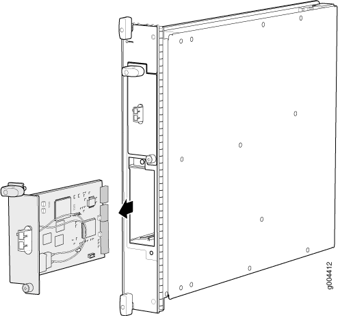
To remove a PIC (see Figure 20):
  1. Place an electrostatic bag or antistatic mat on a flat, stable surface to receive the PIC. If the PIC connects to fiber-optic cable, have ready a rubber safety cap for each transceiver and cable.
  2. Attach an ESD grounding strap to your bare wrist, and connect the other end of the strap to an ESD grounding point.
  3. Use one of the following methods to take the PIC offline:
    • Press its online/offline button. For a PIC installed in FPC3, use a narrow-ended tool that fits inside the opening that leads to the button. Press and hold the button until the PIC LED goes off (about 5 seconds).

    • Issue the following CLI command:

      For more information about the command, see the CLI Explorer.

  4. Label the cables connected to the PIC so that you can later reconnect each cable to the correct PIC.
  5. Disconnect the cables from the PIC. If the PIC uses fiber-optic cable, immediately cover each transceiver and the end of each cable with a rubber safety cap.
    Laser Warning:

    Do not look directly into a fiber-optic transceiver or into the ends of fiber-optic cables. Fiber-optic transceivers and fiber-optic cables connected to a transceiver emit laser light that can damage your eyes.

    CAUTION:

    Do not leave a fiber-optic transceiver uncovered, except when you are inserting or removing cable. The safety cap keeps the port clean and protects your eyes from accidental exposure to laser light.

  6. Arrange the cable in the cable management brackets to prevent it from dislodging or developing stress points. Secure the cable so that it is not supporting its own weight as it hangs to the floor. Place excess cable out of the way in a neatly coiled loop. Placing fasteners on the loop helps to maintain its shape.
    CAUTION:

    Do not let fiber-optic cables hang free from the connector. Do not allow the fastened loops of a cable to dangle, which stresses the cable at the fastening point.

    CAUTION:

    Do not bend a fiber-optic cable beyond its minimum bend radius. An arc smaller than a few inches in diameter can damage the cable and cause problems that are difficult to diagnose.

  7. For an FPC3 PIC, loosen the captive screw at the bottom of the PIC faceplate, then twist the ejector handle at the top of the faceplate counterclockwise to unseat the PIC.
  8. Slide the PIC out of the FPC card carrier and place it in the electrostatic bag or on the antistatic mat.
  9. If you are not reinstalling a PIC into the emptied PIC slot within a short time, install a blank PIC panel over the slot to maintain proper airflow in the FPC card cage.
Figure 20: Removing a PICRemoving a PIC

Installing an MX480 PIC

To install a PIC (see Figure 21):

  1. Attach an ESD grounding strap to your bare wrist, and connect the other end of the strap to an ESD grounding point.
  2. If the PIC uses fiber-optic cable, verify that a rubber safety cap is over each transceiver on the faceplate. Install a cap if necessary.
  3. Align the notches in the connector at the rear of the PIC with the notches in the PIC slot in the FPC and then slide the PIC in until it lodges firmly in the FPC.
    CAUTION:

    Slide the PIC straight into the slot to avoid damaging the components on the bottom of the PIC.

  4. For an FPC3 PIC, turn the ejector handle at the top of the PIC faceplate clockwise, then tighten the captive screw at the bottom of the faceplate to secure the PIC in the FPC.
  5. If the PIC uses fiber-optic cable, remove the rubber safety cap from each transceiver and the end of each cable.
    Laser Warning:

    Do not look directly into a fiber-optic transceiver or into the ends of fiber-optic cables. Fiber-optic transceivers and fiber-optic cables connected to a transceiver emit laser light that can damage your eyes.

    CAUTION:

    Do not leave a fiber-optic transceiver uncovered, except when you are inserting or removing cable. The safety cap keeps the port clean and protects your eyes from accidental exposure to laser light.

  6. Insert the appropriate cables into the cable connectors on the PIC.
  7. Arrange the cable in the cable management brackets to prevent it from dislodging or developing stress points. Secure the cable so that it is not supporting its own weight as it hangs to the floor. Place excess cable out of the way in a neatly coiled loop. Placing fasteners on the loop helps to maintain its shape.
    CAUTION:

    Do not let fiber-optic cables hang free from the connector. Do not allow the fastened loops of a cable to dangle, which stresses the cable at the fastening point.

    CAUTION:

    Do not bend a fiber-optic cable beyond its minimum bend radius. An arc smaller than a few inches in diameter can damage the cable and cause problems that are difficult to diagnose.

  8. Use one of the following methods to bring the PIC online:
    • Press the PIC offline/online button until the PIC LED lights green. For a PIC installed in an FPC2 or FPC3, use a narrow-ended tool that fits inside the opening that leads to the button.

    • Issue the following CLI command:

      For more information about the command, see the CLI Explorer.

    The normal functioning status LED confirms that the PIC is online. You can also verify correct PIC functioning by issuing the show chassis fpc pic-status command described in Maintaining MX480 PICs.

Figure 21: Installing a PICInstalling a PIC

Replacing an MX480 AS MLC

Removing an MX480 AS MLC

When you remove an Application Services Modular Line Card (AS MLC), the router continues to function, although the modular cards (AS MXC and AS MSC) installed on the AS MLC being removed no longer function.

Up to five AS MLCs can be installed horizontally in the front of the MX480 router. The AS MLCs are hot-insertable and hot-removable. An empty AS MLC weighs 10.5 lb  (4.76 kg). A fully configured AS MLC can weigh up to 15.27 lb  (6.93 kg). Be prepared to accept its full weight.

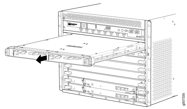
To remove an AS MLC (see Figure 22):
  1. Have ready a replacement AS MLC or an AS MLC blank panel and an antistatic mat for the AS MLC.
  2. Attach an ESD grounding strap to your bare wrist, and connect the other end of the strap to an ESD grounding point.
  3. Use one of the following methods to take the AS MLC offline:
    • Press and hold the AS MLC online/offline button. The green OK LED next to the button begins to blink. Hold the button down until the LED goes out. The online/offline button for each AS MLC is located directly above it on the craft interface.

    • Issue the following CLI command:

      For more information about the command, see the CLI Explorer.

      Note:

      The slot number corresponds to the lowest numbered slot for which the AS MLC is installed.

  4. Simultaneously turn both the ejector handles counterclockwise to unseat the AS MLC.
  5. Grasp the handles, and slide the AS MLC straight out of the card cage halfway.
  6. Place one hand around the front of the AS MLC (the modular card housing) and the other hand under it to support it. Slide the AS MLC completely out of the chassis, and place it on the antistatic mat or in the electrostatic bag.
    CAUTION:

    The weight of the AS MLC is concentrated in the back end. Be prepared to accept the full weight—up to 15.27 lb  (6.93 kg)—as you slide the AS MLC out of the chassis.

    When the AS MLC is out of the chassis, do not hold it by the ejector handles, bus bars, or edge connectors. They cannot support its weight.

    Do not stack AS MLCs on top of one another after removal. Place each one individually in an electrostatic bag or on its own antistatic mat on a flat, stable surface.

  7. If necessary, remove each installed AS MSC and AS MXC from the AS MLC.
  8. After you remove each modular card, immediately place it on an antistatic mat or in an electrostatic bag.
  9. If you are not reinstalling an AS MLC into the emptied slots within a short time, install a blank AS MLC panel over each slot to maintain proper airflow in the card cage.
    CAUTION:

    After removing an AS MLC from the chassis, wait at least 30 seconds before reinserting it or inserting an AS MLC into a different slot.

Figure 22: Removing an AS MLCRemoving an AS MLC

Installing an MX480 AS MLC

You can install up to five Application Services Modular Line Cards (AS MLCs) horizontally in the front of the MX480 router. The AS MLCs are hot-insertable and hot-removable. An empty AS MLC weighs 10.5 lb  (4.76 kg). A fully configured AS MLC can weigh up to 15.27 lb  (6.93 kg). Be prepared to accept its full weight.

To install an AS MLC (see Figure 23):

  1. Attach an ESD grounding strap to your bare wrist, and connect the other end of the strap to an ESD grounding point.
  2. Place the AS MLC on an antistatic mat.
  3. Take the AS MSC and AS MXC (the modular cards) to be installed in the AS MLC out of its electrostatic bag. The AS MSC must be inserted in the left slot and the AS MXC in the right slot.
  4. Install the AS MSC and AS MXC into the appropriate slot on the AS MLC.
  5. Locate the slots in the card cage in which you plan to install the AS MLC.
  6. Orient the AS MLC so that the faceplate faces you.
  7. Lift the AS MLC into place, and carefully align the sides of the AS MLC with the guides inside the card cage.
    CAUTION:

    When the AS MLC is out of the chassis, do not hold it by the ejector handles, bus bars, or edge connectors. They cannot support its weight.

  8. Slide the AS MLC all the way into the card cage until you feel resistance.
  9. Grasp both ejector handles, and rotate them clockwise simultaneously until the AS MLC is fully seated.
  10. Use one of the following methods to bring the AS MLC online:
    • Press and hold the AS MLC online/offline button until the green OK LED next to the button lights steadily, in about 5 seconds. The LEDs and online/offline button for each AS MLC are located above it on the craft interface.

    • Issue the following CLI command:

      For more information about the command, see the CLI Explorer.

    CAUTION:

    After the OK LED lights steadily, wait at least 30 seconds before removing the AS MLC again, removing an AS MLC from a different slot, or inserting an AS MLC in a different slot.

You can also verify correct AS MLC and AS MSC or AS MXC functioning by issuing the show chassis fpc and show chassis fpc pic-status.
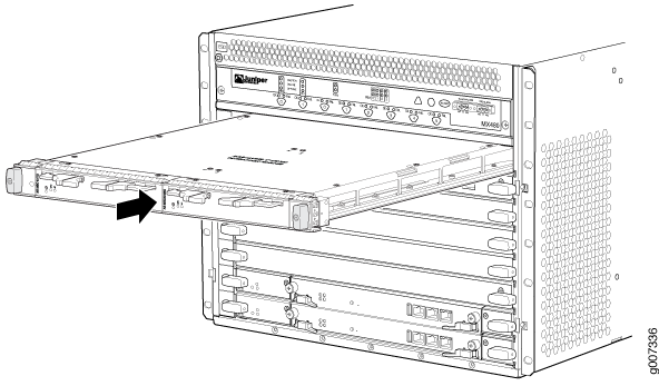
Figure 23: Installing an AS MLCInstalling an AS MLC

Replacing an MX480 AS MSC

Removing an MX480 AS MSC

AS MSCs are hot-insertable and hot-removable. When you remove an AS MSC, the router continues to function.

The AS MSCs are located in the AS MLCs installed in the front of the router. An AS MSC weighs 1.4 lb (0.6 kg).

To remove an AS MSC (see Figure 24):
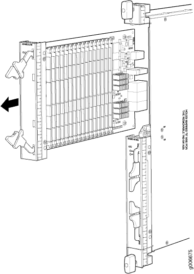
  1. Place an electrostatic bag or antistatic mat on a flat, stable surface to receive the AS MSC.
  2. Attach an ESD grounding strap to your bare wrist, and connect the other end of the strap to an ESD grounding point.
  3. Use one of the following methods to take the AS MSC offline:
    • Press its online/offline button. Use a narrow-ended tool that fits inside the opening that leads to the button. Press and hold the button until the AS MSC LED goes out (about 5 seconds).

    • Issue the following CLI command:

      For more information about the command, see the CLI Explorer.

  4. Slide the AS MSC out of the AS MLC card carrier by pulling the handles, and place it in the electrostatic bag or on the antistatic mat.
  5. If you are not reinstalling an AS MSC into the emptied AS MSC slot within a short time, install a blank AS MSC panel over the slot to maintain proper airflow in the AS MLC card cage.
Figure 24: Removing an AS MSCRemoving an AS MSC

Installing an MX480 AS MSC

To install an AS MSC (see Figure 25):

  1. Attach an ESD grounding strap to your bare wrist, and connect the other end of the strap to an ESD grounding point.
  2. Align the notches in the connector at the rear of the AS MSC with the notches in the AS MSC slot (slot 0—the top slot in the AS MLC ), and then slide the AS MSC in until it lodges firmly in the AS MLC.
    CAUTION:

    Slide the AS MSC straight into the slot to avoid damaging the components on the bottom of the AS MSC.

  3. Use one of the following methods to bring the AS MSC online:
    • Press the AS MSC offline/online button until the LED light turns green.

    • Issue the following CLI command:

      For more information about the command, see the CLI Explorer.

    The normal functioning status LED confirms that the AS MSC is online. You can also verify correct AS MSC functioning by issuing the show chassis fpc pic-status.

Figure 25: Installing an AS MSCInstalling an AS MSC

Replacing an MX480 AS MXC

Removing an MX480 AS MXC

AS MXCs are hot-insertable and hot-removable. When you remove an AS MXC, the router continues to function.

The AS MXCs are located in the AS MLCs installed in the front of the router. An AS MXC weighs 1.4 lb (0.6 kg).

To remove an AS MXC (see Figure 26):
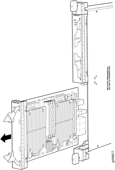
  1. Place an electrostatic bag or antistatic mat on a flat, stable surface to receive the AS MXC.
  2. Attach an ESD grounding strap to your bare wrist, and connect the other end of the strap to an ESD grounding point.
  3. Use one of the following methods to take the AS MXC offline:
    • Press its online/offline button. Use a narrow-ended tool that fits inside the opening that leads to the button. Press and hold the button until the AS MXC LED goes out (about 5 seconds).

    • Issue the following CLI command:

      For more information about the command, see the CLI Explorer.


  4. Slide the AS MXC out of the AS MLC card carrier by pulling the handles, and place it in the electrostatic bag or on the antistatic mat.
  5. If you are not reinstalling an AS MXC into the emptied AS MXC slot within a short time, install a blank AS MXC panel over the slot to maintain proper airflow in the AS MLC card cage.
Figure 26: Removing an AS MXCRemoving an AS MXC

Installing an MX480 AS MXC

To install an AS MXC (see Figure 27):

  1. Attach an ESD grounding strap to your bare wrist, and connect the other end of the strap to an ESD grounding point.
  2. Align the notches in the connector at the rear of the AS MXC with the notches in the AS MXC slot (slot 1—the bottom slot in the AS MLC), and then slide the AS MXC in until it lodges firmly in the AS MLC.
    CAUTION:

    Slide the AS MXC straight into the slot to avoid damaging the components on the bottom of the AS MXC.

  3. Use one of the following methods to bring the AS MXC online:
    • Press the AS MXC offline/online button until the LED light turns green.

    • Issue the following CLI command:

      For more information about the command, see the CLI Explorer.

    The normal functioning status LED confirms that the AS MXC is online. You can also verify correct AS MXC functioning by issuing the show chassis fpc pic-status command.

Figure 27: Installing an AS MXCInstalling an AS MXC

Maintaining Cables That Connect to MX480 DPCs, MPCs, MICs, or PICs

Purpose

For optimum router performance, verify the condition of the cables that connect to the DPCs, MPCs, MICs, or PICs.

Action

On a regular basis:

  • Use the cable management brackets to support cables and prevent cables from dislodging or developing stress points.

  • Place excess cable out of the way in the cable management brackets. Do not allow fastened loops of cable to dangle from the connector or cable management brackets, because this stresses the cable at the fastening point. Putting fasteners on the loops helps to maintain their shape.

  • Keep the cable connections clean and free of dust and other particles, which can cause drops in the received power level. Always inspect cables and clean them if necessary before connecting an interface.

  • Label both ends of the cables to identify them.

The following guidelines apply specifically to fiber-optic cables:

  • When you unplug a fiber-optic cable, always place a rubber safety plug over the transceiver on the faceplate and on the end of the cable.

  • Anchor fiber-optic cables to avoid stress on the connectors. Be sure to secure fiber-optic cables so that they do not support their own weight as they hang to the floor. Never let fiber-optic cable hang free from the connector.

  • Avoid bending fiber-optic cable beyond its bend radius. An arc smaller than a few inches can damage the cable and cause problems that are difficult to diagnose.

  • Frequent plugging and unplugging of fiber-optic cable into and out of optical instruments can cause damage to the instruments that is expensive to repair. Instead, attach a short fiber extension to the optical equipment. Any wear and tear due to frequent plugging and unplugging is then absorbed by the short fiber extension, which is easy and inexpensive to replace.

  • Keep fiber-optic cable connections clean. Small microdeposits of oil and dust in the canal of the transceiver or cable connector could cause loss of light, reducing signal power and possibly causing intermittent problems with the optical connection.

    To clean the transceivers, use an appropriate fiber-cleaning device, such as RIFOCS Fiber Optic Adaptor Cleaning Wands (part number 946). Follow the directions for the cleaning kit you use.

    After you clean an optical transceiver, make sure that the connector tip of the fiber-optic cable is clean. Use only an approved alcohol-free fiber-optic cable cleaning kit, such as the Opptex Cletop-S Fiber Cleaner. Follow the directions for the cleaning kit you use.