Fast Track to Rack Installation and Power
This procedure guides you through the steps to install your MX480 router in a four-post rack or cabinet using a mechanical lift and connect it to AC power.
Install the MX480 Router for a Rack or Cabinet
You can install your MX480 router in a four-post rack or cabinet, or an open-frame rack. Before you install the router, install the mounting shelf that is included in the shipping container.
We recommend that you install the mounting shelf because the weight of a fully loaded chassis can be up to 128lb (58.1kg).
We'll walk you through the steps to install the router in a four-post rack or cabinet using a mechanical lift. If you cannot use a mechanical lift to install the router (recommended), you can install it manually. See Installing the MX480 Chassis in the Rack Manually.
Before you install, review the following:
If you're installing more than one router in a rack, install the routers from the bottom up.
Before mounting the router in a rack, have a qualified technician verify that the rack is strong enough to support the router's weight and is adequately supported at the installation site.
Install the MX480 Router Mounting Shelf
To install the mounting shelf on the front rails of a four-post rack or cabinet, or the rails of an open-frame rack:
-
Partially insert the remaining screws into the open holes in each flange of
the small shelf.
Figure 1: Installing the Front-Mounting Hardware for a Four-Post Rack or Cabinet
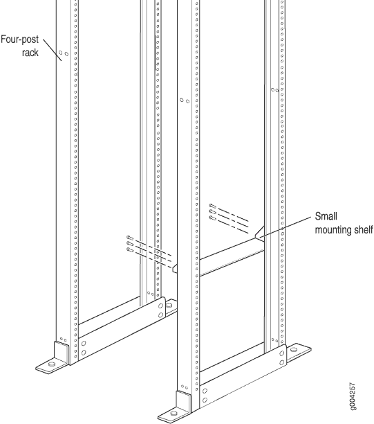 Figure 2: Installing the Mounting Hardware for an Open-Frame Rack
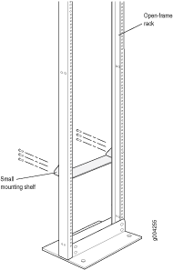
Connect to Power
Now that you've mounted your router in the rack, you're ready to ground your router and connect it to AC power.
Ground the MX480 Router
You ground the router by connecting a grounding cable to earth ground and then attaching it to the chassis grounding points by using two screws. To connect the grounding cable:
Attach an ESD grounding strap to your bare wrist, and connect the other end of the strap to an approved site ESD grounding point. See the instructions for your site.
Connect the grounding cable to a proper earth ground.
Verify that a licensed electrician has attached the cable lug provided with the router to the grounding cable.
Make sure that grounding surfaces are clean and brought to a bright finish before grounding connections are made.
Attach an ESD grounding strap to your bare wrist, and connect the other end of the strap to an ESD grounding point.
Place the grounding cable lug over the grounding points. The grounding point is sized for UNC 1/4-20 bolts.
Secure the grounding cable lug to the grounding points, first with the washers, then with the screws.
Verify that the grounding cabling is correct, that the grounding cable does not touch or block access to router components, and that it does not drape where people could trip on it.
Connect Power to an AC Router with Normal-Capacity Power Supplies
Depending on your configuration, your router uses either normal-capacity or high-capacity AC or DC power supplies. Perform the appropriate procedures for each power supply in your router.
Locate the power cords, which should have a plug appropriate for your geographical location.
Move the power switch on the power supply faceplate to the standby position.
Insert the power cord plug into an external AC power source receptacle.
Note:Each power supply must be connected to a dedicated AC power feed and a dedicated customer site circuit breaker. We recommend that you use a 15 A (250 VAC) minimum, or as permitted by local code.
Dress the power cord appropriately. Verify that the power cord does not block the air exhaust and access to router components, or drape where people could trip on it.