QFX5130 Management Panel
QFX5130-32CD/QFX5130E-32CD Management Panel Overview
The management panel of the QFX5130-32CD/QFX5130E-32CD is divided in two sections, with the port panel in between these sections.

Chassis status LEDs
32 high-speed ports-QSFP-DD cages
RJ-45 management port (100 Mbps/1000 Mbps/10000 Mbps)
RJ-45 console port
USB port (USB 2.0/3.0 standard)
Reset button (do not use unless directed by JTAC)
Chassis serial number pull-out
10-Gigabit Ethernet (GbE) ports–SFP+ cages
Output connectors (10 MHz and 1 PPS)
Electrostatic discharge (ESD) grounding point
QFX5130-32CD/QFX5130E-32CD Chassis Status LEDs
You can find LEDs on these management ports:
show chassis lcd.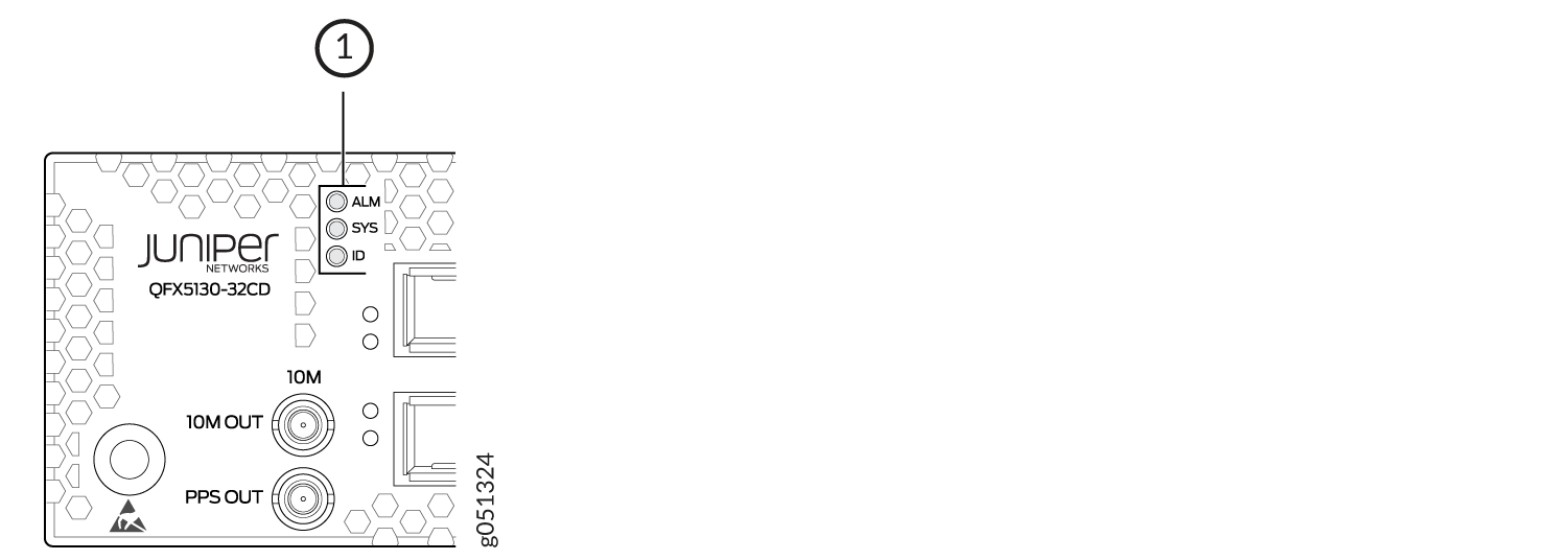
1 — Chassis status LEDs |
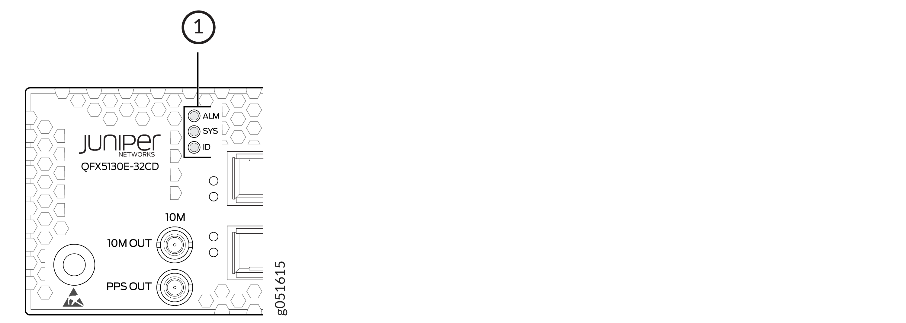
1 — Chassis status LEDs |
Name |
Color |
State |
Description |
|---|---|---|---|
ALM–Alarm |
Unlit |
Off |
There is no alarm. |
Red |
On steadily |
A major hardware fault has occurred, such as a temperature alarm, power failure, or media failure. You need to to take remedial action based on the nature of the alarm. |
|
Amber |
On steadily |
A minor system level alarm has occurred, such as a software error or a missing rescue configuration. You would need to to take remedial action based on the nature of the alarm. |
|
SYS–System |
Unlit |
Off |
The device is powered off or rebooted. |
Green |
On steadily |
Junos OS Evolved is loaded on the device, or the device is halted. |
|
ID–Identification |
Unlit |
Off |
The beacon feature is not enabled on the switch. Enable this feature by using the |
Blue |
Blinking |
The beacon feature is enabled on the switch. Disable this feature by using the |
|
Tip:
To find the status of the beacon, use the user@host> show chassis beacon fpc 0
FPC 0 OFF |
|||
When you reboot the device or the device is halted, the previous state of chassis status LED for alarms (Red/Amber/Unlit) is retained on reboot/restart.
The management port on a QFX5130-32CD/QFX5130E-32CD has two LEDs—one indicates link status and the other link activity. See Figure 5. The management port is labeled MGMT for 10/100/1000BASE-T connections.
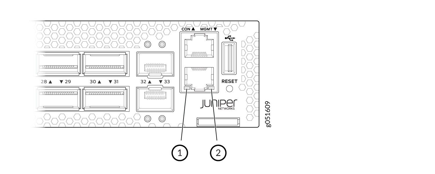
1 — Status LED | 2 — Activity LED |
Table 2 describes the management port LEDs.
LED |
Color |
State |
Description |
|---|---|---|---|
Link/Activity |
Unlit |
Off |
No link is established. There is a fault or the link is down. |
Green |
On steadily |
A link is established, but there is no link activity. |
|
Blinking or flickering |
A link is established, and there is link activity. |
||
Status |
Unlit |
Off |
Either the port speed is 10 Mbps or the link is down. |
Amber |
On steadily |
The port speed is 1 Gbps. |
|
Amber |
Flashing |
The port speed is 100 Mbps. |
QFX5130-48C Management Panel Overview
The management panel of QFX5130-48C/QFX5130-48CM is located on the rear side of the switch.

1 — ESD point | 7 — RJ-45 management port |
2 — Clock input and output connectors [10 megahertz (MHz) and 1 pulses per second (PPS)] | 8 — RJ-45 console port |
3 — SFP+ port | 9 — USB slot |
4 — Fans | 10 — Chassis status LEDs |
5 — Power supply | 11 — Reset button |
6 — SFP+ port |
To access the pinhole reset without any hindrance, you must use a USB drive with a maximum width of 16.5 mm. For reference, SanDisk Cruzer Force, HP v207 USB drives.
QFX5130-48C Chassis Status LEDs
QFX5130-48C/QFX5130-48CM has three LEDs that indicate the system status. You can find these LEDs on the left of the small form-factor pluggable (SFP) ports.

1 — Chassis alarm or fault | 3 — ID—Identification |
2 — System status |
Table 3 describes the various states of network port LEDs for the SFP+ ports.
| Name | Color | State | Description |
|---|---|---|---|
| ALM–Alarm | Unlit | Off | The switch is halted or there is no alarm. |
| Red | On steadily | A major hardware fault has occurred, such as a temperature alarm, power failure, or media failure. You would need to to take remedial action based on the nature of the alarm. | |
| Yellow | On steadily | A minor system level alarm has occurred, such as a software error or a missing rescue configuration. You would need to to take remedial action based on the nature of the alarm. | |
| Amber (Red and Yellow) | Blinking | A major and minor system-level alarm has occurred and requires immediate action. | |
| SYS–System | Unlit | Off | The device is powered off or halted. |
| Green | Blinking | The Junos OS Evolved software is getting loaded on the device. This LED is also activated when the system shutdown is in progress. | |
| Green | On steadily | The Junos OS Evolved software is loaded on the device, and the system is operational. | |
| ID–Identification | Unlit | Off | The beacon feature is not enabled on the switch. Enable this feature by using the request chassis beacon fpc 0 on operational CLI command. |
| Blue | Blinking | The beacon feature is enabled on the switch. Disable this feature by using the request chassis beacon fpc 0 off operational CLI command. |
|
Tip:
To find the status of the beacon, use the user@host> show chassis beacon fpc 0
FPC 0 OFF |
|||
You can remotely view the colors of the three LEDs through the CLI by issuing the operational mode command show chassis led.
This is a sample output.
user@host> show chassis led
 -----------------------------------
LEDs status:
    Alarm LED : Blinking Red/Yellow
    Beacon LED: Off
    System LED: Green

Interface               STATUS LED      LINK/ACTIVITY LED
---------------------------------------------------------
et-0/0/0                N/A             Off
et-0/0/1                N/A             Off
et-0/0/2                N/A             Off
et-0/0/3                N/A             Off
et-0/0/4                N/A             Off
et-0/0/5                N/A             Off
et-0/0/6                N/A             Off
et-0/0/7                N/A             Off
et-0/0/8                N/A             Off
et-0/0/9                N/A             Off
et-0/0/10               N/A             Green
QFX5130-48C Network LEDs
In an unchannelized port, the port link status for the corresponding top and bottom rows is shown above the top row of ports.
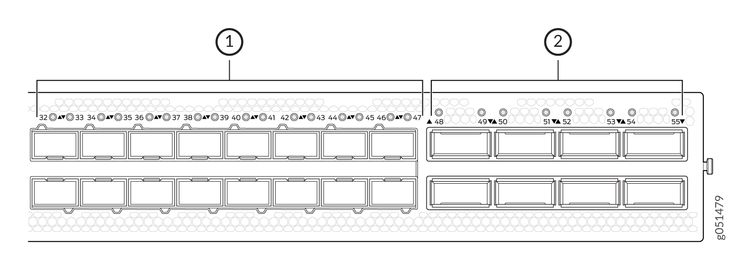
1 — LEDs that indicate status and channelizationfor each SFP56-DD port. | 2 — LEDs that indicate status and channelization for each QSFP56-DD port. |
Each port has an individual status LED. The LEDs are positioned in a row above the top row of network ports. A network port status LED has four states, including the state when the device is turned off.
Off
Green
Amber
Red
| Transceiver Inserted | Normal | Breakout Cable Configuration State | Explicitly Disabled | Port State | Port Location On | Lane Display |
|---|---|---|---|---|---|---|
| Any | Green | No breakout | No | Up | Blinking green | Not applicable |
| Yes | Red | No breakout | No | Down because of transceiver hardware failure | Blinking red | Not applicable |
| Yes | Off | No breakout | No | Down because of a loss of signal (LOS) OR Down because of loss of signal (LOS) detection | Blinking green | Not applicable |
| Any | Amber | No breakout | No | Down because of any fault except LOS and transceiver hardware failure | Blinking amber | Not applicable |
| Any | Amber | No breakout | Yes | Port disabled on the CLI | Blinking amber | Not applicable |
| No | Off | Any | No | Anything except disabled port, but no transciever is present | Blinking green | Not applicable |
| Any | Green | Breakout | No | All breakout ports are up | Blinking green | Blinking green |
| Yes | Red | Breakout | No | Hardware failure because of transceiver initialization error at the port level | Blinking red | Blinking red |
| Yes | Off | Breakout | No | All breakout ports down with an LOS. | Blinking green | Blinking green |
| Any | Amber | Breakout | Any | Any state other than the states described in this table. | Blinking amber | Blinking amber |
The management port on a QFX5130-48C has two LEDs—one indicates link status and the other link activity. The management port is labeled MGMT for 10/100/1000BASE-T connections. See Figure 9.
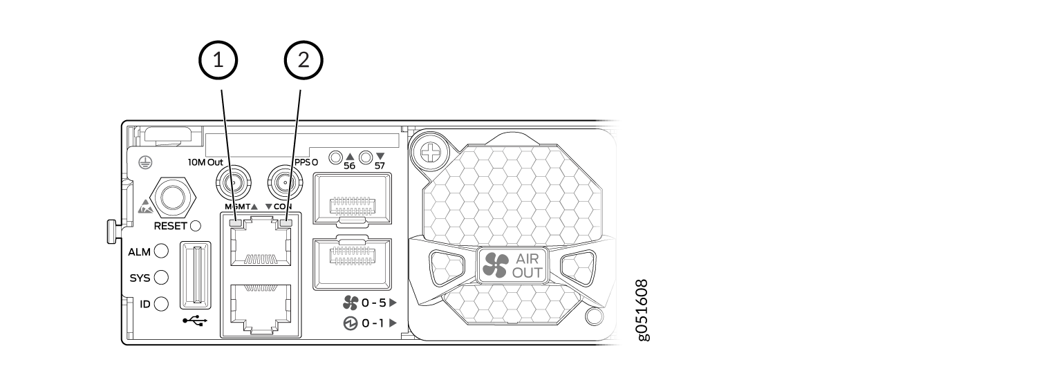
1 — Status LED | 2 — Activity LED |
Table 5describes the management port LEDs on a QFX5130-48C switch.
LED |
Color |
State |
Description |
|---|---|---|---|
Link/Activity |
Unlit |
Off |
No link is established. There is a fault or the link is down. |
Green |
On steadily |
A link is established, but there is no link activity. |
|
Blinking or flickering |
A link is established, and there is link activity. |
||
Status |
Unlit |
Off |
Either the port speed is 10 Mbps or the link is down. |
Amber |
On steadily |
The port speed is 1 Gbps. |
|
Amber |
Flashing |
The port speed is 100 Mbps. |
