JNU Topology for CSDS
Learn about JNU topology and nodes in Connected Security Distributed Services (CSDS) architecture.
Junos Node Unifier (JNU) is a single touchpoint management solution that manages the network devices in Connected Security Distributed Services (CSDS) Architecture. This solution provides a single point from where you can centrally configure the network devices that run Junos OS.
JNU Nodes
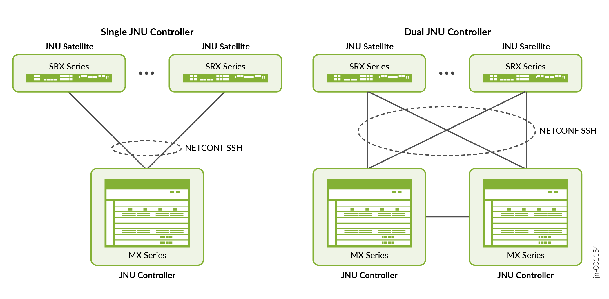
Figure 1 shows the JNU topology and its components.
-
JNU controller—A centralized entity that presents a unified CLI view of multiple network devices such as JNU satellites in the CSDS topology. This node runs the jnud process in controller mode. In addition to a single-controller setup, the JNU topology supports dual-controller setup to provide active/active high availability.
-
JNU satellite—JNU satellites are the physical or virtual network devices that operate under the control of JNU controller. Each node runs the jnud process in satellite mode.
The connectivity between the JNU nodes is established using the CSDS management network, eliminating the need for a separate network. During JNU configuration, the device creates jnuadmin user credentials. The controller and satellites use these credentials to communicate. The communication channel is secure NETCONF over SSH connection. The controller learns each satellite's device management schema. Device management schema is a unique data model that is specific to a network device. It describes the complete configuration and operational capabilities of the device. After you configure JNU, you can access all the satellite's schema from the controller and manage the nodes centrally from the controller.
JNU Topology Considerations
In a multinode setup such as the CSDS architecture:
-
The MX Series router running the jnud process acts as the JNU controller. We support a single touchpoint management solution with a single controller or with dual controllers.
-
The SRX Series Firewalls, vSRX Virtual Firewalls (vSRX), and Junos Device Manager (JDM) running the jnud process act as JNU satellites.
-
The external Ubuntu server that hosts the JDM and vSRX instances is not part of the JNU topology.
-
You must run the same Junos OS release on the controller and the satellite nodes.
JNU Deployment Process
The following procedure describes the JNU deployment process:
Configure the MX Series router as the controller. Note that you must configure the controller role on both the Routing Engines.
Configure SRX Series Firewalls, vSRX Virtual Firewalls, and a JDM container as satellites.
When satellites join the controller,
Satellites push their schema to the controller during the initial synchronization. The controller also learns the version and model of the satellite as part of the initial synchronization. A satellite has 30 minutes to synchronize with the controller, making 60 attempts at 30-second intervals. If synchronization fails, you can run the command
request jnu satellite syncon the satellite, to manually perform initial synchronization.The output of the operational command
show chassis jnu
                  satellites
lists all the satellites managed by the controller, including the JDM. Although you add JDM as a satellite, JDM doesn’t send its configuration to the controller during the initial synchronization, unlike the other satellites. But you can run JDM-specific operational commands using the controller.As the controller comes with dual Routing Engines, the controller synchronizes the other Routing Engine with the schema details.
In a dual-controller setup, the satellites perform initial synchronization with both the controllers. A satellite fetches the controller IP address from the
[edit chassis
                  jnu-management other-controller controller-ip-address]
hierarchy level and then sends the schema to both the controllers. If the other controller is unreachable, the commit fails.Controller merges the satellite's command hierarchy with its own command hierarchy, but excludes the satellite’s configuration schema. The controller and the satellites separately maintain their configuration schemas.
The controller dynamically learns the different versions of the schema that are running on each satellite.
Note:The satellites must join the controller without leaving any uncommitted changes on the controller. Avoid running configuration commands during the satellite's joining and upgrade processes. Use the operational command
show chassis jnu satellitesto check the status of the satellites before you run the configuration commands.Avoid running commands directly on the satellites after the satellites join the JNU topology, as the satellite's configuration might be overwritten by commits from the controller.
You cannot perform XML subtree filtering of configuration for satellites from the controller.
- Controller does the subsequent management of satellites. In the controller, you can run the Junos OS commands specific for the network devices that are added as satellites.