ON THIS PAGE
Example: Configuring the MAC Address of an IRB Interface
This example shows how to configure the media access control (MAC) address of an integrated routing and bridging (IRB) interface for devices with Modular Port Concentrator (MPC) cards . An IRB interface is a Layer 3 routing interface that is used in a bridge domain or virtual private LAN service (VPLS) routing.
Requirements
This example requires MX Series routers with MPC cards.
Overview
The assignment of MAC addresses to IRB logical interfaces is supported . The IRB logical interfaces provide support for simultaneous Layer 2 bridging and Layer 3 routing within the same bridge domain. Packets that arrive on an interface of the bridge domain are either switched or routed, based on the destination MAC address of the packet. The packets with the router’s Layer 2 virtual MAC address, which is manually configured, are switched to Layer 2 interfaces.
Configuring a MAC address of an IRB logical interface allows the use of a transparent firewall between two VLANs on the same switch. When both VLANs are on the same subnet and traffic from one VLAN needs to go through the firewall to the host on the other VLAN, then the VLAN tag is changed to communicate with the host on the other VLAN.
Before the introduction of this feature, if the MAC address of an IRB logical interface was the same for both VLANs, the firewall dropped the traffic. This new feature allows you to configure distinct MAC addresses for different VLANs, which facilitates the exchange of traffic between two VLANs on the same switch.
In case of VPLS multihoming, if there is a failover of the primary provider edge (PE) router to a secondary PE router, the MAC address of an IRB changes. The hosts connected to the customer edge (CE) router must change their Address Resolution Protocol (ARP) for IRB’s IP and MAC address. This feature allows you to configure the same MAC address for IRB interfaces in both the primary and secondary PE routers and eliminates the need for changing the ARP binding of the IRB logical interface in CE routers, in case of a failover.
Figure 1 shows the sample topology.
Topology
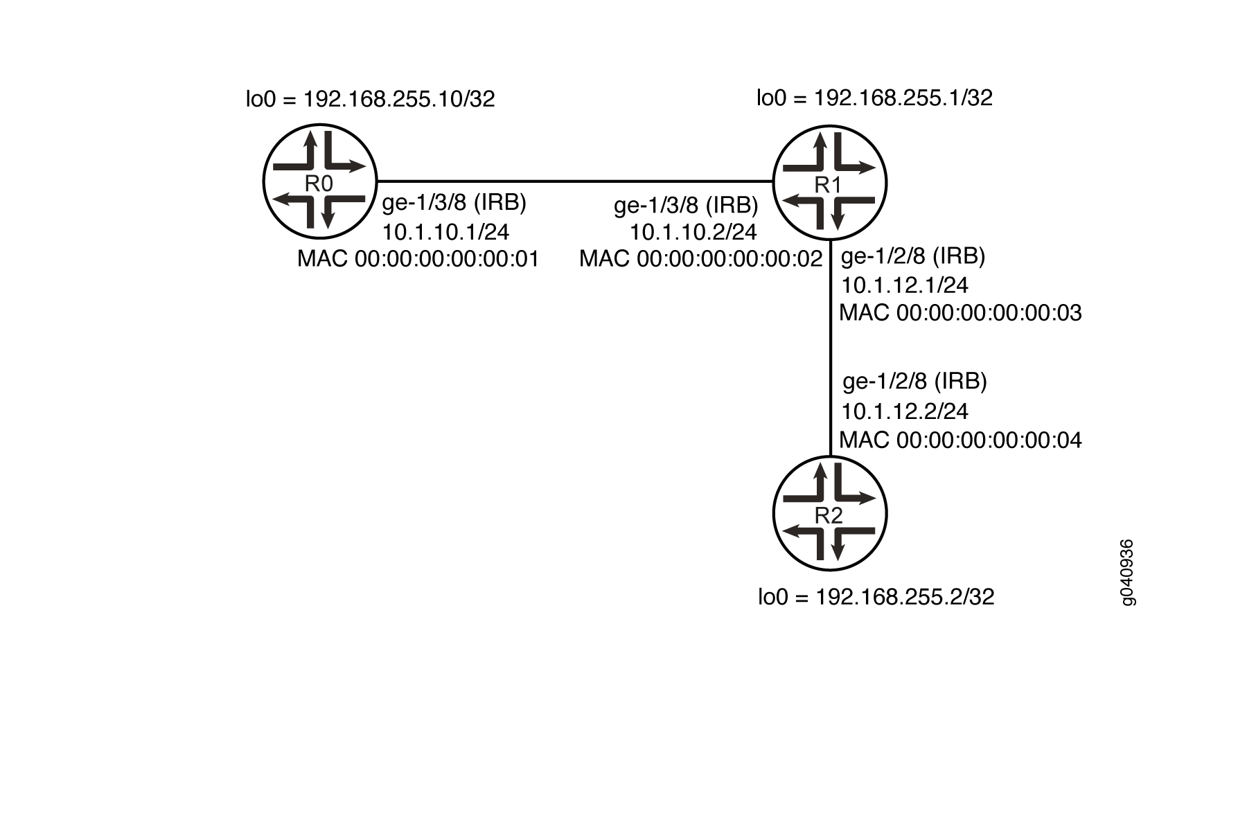
In this example you configure MAC address of IRB logical interfaces.
Configuration
CLI Quick Configuration
To quickly configure this example, copy the following commands, paste them into a
text file, remove any line breaks, change any details necessary to match your
network configuration, and then copy and paste the commands into the CLI at the
[edit] hierarchy level.
Router R0
set interfaces ge-1/3/8 vlan-tagging
set interfaces ge-1/3/8 encapsulation flexible-ethernet-services
set interfaces ge-1/3/8 unit 10 encapsulation vlan-bridge
set interfaces ge-1/3/8 unit 10 vlan-id 10
set interfaces irb unit 10 family inet address 10.1.10.1/24
set interfaces irb unit 10 family mpls
set interfaces irb unit 10 mac 00:00:00:00:00:01
set interfaces lo0 unit 10 family inet address 192.168.255.10/32
set protocols rsvp interface irb.10
set protocols mpls label-switched-path R0-1-R2 to 192.168.255.2
set protocols mpls label-switched-path R0-1-R2 install 192.168.255.2/32 active
set protocols mpls label-switched-path R0-1-R2 no-cspf
set protocols mpls interface irb.10
set protocols bgp group ibgp type internal
set protocols bgp group ibgp local-address 192.168.255.10
set protocols bgp group ibgp neighbor 192.168.255.2
set protocols ospf area 0.0.0.0 interface irb.10
set protocols ospf area 0.0.0.0 interface lo0.10 passive
set protocols ldp interface irb.10
set protocols ldp interface lo0.10
set routing-options autonomous-system 400
set bridge-domains lsbd1 vlan-id 10
set bridge-domains lsbd1 interface ge-1/3/8.10
set bridge-domains lsbd1 routing-interface irb.10
Router R1
set interfaces ge-1/3/8 vlan-tagging
set interfaces ge-1/3/8 encapsulation flexible-ethernet-services
set interfaces ge-1/3/8 unit 10 encapsulation vlan-bridge
set interfaces ge-1/3/8 unit 10 vlan-id 10
set interfaces ge-1/2/8 vlan-tagging
set interfaces ge-1/2/8 encapsulation flexible-ethernet-services
set interfaces ge-1/2/8 unit 40 encapsulation vlan-bridge
set interfaces ge-1/2/8 unit 40 vlan-id 40
set interfaces irb unit 20 family inet address 10.1.10.2/24
set interfaces irb unit 20 family mpls
set interfaces irb unit 20 mac 00:00:00:00:00:02
set interfaces irb unit 30 family inet address 10.1.12.1/24
set interfaces irb unit 30 family mpls
set interfaces irb unit 30 mac 00:00:00:00:00:03
set interfaces lo0 unit 20 family inet address 192.168.255.1/32
set protocols rsvp interface irb.20
set protocols rsvp interface irb.30
set protocols mpls interface irb.30
set protocols mpls interface irb.20
set protocols ospf area 0.0.0.0 interface irb.20
set protocols ospf area 0.0.0.0 interface irb.30
set protocols ospf area 0.0.0.0 interface lo0.20 passive
set protocols ldp interface irb.20
set protocols ldp interface irb.30
set protocols ldp interface lo0.20
set routing-options autonomous-system 400
set bridge-domains lsbd2 vlan-id 10
set bridge-domains lsbd2 interface ge-1/3/8.10
set bridge-domains lsbd2 routing-interface irb.20
set bridge-domains lsbd3 vlan-id 40
set bridge-domains lsbd3 interface ge-1/2/8.40
set bridge-domains lsbd3 routing-interface irb.30
Router R2
set interfaces ge-1/2/8 vlan-tagging
set interfaces ge-1/2/8 encapsulation flexible-ethernet-services
set interfaces ge-1/2/8 unit 40 encapsulation vlan-bridge
set interfaces ge-1/2/8 unit 40 vlan-id 40
set interfaces irb unit 40 family inet address 10.1.12.2/24
set interfaces irb unit 40 family mpls
set interfaces irb unit 40 mac 00:00:00:00:00:04
set interfaces lo0 unit 30 family inet address 192.168.255.2/32
set protocols rsvp interface irb.40
set protocols mpls label-switched-path R2-1-R0 to 192.168.255.10
set protocols mpls label-switched-path R2-1-R0 no-cspf
set protocols mpls interface irb.40
set protocols bgp group ibgp type internal
set protocols bgp group ibgp local-address 192.168.255.2
set protocols bgp group ibgp neighbor 192.168.255.10
set protocols ospf area 0.0.0.0 interface irb.40
set protocols ospf area 0.0.0.0 interface lo0.30 passive
set protocols ldp interface irb.40
set protocols ldp interface lo0.30
set routing-options autonomous-system 400
set bridge-domains lsbd4 vlan-id 40
set bridge-domains lsbd4 interface ge-1/2/8.40
set bridge-domains lsbd4 routing-interface irb.40
Configuring the MAC Address of an IRB Interface
Step-by-Step Procedure
The following example requires that you navigate various levels in the configuration hierarchy. For information about navigating the CLI, see Using the CLI Editor in Configuration Mode in the CLI User Guide.
Repeat this procedure for Juniper Networks Routers R1 and R2, modifying the appropriate interface names, addresses, and any other parameters for each router.
To configure the MAC address of an IRB interface on Router R0:
Configure the physical interfaces.
[edit interfaces ge-1/3/8]user@R0# set vlan-tagging user@R0# set encapsulation flexible-ethernet-services user@R0# set unit 10 encapsulation vlan-bridge user@R0# set unit 10 vlan-id 10Configure the IRB logical interface.
[edit interfaces irb]user@R0# set unit 10 family inet address 10.1.10.1/24 user@R0# set unit 10 family mpls user@R0# set unit 10 mac 00:00:00:00:00:01 [edit interfaces] user@R0# set lo0 unit 10 family inet address 192.168.255.10/32Configure the RSVP protocol.
[edit protocols rsvp]user@R0# set interface irb.10Configure the MPLS protocol.
[edit protocols mpls]user@R0# set label-switched-path R0-1-R2 to 192.168.255.2 user@R0# set label-switched-path R0-1-R2 install 192.168.255.2/32 active user@R0# set label-switched-path R0-1-R2 no-cspf user@R0# set interface irb.10 user@R0# set interface irb.10Configure the BGP protocol.
[edit protocols BGP]user@R0# set group ibgp type internal user@R0# set group ibgp local-address 192.168.255.10 user@R0# set group ibgp neighbor 192.168.255.2Configure the OSPF protocol.
[edit protocols ospf]user@R0# set area 0.0.0.0 interface irb.10 user@R0# set area 0.0.0.0 interface lo0.10 passiveConfigure the LDP protocol.
[edit protocols ldp]user@R0# set interface irb.10 user@R0# set interface lo0.10Configure the autonomous system (AS) number.
[edit routing-options]user@R0# set autonomous-system 400Configure the bridge domains.
[edit]user@R0# set bridge-domains lsbd1 vlan-id 10 user@R0# set bridge-domains lsbd1 interface ge-1/3/8.10 user@R0# set bridge-domains lsbd1 routing-interface irb.10
Results
From configuration mode, enter the show interfaces, show protocols and show bridge-domains, commands and confirm your configuration. If the output does not display the intended configuration, repeat the instructions in this example to correct the configuration.
    user@R0# show interfaces
    ge-1/3/8 {
        unit 10 {
            encapsulation vlan-bridge;
            vlan-id 10;
        }
    }
    irb {
        unit 10 {
            family inet {
                mtu 1450;
                address 10.1.10.1/24;
            }
            family mpls;
            mac 00:00:00:00:00:01;
        }
    }
    lo0 {
        unit 10 {
            family inet {
                address 192.168.255.10/32;
            }
        }
    }
    user@R0# show protocols
    rsvp {
        interface irb.10;
    }
        mpls {
            label-switched-path R0-1-R2 {
                to 192.168.255.2;
                install 192.168.255.2/32 active;
                no-cspf;
            }
            interface irb.10;
        }
        bgp {
            group ibgp {
                type internal;
                local-address 192.168.255.10;
                neighbor 192.168.255.2;
            }
        }
        ospf {
            area 0.0.0.0 {
                interface irb.10;
                interface lo0.10 {
                    passive;
                }
            }
        }
        ldp {
            interface irb.10;
            interface lo0.10;
        }
    user@R0# show bridge-domains
    lsbd1 {
        vlan-id 10;
        interface ge-1/3/8.10;
        routing-interface irb.10;
    }
If you are done configuring the devices, commit the configuration.
user@host# commit
Verification
Confirm that the configuration is working properly.
Verifying the MAC Address of the IRB Interface
Purpose
Verify that the specified MAC address is assigned to the IRB interface.
Action
From operational mode, run the show interfaces irb command
on the device.
user@host# show interfaces irb
Physical interface: irb, Enabled, Physical link is Up
  Interface index: 132, SNMP ifIndex: 505
  Type: Ethernet, Link-level type: Ethernet, MTU: 1514
  Device flags   : Present Running
  Interface flags: SNMP-Traps
  Link type      : Full-Duplex
  Link flags     : None
  Current address: 80:71:1f:c2:58:f0, Hardware address: 80:71:1f:c2:58:f0
  Last flapped   : Never
    Input packets : 0
    Output packets: 0

  Logical interface irb.10 (Index 326) (SNMP ifIndex 634)
    Flags: SNMP-Traps 0x0 Encapsulation: ENET2
    MAC: 00:00:00:00:00:01
    Bandwidth: 1000mbps
    Routing Instance: LS1/default Bridging Domain: lsbd1+10
    Input packets : 55202
    Output packets: 69286
    Protocol inet, MTU: 1450
      Flags: Sendbcast-pkt-to-re, Is-Primary, User-MTU
      Addresses, Flags: Is-Preferred Is-Primary
        Destination: 10.1.10/24, Local: 10.1.10.1, Broadcast: 10.1.10.255
      Addresses, Flags: Is-Preferred
        Destination: 10.1.12/24, Local: 10.1.12.1, Broadcast: 10.1.12.255
    Protocol mpls, MTU: 1500, Maximum labels: 3
      Flags: Is-Primary
    Protocol multiservice, MTU: 1500

  Logical interface irb.20 (Index 358) (SNMP ifIndex 635)
    Flags: SNMP-Traps 0x0 Encapsulation: ENET2
    MAC: 00:00:00:00:00:02
    Bandwidth: 1000mbps
    Routing Instance: LS2/default Bridging Domain: lsbd2+10
    Input packets : 66044
    Output packets: 68464
    Protocol inet, MTU: 1450
      Flags: Sendbcast-pkt-to-re, Is-Primary, User-MTU
      Addresses, Flags: Is-Preferred Is-Primary
        Destination: 10.1.10/24, Local: 10.1.10.2, Broadcast: 10.1.10.255
      Addresses, Flags: Is-Preferred
        Destination: 10.1.12/24, Local: 10.1.12.2, Broadcast: 10.1.12.255
    Protocol mpls, MTU: 1500, Maximum labels: 3
      Flags: Is-Primary
    Protocol multiservice, MTU: 1500

  Logical interface irb.30 (Index 360) (SNMP ifIndex 636)
    Flags: SNMP-Traps 0x0 Encapsulation: ENET2
    MAC: 00:00:00:00:00:03
    Bandwidth: 1000mbps
    Routing Instance: LS2/default Bridging Domain: lsbd3+40
    Input packets : 26948
    Output packets: 53605
    Protocol inet, MTU: 1500
      Flags: Sendbcast-pkt-to-re
      Addresses, Flags: Is-Preferred Is-Primary
        Destination: 10.1.12/24, Local: 10.1.12.2, Broadcast: 10.1.12.255
      Addresses, Flags: Is-Preferred
        Destination: 10.1.10/24, Local: 10.1.10.1, Broadcast: 10.1.10.255
    Protocol mpls, MTU: 1500, Maximum labels: 3
    Protocol multiservice, MTU: 1500

  Logical interface irb.40 (Index 355) (SNMP ifIndex 632)
    Flags: SNMP-Traps 0x0 Encapsulation: ENET2
    MAC: 00:00:00:00:00:04
    Bandwidth: 1000mbps
    Routing Instance: LS3/default Bridging Domain: lsbd4+40
    Input packets : 40575
    Output packets: 31128
    Protocol inet, MTU: 1500
      Flags: Sendbcast-pkt-to-re, Is-Primary
      Addresses, Flags: Is-Preferred Is-Primary
        Destination: 10.1.12/24, Local: 10.1.12.1, Broadcast: 10.1.12.255
    Protocol mpls, MTU: 1500, Maximum labels: 3
      Flags: Is-Primary
    Protocol multiservice, MTU: 1500
Meaning
The output shows the manually configured MAC address in the MAC field.
If you did not configure the MAC address for a logical interface, the output does not include this value. However, the device uses the MAC address of the physical interface during data transmission.