Q-in-Q Support on Redundant Trunk Links Using LAGs with Link Protection
Understanding Q-in-Q Support on RTGs Using LAGs with Link Protection
Redundant trunk links provide a simple solution for network recovery when a trunk port on a switch goes down. In that case, traffic is routed to another trunk port, keeping network convergence time to a minimum.
For information about using redundant trunk links in a legacy redundant trunk groups (RTG) setup—that is, an RTG configuration that does not support Q-in-Q or service-provider configurations—see Understanding Redundant Trunk Links (Legacy RTG Configuration).
You can use this feature of redundant trunk links (or RTG) with Q-in-Q support using LAGs with link protection in both service provider and enterprise configurations.
This feature of RTG with Q-in-Q support includes support for the following items that are not supported in legacy RTG configurations:
Configuration of flexible VLAN tagging on the same LAG that supports the redundant links configurations
Multiple redundant-link configurations on one physical interface
Multicast convergence
The redundant trunk link configuration (also known as a “redundant trunk group (RTG) configuration”) contains two links: a primary or active link and a secondary link. If the primary link fails, the secondary link automatically starts forwarding data traffic without waiting for normal spanning-tree protocol convergence.
Data traffic is forwarded only on the primary link. Data traffic received on the secondary link is dropped.
While data traffic is blocked on the secondary link, Layer 2 control traffic is still permitted. For example, you can run an LLDP session between two switches on the secondary link.
Rapid Spanning Tree Protocol (RSTP) is enabled by default on the switches to create a loop-free topology, but an interface cannot be in both a redundant trunk link and in a spanning-tree protocol topology at the same time. You must disable RSTP on an interface if a redundant trunk link is configured on that interface. Spanning-tree protocols can, however, continue operating on other interfaces on those switches.
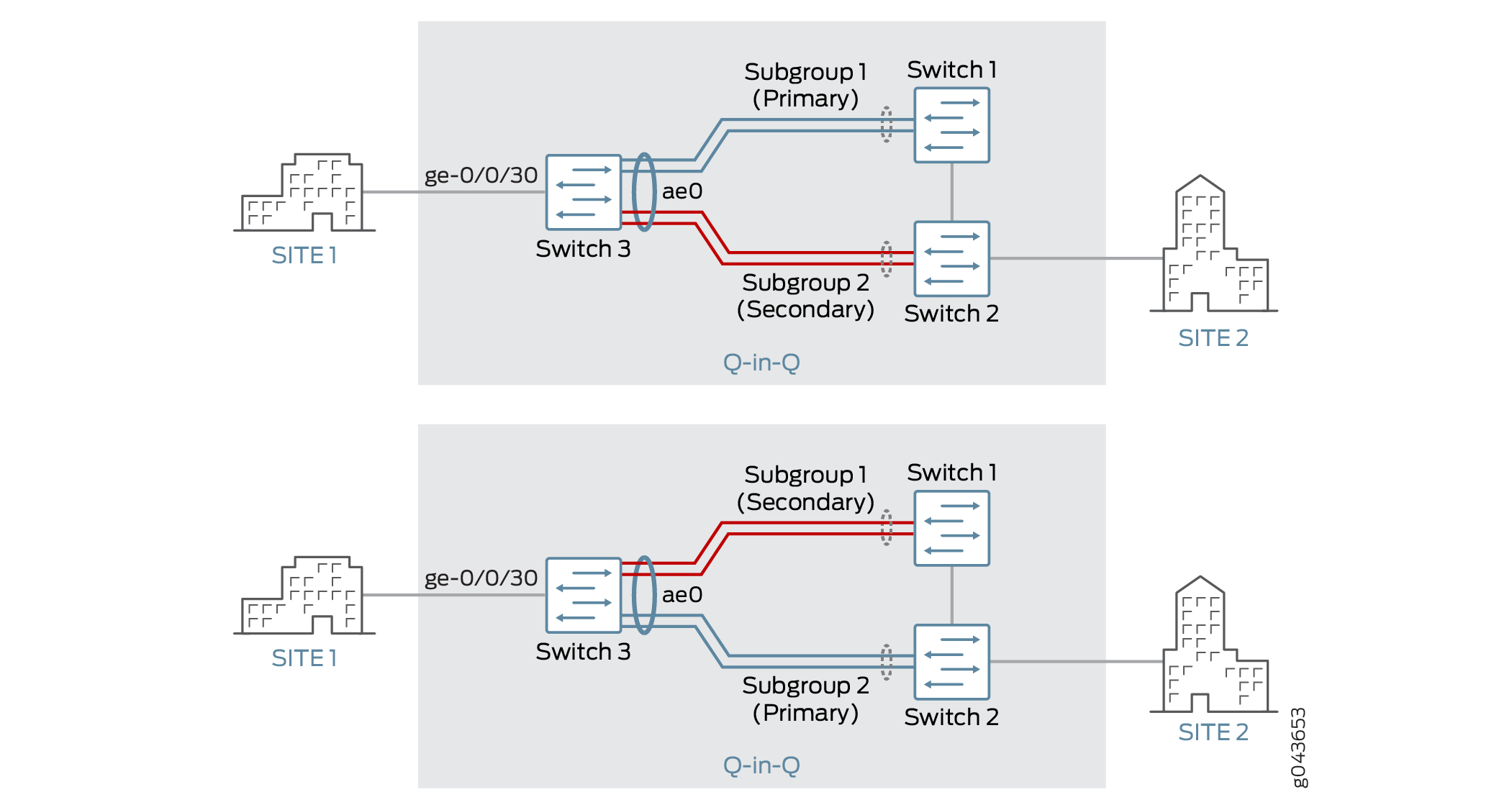
The top of Figure 1 shows three switches in a topology for redundant trunk links on a LAG with flexible VLAN tagging. This particular configuration also includes subgroups that contain multiple links—there can be just two subgroups on the LAG, and both subgroups must have the same number of links.
The topology shown in Figure 1 applies only to the first of the three configurations described later in this topic. See Configuring Redundant Trunk Links on an LACP LAG (N:N Link Protection with Subgroups). While the remaining configuration tasks share some elements of the first task, some absolute values provided in each task are unique to that task—for example, the ingress interface has a different value in each task.
Switch 3 is connected to Switch 1 through Subgroup 1 and to Switch 2 through Subgroup 2. Subgroups 1 and 2 are in an aggregated Ethernet bundle, or link aggregation group (LAG), with interface name ae0. Subgroup 1 is designated as the primary link, and Subgroup 2 is designated as the secondary link. Traffic flows between Switch 3 and Switch 1 through Subgroup 1. While Subgroup 1 is active, Subgroup 2 blocks data traffic.
The bottom of Figure 1 illustrates how the redundant trunk link topology works when the primary link goes down.
When Subgroup 1 between Switch 1 and Switch 3 goes down, Subgroup 2 takes over as the primary (active) link. Traffic flows between Switch 3 and Switch 2 through Subgroup 2.
Here is how multicast convergence works in a topology such as the one illustrated in the preceding figure:
With LAG ae0 being a multicast router port, all IGMP join messages received on Switch 3 are forwarded to Switch 1.
When the link between Switch 3 and Switch 1 goes down, traffic for the multicast source received on Switch 2 is flooded to all ports in the VLAN.
When the primary link goes down, an IGMP general query is sent by Switch 3 to all ports in the VLAN, and the IGMP reports received from clients are forwarded to Switch 2, through which learning happens; thus, multicast convergence is achieved.
Configuring Redundant Trunk Links on a LAG with Link Protection and Flexible VLAN Tagging
There are several variations on the configuration of redundant trunk links on a LAG with link protection and with flexible VLAN tagging.
For illustration purposes only, the following configuration tasks show absolute values, such as ge-0/0/30, rather than variables such as interface-name.
- Configuring Redundant Trunk Links on an LACP LAG (N:N Link Protection with Subgroups)
- Configuring Redundant Trunk Links on a Static LAG (1:1 Link Protection)
- Configuring Redundant Trunk Links on a LAG with Multiple Logical Interfaces (1:1 Link Protection )
- Verifying That Redundant Trunk Links Are Available on the LAG and Viewing Active Links
Configuring Redundant Trunk Links on an LACP LAG (N:N Link Protection with Subgroups)
Configuring Redundant Trunk Links on a Static LAG (1:1 Link Protection)
Configuring Redundant Trunk Links on a LAG with Multiple Logical Interfaces (1:1 Link Protection )
See Also
Verifying That Redundant Trunk Links Are Available on the LAG and Viewing Active Links
Purpose
Verify that the redundant trunk links are available on the LAG, and see which interfaces are configured as the primary (active) links.
Action
Use the following show commands:
show mac-refresh interface-name—Display whether redundant trunk links on a LAG with link protection are enabled on the specified interface.show interfaces ge interface-name extensiveorshow interfaces xe interface-name extensive—On a static LAG, display which interface is set as the primary member.show lacp interfaces—On an LACP LAG, display which member interfaces are active and which are down.