Static VXLAN
Juniper Networks supports the static Virtual Extensible LAN (VXLAN) feature in a small multichassis link aggregation group (MC-LAG) network and in small networks on Layer 2 (L2) VXLAN gateway devices.
Understanding Static VXLAN
Static Virtual Extensible LAN (VXLAN), also known as unicast VXLAN, enables you to statically configure source and destination virtual tunnel endpoints (VTEPs) for a particular traffic flow. A source VTEP encapsulates and a destination VTEP de-encapsulates L2 packets with a VXLAN header, thereby tunneling the packets through an underlying Layer 3 IP network.
Although this feature is also known as unicast VXLAN, static VXLAN tunnels can support both unicast and broadcast, unknown unicast, and multicast (BUM) traffic. We support BUM traffic replication and forwarding using ingress replication.
Starting in Junos OS Release 14.1X53-D40, Juniper Networks supports static VXLAN on devices that act as L2 VXLAN gateway devices. Here we show sample environments with a small MC-LAG network or leaf in a classic spine and leaf fabric.
- Benefits of Static VXLAN
- How Static VXLAN Works
- Small MC-LAG Network Static VXLAN Use Case
- VLAN or Bridge Domain Level Static VXLAN Use Case
Benefits of Static VXLAN
-
Instead of using an Ethernet VPN (EVPN) control plane to learn the MAC addresses of hosts, static VXLAN uses a flooding-and-learning technique in the VXLAN data plane. Therefore, using static VXLAN reduces complexity in the control plane.
-
For a small MC-LAG network, EVPN might be overly complex to configure and maintain. Static VXLAN provides the benefits of VXLAN and is relatively easy to design and configure.
How Static VXLAN Works
To enable static VXLAN on a Juniper Networks device that functions as a VTEP, you must configure:
-
A list that includes one or more remote VTEPs with which the local VTEP can form a VXLAN tunnel.
-
Ingress node replication.
-
The VTEP’s loopback interface (lo0):
-
Configure an anycast IP address as the primary interface.
-
Specify this interface as the source interface for a VXLAN tunnel.
-
When a VTEP receives a BUM packet, the VTEP uses ingress node replication to replicate and flood the packet to the statically defined remote VTEPs on your list. The remote VTEPs in turn flood the packet to the hosts in each VXLAN of which the VTEPs are aware.
The VTEPs learn the MAC addresses of:
-
Remote hosts from the VTEPs on the remote VTEP list.
-
Local hosts from the local access interfaces
Upon learning a MAC address of a host, the device adds the MAC address to the Ethernet switching table.
You can view information about remote static VXLAN VTEP interfaces using the following CLI show commands:
-
show ethernet-switching
                            vxlan-tunnel-end-point-remote
—Shows the remote VTEPs on the device, including their IP addresses and VTEP interface names . See the RVTEP-IP and Interface output fields. -
show interfaces
                            vtep-interface-name
—Displays status of a VTEP interface. The VTEP interfaces you configure as static VXLAN VTEPs display the value Configured-remote in the VXLAN Endpoint type output field of this command.
For example, with static VXLAN remote VTEPs configured for VLANs 200 and 300 in an L2 routing instance named ri1:
user@leaf-1> show ethernet-switching vxlan-tunnel-end-point remote
Logical System Name       Id  SVTEP-IP         IFL   L3-Idx    SVTEP-Mode    ELP-SVTEP-IP
<default>                 0   192.168.1.1      lo0.0    0
RVTEP-IP      IFL-Idx     Interface    NH-Id   RVTEP-Mode  ELP-IP        Flags
192.168.2.1     19307     vtep.32771   53035   RNVE
RVTEP-IP       L2-RTT                  IFL-Idx   Interface     NH-Id  RVTEP-Mode  ELP-IP        Flags
192.168.2.1    ri1                     671522819 vtep-53.32771 53035  RNVE
    VNID          MC-Group-IP
    200           0.0.0.0
    300           0.0.0.0

user@leaf-1> show interfaces vtep.32771
  Logical interface vtep.32771 (Index 20108) (SNMP ifIndex 537)
    Flags: Up Encapsulation: Unspecified
    VXLAN Endpoint Type: Configured-remote, VXLAN Endpoint Address: 192.168.2.1, L3 Routing Instance: default
    Input packets : 0
    Output packets: 0
    Protocol ethernet-switching, MTU: Unlimited
      Flags: None
Small MC-LAG Network Static VXLAN Use Case
Here we show a static VXLAN at the global level in a small network that uses MC-LAGs.
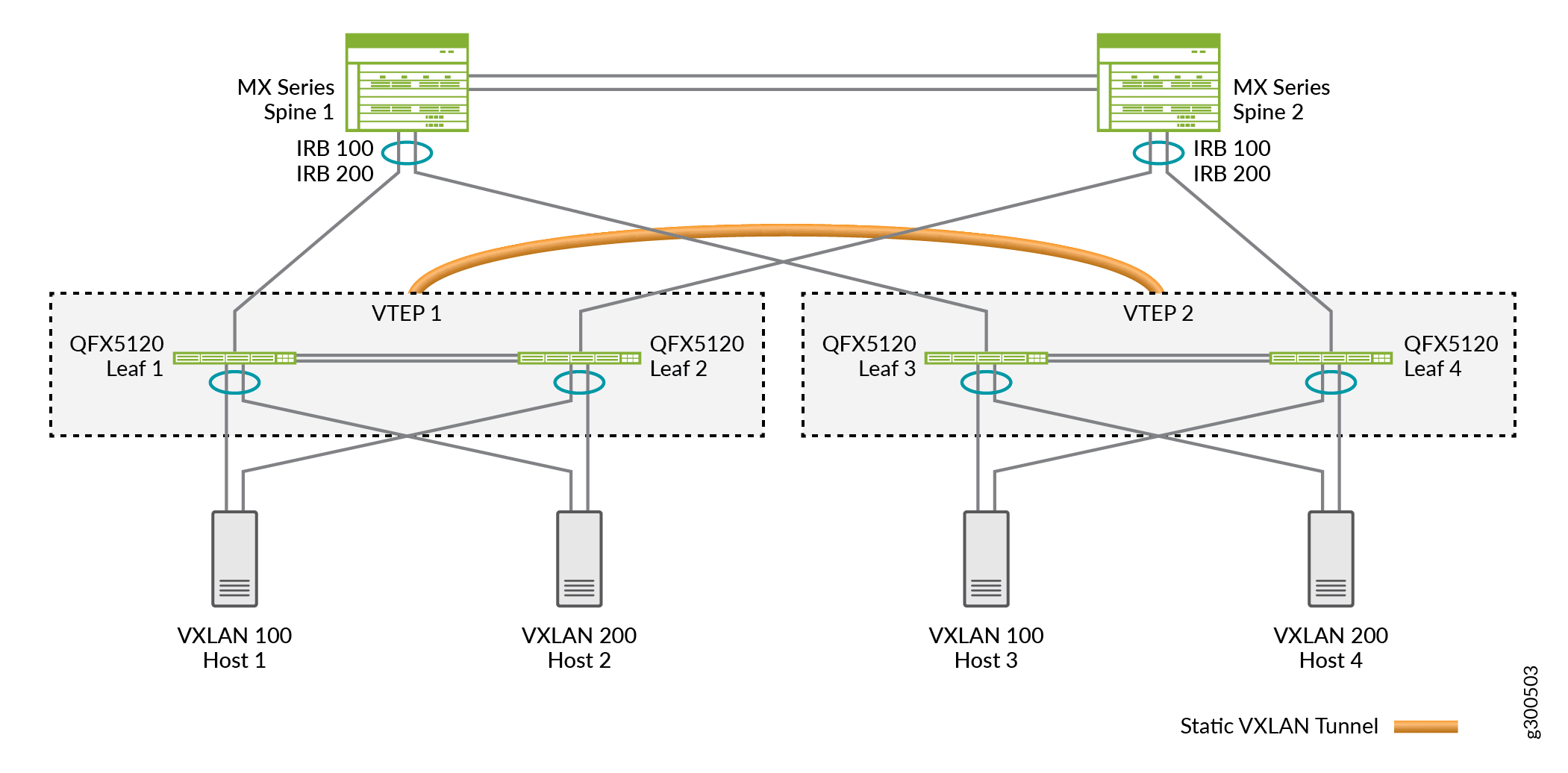
In the MC-LAG network in Figure 1:
-
The bottom layer includes hosts (Host 1 through Host 4), each of which is multihomed to leaf devices and is a member of a VXLAN.
-
The middle layer includes leaf devices (Leaf 1 through Leaf 4), each of which functions as an L2 VXLAN gateway. In addition, Leaf 1 and Leaf 2 form an MC-LAG and together, both leaf devices function as VTEP 1. Leaf 3 and Leaf 4 form another MC-LAG and function as VTEP 2.
-
The top layer includes spine devices (Spine 1 and Spine 2), which form an MC-LAG. These devices function as IP routers.
Note the following about the configuration of Leaf 1 through Leaf 4 on which static VXLAN is configured:
-
Instead of EVPN-VXLAN, here we enable static VXLAN.
-
Each leaf device is an MC-LAG member and functions along with its MC-LAG peer as a VTEP. That is, two physical leaf devices make up each virtual VTEP. This situation impacts the configuration in the following ways:
-
On each leaf device that forms a VTEP, you must configure the same loopback address.
-
On each leaf device that forms a VTEP, you must configure the same remote VTEP list.
For a sample configuration of this use case, see Configure Static VXLAN at the Global Level.
-
-
Instead of an IP multicast feature, we enable ingress node replication.
VLAN or Bridge Domain Level Static VXLAN Use Case
On some platforms, you can set up an L2 VXLAN gateway without EVPN at the VLAN or bridge domain level, In this case, you statically configure a list of one or more remote VTEPs at the global level, and map the list to a particular VLAN or bridge domain.
You don’t configure EVPN as part of a static VXLAN configuration. However, you can have EVPN-VXLAN and static VXLAN configurations on the same device, as long as the two configurations use different sets of remote peer VTEPs.
First, statically configure a global list of remote VTEPs using the
remote-vtep-list [...] statement. Then map the same list of
remote VTEPs at the VLAN or bridge domain level using the
static-remote-vtep-list [...] statement. Each VLAN must
also have a VXLAN network identifier (VNI) mapping.
When you configure static VXLAN in EVPN-VXLAN deployments on the PTX10000
line of routers running Junos OS Evolved, you must also enable the
tunnel-termination option at the [edit
forwarding-options] hierarchy level. This enables the
termination of tunnels on all interfaces at the global level.
We support configuring static VXLAN at the global level, VLAN level, and bridge domain level as follows:
| Static VXLAN Configuration | Supported Platforms |
|---|---|
|
In the default switch instance |
MX Series QFX Series |
|
In a |
MX Series PTX10000 line of routers running Junos OS Evolved |
|
At the global level |
MX Series QFX Series PTX10000 line of routers running Junos OS Evolved |
|
At the VLAN level |
MX Series QFX Series PTX10000 line of routers running Junos OS Evolved |
|
At the bridge domain level |
MX Series |
When you specify the remote VTEPs at the VLAN or bridge domain level:
-
In the default switch instance:
You must also specify the same VTEPs at the global level in the default switch instance at the
[edit switch-options]hierarchy level. -
In a
virtual-switchrouting instance:You must also specify the same VTEPs at the global level in the same routing instance at the
[edit routing-instances
                                    name]
hierarchy level.
To replicate and flood BUM traffic over static VXLAN tunnels at the VLAN or
bridge domain level for VXLANs, you must also configure ingress node replication
mode (ingress-node-replication option) at that level. This mode
restricts the BUM traffic flood domain to only those VTEPs mapped to the
particular VLAN or bridge domain.
For a sample configuration of this use case, see Configure Static VXLAN at the VLAN or Bridge Domain Level on L2 VXLAN Gateway Devices.
Q-in-Q VLAN Tunnels in a Spine-and-Leaf Network with Static VXLAN
Starting in Junos OS Release 23.4R1, Junos OS supports Q-in-Q tunnels in an MC-LAG spine-and-leaf network with static VXLAN tunnels. You must use service provider style configuration to configure Q-in-Q tunnels.
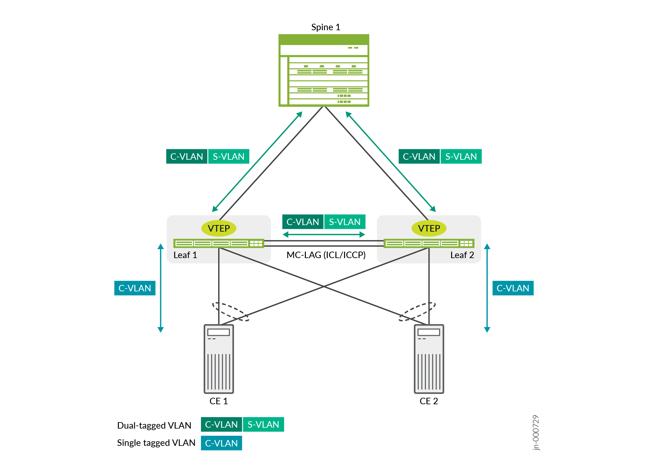
Service providers use Q-in-Q tunnels (VLAN translation) to segregate or bundle customer traffic into fewer or different VLANs by adding another layer of 802.1Q tags. In Q-in-Q tunneling, as a packet travels from a customer VLAN (C-VLAN) to a service provider's VLAN, Junos OS adds a service-provider defined VLAN (S-VLAN) tag to the packet. This additional 802.1Q tag allows service providers to create an L2 Ethernet connection between two customer sites in different geographic locations. As the packets exits the service provider's VLAN, Junos OS removes the extra 802.1Q (S-VLAN) tag.
Figure 2 shows how Junos devices handle Q-in-Q VLAN traffic in a spine-and-leaf topology. Leaf 1 and Leaf 2 are configured as static VXLAN gateway devices. Leaf 1 and Leaf 2 are also configured as MC-LAG peers to provide redundancy and load balancing. The VTEPs on the leaf devices is responsible for pushing the S-VLAN tag to the C-VLAN packet when it sends traffic to the spine and for popping the S-VLAN tag when it receives packets from the spine. In the event of a link failure between a leaf device and CE device, the packet is sent to the other leaf device. In which case, the leaf devices hold onto the S-VLAN tag.
For more information about configuring the different elements in this features, see:
Configure Static VXLAN at the Global Level
You can implement VXLAN using the static VXLAN feature on L2 VXLAN gateway devices. Here we show using a static VXLAN in a small multichassis link aggregation group (MC-LAG) network. In the MC-LAG network, Juniper Networks devices function as source and destination virtual tunnel endpoints (VTEPs). In this environment, static VXLAN serves two purposes:
-
To learn the MAC addresses of hosts in a VXLAN. To accomplish this task, static VXLAN uses the ingress node replication feature to flood BUM packets throughout a VXLAN. The VTEPs learn the MAC addresses of remote hosts from the VTEPs on the remote VTEP list and the MAC addresses of local hosts from the local access interfaces. Upon learning of a host’s MAC address, the MAC address is then added to the Ethernet switching table.
-
To encapsulate L2 packets with a VXLAN header and later de-encapsulate the packets, thereby enabling them to be tunneled through an underlying Layer 3 IP network. For this task to be accomplished, on each VTEP, you configure a list of statically defined remote VTEPs with which the local VTEP can form a VXLAN tunnel.
This sample configuration shows the steps and a sample configuration with the default switch instance rather than an explicitly configured L2 routing instance.
See Configure Static VXLAN at the VLAN or Bridge Domain Level on L2 VXLAN Gateway Devices for a sample
configuration with a different use case—static VXLAN at the VLAN or bridge
domain level. That configuration shows configuration steps and a sample
configuration with an L2 routing instance of type
virtual-switch.
Before You Begin
-
Verify that Ethernet VPN (EVPN) is not enabled on the Juniper Networks devices that function as leaf devices.
-
Verify that IP multicast is not enabled on the leaf devices.
In the sample MC-LAG network shown in Figure 3, note that each VTEP (VTEP 1 and VTEP 2) comprises two physical leaf devices. That is, the two physical leaf devices function as a single virtual entity. As a result, for both leaf devices that compose a VTEP, you must configure the following:
-
The same loopback anycast IP address.
-
The same remote VTEP list.
Table 2 shows the sample loopback address and remote VTEP list configured on each leaf device in the network.
|
Static VXLAN Parameters |
VTEP 1: Leaf 1 Configuration |
VTEP 1: Leaf 2 Configuration |
VTEP 2: Leaf 3 Configuration |
VTEP 2: Leaf 4 Configuration |
|---|---|---|---|---|
|
Loopback anycast IP address |
192.168.99.110/32 |
192.168.99.110/32 |
192.168.99.120/32 |
192.168.99.120/32 |
|
Remote VTEP list |
192.168.99.120 |
192.168.99.120 |
192.168.99.110 |
192.168.99.110 |
This procedure focuses on configuring the static VXLAN feature. It does not show how to configure peripheral but related entities such as interfaces, VLANs, and so on. However, the sample configuration that follows the procedure includes a more comprehensive configuration, including the related entities.
To enable static VXLAN on a leaf device:
Sample Static VXLAN Configuration
These show configuration output snippets display a static VXLAN
sample configuration for leafs 1 and 2 (VTEP 1) and include the parameters
outlined in Table 2.
interfaces {
. . .
    ae0 {
        unit 0 {
            family ethernet-switching {
                interface-mode trunk;
                vlan {
                    members 100 200;
                }
            }
        }
    }
. . .
    lo0 {
        unit 0 {
            family inet {
                address 192.168.99.110/32 {
                    primary;
                }
            }
        }
    }
}
. . .
switch-options {
       vtep-source-interface lo0.0;
       remote-vtep-list 192.168.99.120;
}
. . .
vlans {
    vlan100 {
        vlan-id 100;
        vxlan {
            vni 1100;
            ingress-node-replication;
        }
    }
    vlan200 {
        vlan-id 200;
        vxlan {
            vni 2200;
            ingress-node-replication;
        }
    }
}
Configure Static VXLAN at the VLAN or Bridge Domain Level on L2 VXLAN Gateway Devices
In small spine and leaf networks, you can enable the static VXLAN feature on L2 VXLAN gateway devices that function as source and destination virtual tunnel endpoints (VTEPs). The L2 VXLAN gateway devices tunnel L2 packets over a VXLAN tunnel through an underlying Layer 3 IP network by:
-
Encapsulating L2 packets with a VXLAN header when sending the packets to remote VTEPs.
-
De-encapsulating the packets when receiving them from the tunnel to send to the destination hosts.
In this case, for each VTEP on the L2 VXLAN gateway devices, at the global level, statically configure the list of remote VTEPs with which the local VTEP can form a VXLAN tunnel. Then map the VTEP list to a particular VLAN or bridge domain in an L2 routing instance.
-
Statically configure a global list of remote VTEPs using the
remote-vtep-liststatement as follows:In the default switch instance:
set switch-options remote-vtep-list [vtep-ip-addr1 <vtep-ip-addr2 ...>]
In a
virtual-switchrouting instance:set <routing-instances name> remote-vtep-list [vtep-ip-addr1 <vtep-ip-addr2 ...>]
-
Map the remote VTEPs list to a particular VLAN or bridge domain as follows:
-
Configure the VLAN with a VXLAN VNI mapping
-
Map the remote VTEPs list to the VLAN using the
static-remote-vtep-liststatement:In the default switch instance:
set vlans vlan-name vxlan static-remote-vtep-list [vtep-ip-addr1 <vtep-ip-addr2 ...>]
In a
virtual-switchrouting instance:set <routing-instances name> vlans vlan-name vxlan static-remote-vtep-list [vtep-ip-addr1 <vtep-ip-addr2 ...>]
-
See VLAN or Bridge Domain Level Static VXLAN Use Case for an overview of how static VXLAN works in this case. See Table 1 for a summary of the supported static VXLAN configurations.
If you configure a global list of remote VTEPs in a routing instance using the
remote-vtep-list statement, but you don't also configure
the static-remote-vtep-list statement for a VLAN in the routing
instance, then that VLAN inherits all the globally configured remote VTEPs.
Here we include the configuration steps and a simple sample configuration on two
L2 VXLAN gateway devices to set up static VXLAN tunnels between them at the VLAN
level. Table 3 shows the parameters for this configuration. We use L2
routing instances of type virtual-switch, so you configure most
elements in the routing instance at the [edit routing-instances
name] hierarchy level. Each step notes the
statement hierarchy differences for the default switch instance instead.
| Device | lo0 IP Address | L2 Instance Name | Associated VLAN | VLAN to VNI mapping | Remote VTEP IP Addresses |
|---|---|---|---|---|---|
| VXLAN-GW1 | 192.168.4.1 | rt1 | v100 (VLAN ID 100) | 100 | 192.168.5.1 |
| v200 (VLAN ID 200) | 200 | ||||
| VXLAN-GW2 | 192.168.5.1 | rt1 | v100 (VLAN ID 100) | 100 | 192.168.4.1 |
| v200 (VLAN ID 200) | 200 |
See the following sample set command configuration blocks that show complementary configurations on VXLAN-GW1 and VXLAN-GW2. Using the parameters in Table 3, these commands set up a static VXLAN tunnel between the two devices in L2 routing instance rt1 at the VLAN level for VLANs 100 and 200.
VXLAN-GW1:
set interfaces et-0/0/3 unit 0 family inet address 10.1.1.1/24
set interfaces et-0/0/7 unit 0 family ethernet-switching interface-mode trunk
set interfaces et-0/0/7 unit 0 family ethernet-switching vlan members 100
set interfaces et-0/0/7 unit 0 family ethernet-switching vlan members 200
set interfaces lo0 unit 0 family inet address 192.168.4.1/32 primary
set interfaces lo0 unit 0 family inet address 192.168.4.1/32 preferred
set routing-instances rt1 instance-type virtual-switch
set routing-instances rt1 vtep-source-interface lo0.0
set routing-instances rt1 remote-vtep-list 192.168.5.1
set routing-instances rt1 interface et-0/0/7.0
set routing-instances rt1 vlans v100 vlan-id 100
set routing-instances rt1 vlans v100 vxlan vni 100
set routing-instances rt1 vlans v100 vxlan ingress-node-replication
set routing-instances rt1 vlans v100 vxlan static-remote-vtep-list 192.168.5.1
set routing-instances rt1 vlans v200 vlan-id 200
set routing-instances rt1 vlans v200 vxlan vni 200
set routing-instances rt1 vlans v200 vxlan ingress-node-replication
set routing-instances rt1 vlans v200 vxlan static-remote-vtep-list 192.168.5.1
set protocols ospf area 0.0.0.0 interface lo0.0 passive
set protocols ospf area 0.0.0.0 interface et-0/0/3.0
VXLAN-GW2:
set interfaces ge-0/0/1 unit 0 family inet address 10.1.1.2/24
set interfaces ge-0/0/3 unit 0 family ethernet-switching interface-mode trunk
set interfaces ge-0/0/3 unit 0 family ethernet-switching vlan members 100
set interfaces ge-0/0/3 unit 0 family ethernet-switching vlan members 200
set interfaces lo0 unit 0 family inet address 192.168.5.1/32 primary
set interfaces lo0 unit 0 family inet address 192.168.5.1/32 preferred
set routing-instances rt1 instance-type virtual-switch
set routing-instances rt1 vtep-source-interface lo0.0
set routing-instances rt1 remote-vtep-list 192.168.4.1
set routing-instances rt1 interface ge-0/0/3.0
set routing-instances rt1 vlans v100 vlan-id 100
set routing-instances rt1 vlans v100 vxlan vni 100
set routing-instances rt1 vlans v100 vxlan ingress-node-replication
set routing-instances rt1 vlans v100 vxlan static-remote-vtep-list 192.168.4.1
set routing-instances rt1 vlans v200 vlan-id 200
set routing-instances rt1 vlans v200 vxlan vni 200
set routing-instances rt1 vlans v200 vxlan ingress-node-replication
set routing-instances rt1 vlans v200 vxlan static-remote-vtep-list 192.168.4.1
set protocols ospf area 0.0.0.0 interface lo0.0 passive
set protocols ospf area 0.0.0.0 interface ge-0/0/1.0
Change History Table
Feature support is determined by the platform and release you are using. Use Feature Explorer to determine if a feature is supported on your platform.