Maintain MX304 Cooling System Components
Maintain the MX304 Air Filter
Purpose
For optimum cooling, verify the condition of the air filter.
Action
Regularly inspect the air filter. A dirty air filter restricts airflow in the unit which negatively affects the router ventilation, The filter degrades over time. You must replace it every 6 months.
CAUTION:Always keep the air filter in place while the device is operating, except during replacement. The fans are very powerful and can pull small bits of wire or other materials into the device if the air filter isn't in place. These materials can damage device components.
The shelf life of polyurethane filter varies from two years to five years depending on the storage conditions. Store in a cool, dry, and dark environment. Wrap the media in plastic and store in an environment with relative humidity between 40%- 80% and temperature between 40°F (4°C) to 90°F (32° C). Note that if the material flakes, or becomes brittle when rubbed or deformed, it is no longer usable.
Replace the MX304 Air Filter Unit
The air filter unit has three parts. The air filter sits right inside the outer filter cover and the inner cage. The air filter unit is installed into the cable management brackets, and is held tightly by captive screws.
Remove the MX304 Air Filter Unit
The air filter unit is designed to prevent dust from being drawn into the chassis.
To remove the air filter unit from the front of the router:
-
Grasp the air filter unit and gently pull it out of the cable management brackets.
See Figure 1.
Figure 1: Remove the Air Filter from the Chassis

Install the MX304 Air Filter Unit
The air filter unit is installed on the cable management brackets. Before installing the air filter unit, ensure that the cable management brackets are already installed on the front of the router.
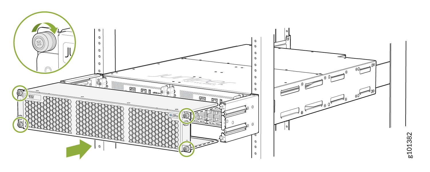
To install the air filter unit:
-
With the air filter unit right side up, slide it into the rails on the cable
management brackets until it stops (see Figure 2). The air filter
unit fits snugly on the cable management brackets.
Figure 2: Install the Air Filter
Replace the MX304 Air Filter
The air filter unit has three parts. The air filter sits right inside the outer filter cover and the inner cage. The air filter unit is installed into the cable management brackets, and is held tightly by captive screws.
Regularly inspect the air filter. A dirty air filter restricts airflow in the unit, producing a negative effect on the ventilation of the chassis.
Remove the MX304 Air Filter
Always keep the air filter unit in place while the router is operating, except during replacement. Because the fans are very powerful, they could pull small bits of wire or other materials into the router through the unfiltered air intake. This could damage the router components.
To remove the air filter:
-
Pull the air filter straight out from the air filter unit.
Figure 3: Remove the Air Filter from the Air Filter Unit
 1—Outer filter cover3—Inner filter cage2—Air filter
Install the MX304 Air Filter
The air filter unit is installed on the cable management brackets. Before installing the air filter unit, ensure that the cable management brackets are already installed on the front of the router.
To install the air filter:
-
Slide the air filter straight onto inner filter cage.
Figure 4: Install the Air Filter from the Air Filter Unit
1—Outer filter cover3—Inner filter cage2—Air filter
Maintain the MX304 Fan Module
Purpose
For optimum cooling, verify the condition of the fans.
Action
Monitor the status of the fans. A fan module contains multiple fans that work in unison to cool the router components. If one fan fails, the router adjusts the speed of the remaining fans to maintain proper cooling. A red alarm is triggered when a fan fails, and when a fan module is removed.
To display the status of the cooling system, issue the
show chassis environmentcommand. The output is similar to the following:user@host> show chassis environment Class Item Status Measurement Routing Engine 0 CPU OK 38 degrees C / 100 degrees F RE 0 CPU Core-0 Temp OK 38 degrees C / 100 degrees F RE 0 CPU Core-1 Temp OK 37 degrees C / 98 degrees F RE 0 CPU Core-2 Temp OK 36 degrees C / 96 degrees F RE 0 CPU Core-3 Temp OK 36 degrees C / 96 degrees F RE 0 CPU Core-4 Temp OK 34 degrees C / 93 degrees F RE 0 CPU Core-5 Temp OK 38 degrees C / 100 degrees F RE 0 CPU Core-6 Temp OK 34 degrees C / 93 degrees F RE 0 CPU Core-7 Temp OK 37 degrees C / 98 degrees F RE 0 Exhaust_right OK 34 degrees C / 93 degrees F RE 0 Inlet_Left OK 26 degrees C / 78 degrees F RE 0 Exhaust_Left OK 32 degrees C / 89 degrees F RE 0 Inlet_right OK 29 degrees C / 84 degrees F Temp CB 0 Exhaust_A OK 41 degrees C / 105 degrees F CB 0 Exhaust_B OK 40 degrees C / 104 degrees F CB 0 Exhaust_C OK 37 degrees C / 98 degrees F CB 0 Intake_A OK 45 degrees C / 113 degrees F CB 0 Intake_B OK 35 degrees C / 95 degrees F CB 0 Onboard OK 37 degrees C / 98 degrees F CB 0 PEX Die OK 29 degrees C / 84 degrees F FPC 0 PMB_CPU OK 28 degrees C / 82 degrees F FPC 0 PMB_DIMM-0 OK 36 degrees C / 96 degrees F FPC 0 PMB_DIMM-1 OK 41 degrees C / 105 degrees F FPC 0 YT0-therm_sensor OK 60 degrees C / 140 degrees F FPC 0 YT1-therm_sensor OK 66 degrees C / 150 degrees F FPC 0 YT2-therm_sensor OK 70 degrees C / 158 degrees F FPC 0 YT0-test_macro OK 61 degrees C / 141 degrees F FPC 0 YT1-test_macro OK 67 degrees C / 152 degrees F FPC 0 YT2-test_macro OK 71 degrees C / 159 degrees F FPC 0 YT0-pgio_slice0 OK 65 degrees C / 149 degrees F FPC 0 YT1-pgio_slice0 OK 77 degrees C / 170 degrees F FPC 0 YT2-pgio_slice0 OK 74 degrees C / 165 degrees F FPC 0 YT0-core_pll OK 60 degrees C / 140 degrees F FPC 0 YT1-core_pll OK 66 degrees C / 150 degrees F FPC 0 YT2-core_pll OK 70 degrees C / 158 degrees F FPC 0 YT0-fabio_slice0 OK 63 degrees C / 145 degrees F FPC 0 YT1-fabio_slice0 OK 64 degrees C / 147 degrees F FPC 0 YT2-fabio_slice0 OK 71 degrees C / 159 degrees F FPC 0 YT0-pgio_slice1 OK 66 degrees C / 150 degrees F FPC 0 YT1-pgio_slice1 OK 70 degrees C / 158 degrees F FPC 0 YT2-pgio_slice1 OK 76 degrees C / 168 degrees F FPC 0 YT0-fabio_slice1 OK 63 degrees C / 145 degrees F FPC 0 YT1-fabio_slice1 OK 63 degrees C / 145 degrees F FPC 0 YT2-fabio_slice1 OK 72 degrees C / 161 degrees F FPC 0 YT0-hbmio_slice1 OK 61 degrees C / 141 degrees F FPC 0 YT1-hbmio_slice1 OK 62 degrees C / 143 degrees F FPC 0 YT2-hbmio_slice1 OK 70 degrees C / 158 degrees F FPC 0 YT0-wanio_misc OK 62 degrees C / 143 degrees F FPC 0 YT1-wanio_misc OK 66 degrees C / 150 degrees F FPC 0 YT2-wanio_misc OK 71 degrees C / 159 degrees F FPC 0 YT0-HBM0 OK 55 degrees C / 131 degrees F FPC 0 YT1-HBM0 OK 56 degrees C / 132 degrees F FPC 0 YT2-HBM0 OK 60 degrees C / 140 degrees F FPC 0 YT0-HBM1 OK 56 degrees C / 132 degrees F FPC 0 YT1-HBM1 OK 56 degrees C / 132 degrees F FPC 0 YT2-HBM1 OK 62 degrees C / 143 degrees F FPC 0 WAN RT0.0 OK 85 degrees C / 185 degrees F FPC 0 WAN RT1.0 OK 89 degrees C / 192 degrees F FPC 0 WAN RT2.0 OK 85 degrees C / 185 degrees F FPC 0 WAN RT3.0 OK 87 degrees C / 188 degrees F FPC 0 WAN RT4.0 OK 85 degrees C / 185 degrees F FPC 0 WAN RT5.0 OK 86 degrees C / 186 degrees F FPC 0 WAN RT6.0 OK 88 degrees C / 190 degrees F FPC 0 WAN RT7.0 OK 90 degrees C / 194 degrees F FPC 0 WAN RT8.0 OK 87 degrees C / 188 degrees F FPC 0 WAN RT9.0 OK 91 degrees C / 195 degrees F FPC 0 WAN RT10.0 OK 86 degrees C / 186 degrees F FPC 0 WAN RT11.0 OK 87 degrees C / 188 degrees F FPC 0 WAN RT12.0 OK 95 degrees C / 203 degrees F FPC 0 WAN RT13.0 OK 95 degrees C / 203 degrees F FPC 0 WAN RT14.0 OK 93 degrees C / 199 degrees F FPC 0 WAN RT15.0 OK 96 degrees C / 204 degrees F FPC 0 WAN RT16.0 OK 96 degrees C / 204 degrees F FPC 0 WAN RT17.0 OK 94 degrees C / 201 degrees F FPC 0 PIC0-Intake-A Temp Sensor OK 50 degrees C / 122 degrees F FPC 0 PIC0-Intake-B Temp Sensor OK 51 degrees C / 123 degrees F FPC 0 PIC0-Exhaust Temp Sensor OK 44 degrees C / 111 degrees F FPC 0 PIC0-YT Junction Temp Sensor OK 66 degrees C / 150 degrees F FPC 0 PIC0-MAX20754_YT_VDD0V75_T OK 57 degrees C / 134 degrees F FPC 0 PIC0-MAX20743_YT_HBM_VDDQ1V2_T OK 57 degrees C / 134 degrees F FPC 0 PIC0-MAX20743_YT_HBM_VDDC1V2_T OK 58 degrees C / 136 degrees F FPC 0 PIC0-MAX20743_YT_RTVDD0V75_T OK 63 degrees C / 145 degrees F FPC 0 PIC0-MAX20796_WAN_VDD0V8_A_T OK 101 degrees C / 213 degrees F FPC 0 PIC0-MAX20743_WAN_VDD3V3_A_T OK 71 degrees C / 159 degrees F FPC 0 PIC0-MAX20743_WAN_AVDD1V2_A_T OK 70 degrees C / 158 degrees F FPC 0 PIC0-MAX20796_WAN_VDD0V8_B_T OK 73 degrees C / 163 degrees F FPC 0 PIC0-MAX20743_WAN_VDD3V3_B_T OK 101 degrees C / 213 degrees F FPC 0 PIC0-MAX20743_WAN_AVDD1V2_B_T OK 73 degrees C / 163 degrees F FPC 0 PIC0-MAX16545_VDD12V0_T Absent 46 degrees C / 114 degrees F FPC 0 PIC1-Intake-A Temp Sensor OK 49 degrees C / 120 degrees F FPC 0 PIC1-Intake-B Temp Sensor OK 48 degrees C / 118 degrees F FPC 0 PIC1-Exhaust Temp Sensor OK 39 degrees C / 102 degrees F FPC 0 PIC1-YT Junction Temp Sensor OK 69 degrees C / 156 degrees F FPC 0 PIC1-MAX20754_YT_VDD0V75_T OK 57 degrees C / 134 degrees F FPC 0 PIC1-MAX20743_YT_HBM_VDDQ1V2_T OK 54 degrees C / 129 degrees F FPC 0 PIC1-MAX20743_YT_HBM_VDDC1V2_T OK 53 degrees C / 127 degrees F FPC 0 PIC1-MAX20743_YT_RTVDD0V75_T OK 59 degrees C / 138 degrees F FPC 0 PIC1-MAX20796_WAN_VDD0V8_A_T OK 94 degrees C / 201 degrees F FPC 0 PIC1-MAX20743_WAN_VDD3V3_A_T OK 65 degrees C / 149 degrees F FPC 0 PIC1-MAX20743_WAN_AVDD1V2_A_T OK 70 degrees C / 158 degrees F FPC 0 PIC1-MAX20796_WAN_VDD0V8_B_T OK 68 degrees C / 154 degrees F FPC 0 PIC1-MAX20743_WAN_VDD3V3_B_T OK 100 degrees C / 212 degrees F FPC 0 PIC1-MAX20743_WAN_AVDD1V2_B_T OK 76 degrees C / 168 degrees F FPC 0 PIC1-MAX16545_VDD12V0_T OK 46 degrees C / 114 degrees F FPC 0 PIC2-Intake-A Temp Sensor OK 54 degrees C / 129 degrees F FPC 0 PIC2-Intake-B Temp Sensor OK 50 degrees C / 122 degrees F FPC 0 PIC2-Exhaust Temp Sensor OK 39 degrees C / 102 degrees F FPC 0 PIC2-YT Junction Temp Sensor OK 71 degrees C / 159 degrees F FPC 0 PIC2-MAX20754_YT_VDD0V75_T OK 60 degrees C / 140 degrees F FPC 0 PIC2-MAX20743_YT_HBM_VDDQ1V2_T OK 63 degrees C / 145 degrees F FPC 0 PIC2-MAX20743_YT_HBM_VDDC1V2_T OK 65 degrees C / 149 degrees F FPC 0 PIC2-MAX20743_YT_RTVDD0V75_T OK 65 degrees C / 149 degrees F FPC 0 PIC2-MAX20796_WAN_VDD0V8_A_T OK 108 degrees C / 226 degrees F FPC 0 PIC2-MAX20743_WAN_VDD3V3_A_T OK 83 degrees C / 181 degrees F FPC 0 PIC2-MAX20743_WAN_AVDD1V2_A_T OK 76 degrees C / 168 degrees F FPC 0 PIC2-MAX20796_WAN_VDD0V8_B_T OK 69 degrees C / 156 degrees F FPC 0 PIC2-MAX20743_WAN_VDD3V3_B_T OK 103 degrees C / 217 degrees F FPC 0 PIC2-MAX20743_WAN_AVDD1V2_B_T OK 79 degrees C / 174 degrees F FPC 0 PIC2-MAX16545_VDD12V0_T OK 51 degrees C / 123 degrees F SFB Exhaust_A OK 44 degrees C / 111 degrees F SFB Exhaust_B OK 44 degrees C / 111 degrees F SFB Intake_A OK 33 degrees C / 91 degrees F SFB Intake_B OK 42 degrees C / 107 degrees F SFB Middle Inlet OK 41 degrees C / 105 degrees F SFB ZF Temp OK 59 degrees C / 138 degrees F Power PEM 0 OK 28 degrees C / 82 degrees F PEM 1 Absent Fans Fan Tray 0 Fan 0 OK Spinning at normal speed Fan Tray 0 Fan 1 OK Spinning at normal speed Fan Tray 1 Fan 0 OK Spinning at normal speed Fan Tray 1 Fan 1 OK Spinning at normal speed Fan Tray 2 Fan 0 OK Spinning at normal speed Fan Tray 2 Fan 1 OK Spinning at normal speed
Replace an MX304 Fan Module
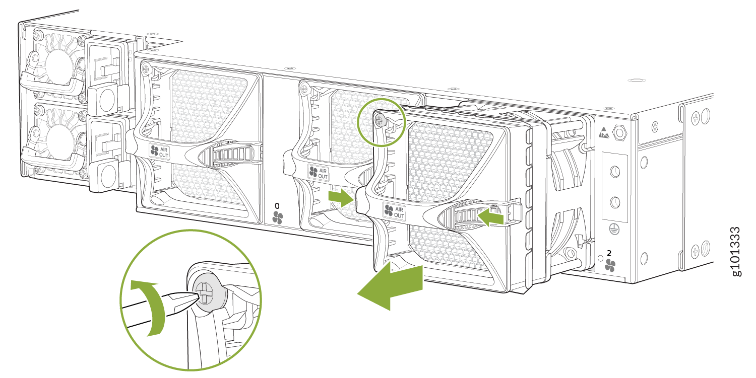
Remove an MX304 Fan Module
To prevent overheating, install the replacement fan module immediately after removing the existing fan module.
To remove the fan module (see Figure 5):
Install an MX304 Fan Module
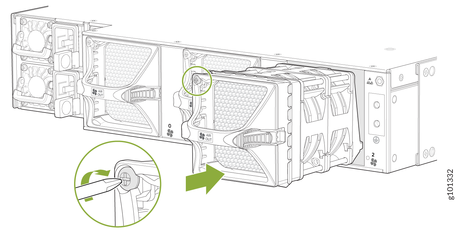
To install the fan module (see Figure 6):
- Attach an ESD grounding strap to your bare wrist and connect the strap to one of the ESD points on the chassis.
- Grasp the fan module by the handle, and place one hand under the fan module for support.
- Place the fan module on the respective slot, and carefully push the fan module into the chassis until the socket lock snaps into place and holds it.
- Using a number-2 Phillips screwdriver, turn the locking screw on the fan module faceplate until it is tight and secured.