Maintain MX304 Power System Components
Maintain the Power Supplies
Purpose
For optimum router performance, verify the condition of the power supplies.
Action
On a regular basis check the power supply status:
Issue the
show chassis powerCLI command. The output is similar to the following:user@host> show chassis power PEM 0: State: Empty Input: Absent PEM 1: State: Online Capacity: 2200 W (maximum 2200 W) DC output: 972 W (zone 0, 81 A at 12 V, 44% of capacity) System: Zone 0: Capacity: 2200 W (maximum 2200 W) Allocated power: 1740 W (460 W remaining) Actual usage: 972 W Total system capacity: 2200 W (maximum 2200 W) Total remaining power: 460 W ...Arrange the power and grounding cables in a way so that they do not obstruct access to other router components.
Routinely check the status LEDs on the power supply faceplates and the craft interface to determine if the power supplies are functioning normally.
Check the red and yellow alarm LEDs on the RE interface. If a power supply fails or you remove a power supply, it triggers an alarm that causes one or both LEDs to light. To find out the associated error messages, issue the following command:
user@host> show chassis alarms
Periodically inspect the site to ensure that the grounding and power cables connected to the router are securely in place and that there's no moisture accumulating near the router.
Do not mix AC and DC power supplies in the same chassis.
Replace an MX304 AC Power Supply
Remove an MX304 AC Power Supply
Before you remove a power supply, be aware of the following:
To maintain proper cooling and prevent thermal shutdown of the operating power supply unit, each power supply slot must contain a power supply. If you remove a power supply, you must install a replacement power supply shortly after the removal.
The minimum required number of power supplies must be present in the router at all times.
After powering off a power supply, wait at least 60 seconds before turning it back on.
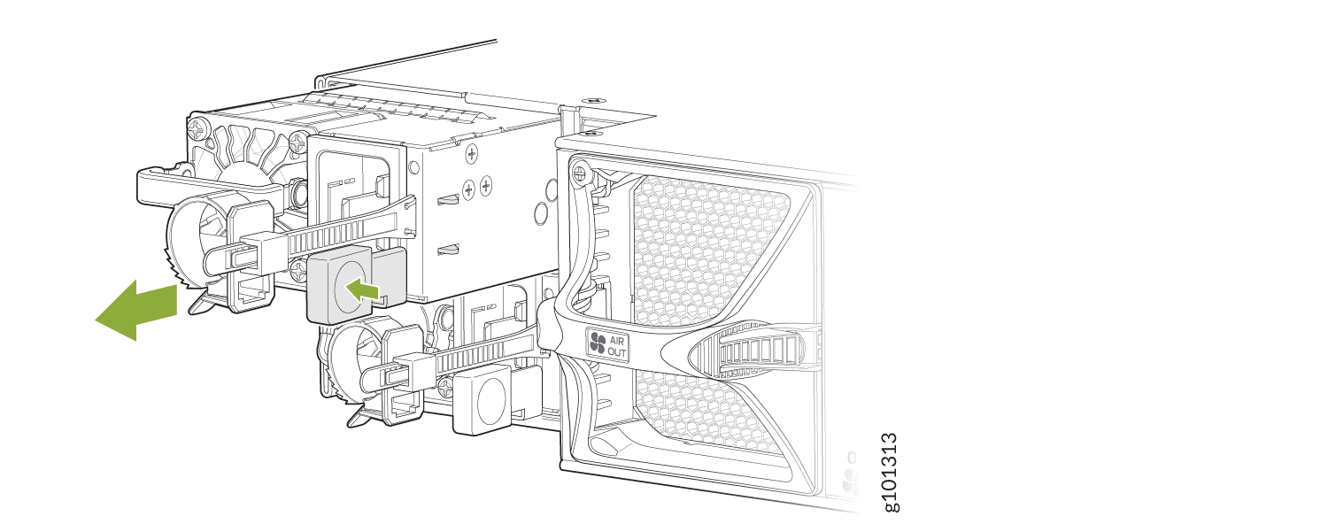
To remove an AC power supply (see Figure 1):
- Switch off the dedicated customer-site circuit breaker for the power supply, and remove the power cord from the AC power source. Follow the instructions for your site.
- Attach an ESD grounding strap to your bare wrist and connect the strap to one of the ESD points on the chassis.
- Press the release latch on the right side of the AC power supply to disconnect the power supply from the chassis (see Figure 1).
- Pull the power supply straight out of the chassis.
Install an MX304 AC Power Supply
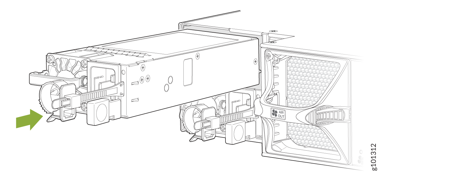
To install an AC power supply (see Figure 2):
- Attach an ESD grounding strap to your bare wrist and connect the strap to one of the ESD points on the chassis.
- Using both hands, hold and slide the AC power supply straight into the chassis until the power supply is fully seated in the chassis slot. The power supply faceplate must be aligned with any adjacent power supply faceplate installed in the power supply slot.
- Press the latch located on the left side of the power supply to slide it into the chassis.
- Attach the power cord to the power supply.
- Push the retainer clip through the loop and tighten it until it fits snug around the power cord.
- Attach the power cord to the AC power source, and switch on the dedicated customer-site circuit breaker. Follow the instructions for your site.
- Observe the status LED on the power supply faceplate. If the power supply is correctly installed and functioning normally, the status LED lights green steadily.
Replace an MX304 DC Power Supply
Remove an MX304 DC Power Supply
Before you remove a power supply, be aware of the following:
The minimum required number of power supplies must be present in the router at all times.
Before you perform DC power procedures, ensure there is no power to the DC circuit. To ensure that all power is off, locate the circuit breaker on the panel board that services the DC circuit, switch the circuit breaker to the off position, and tape the switch handle of the circuit breaker in the off position.
To maintain proper cooling and prevent thermal shutdown of the operating power supply unit, each power supply slot must contain a power supply. If you remove a power supply, you must install a replacement power supply shortly after the removal.
After powering off a power supply, wait at least 60 seconds before turning it back on.
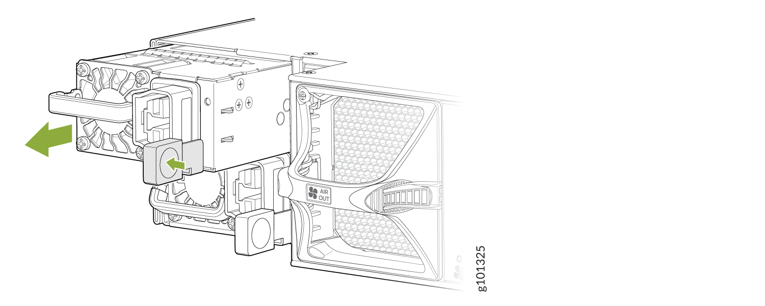
To remove a DC power supply:
-
Pull the power supply straight out of the chassis. See Figure 3.
Figure 3: Remove the DC power Supply

-
Place it on a flat surfacea and using a screwdriver (anticlockwise) unscrew
the nut on top of the terminal block. (see Figure 4).
Figure 4: Remove the Terminal Block Cover

-
Remove the nuts from the four terminals. See Figure 5).
Figure 5: Remove the Nuts from the Terminals

Install an MX304 DC Power Supply
Before you perform DC power procedures, ensure there is no power to the DC circuit. To ensure that all power is off, locate the circuit breaker on the panel board that services the DC circuit, switch the circuit breaker to the off position, and tape the switch handle of the circuit breaker in the off position.
To install a DC power supply (see Figure 9):
-
Using a screwdriver (anticlockwise) unscrew the nut on top of the terminal
block. (see Figure 4).
Figure 6: Remove the Terminal Block Cover
-
Remove the nuts from the four terminals. See Figure 5).
Figure 7: Remove the Nuts from the Terminals
-
Secure each power cable lug to the terminal with the nuts. Tighten the nuts
on the power supply terminals until snug by using the screwdriver. Apply
between 23 lbf-in. (2.6 Nm) to 25 lbf-in. (2.8 Nm) of torque to the nuts. Do
not overtighten the nuts. (Use a socket nutdriver.)
Figure 8: Connect the DC Cable

-
Secure the positive (+) DC source power cable lug to the RTN (return) terminal.
-
Secure the negative (–) DC source power cable lug to the –48V/-60V (input) terminal.
CAUTION:Ensure that each power cable lug seats flush against the surface of the terminal block as you are tightening the nuts. Ensure that each nut is properly threaded into the terminal. Applying installation torque to the nuts when improperly threaded can result in damage to the terminal.
CAUTION:You must ensure that power connections maintain the proper polarity. The power source cables might be labeled (+) and (–) to indicate their polarity. There is no standard color coding for DC power cables. The color coding used by the external DC power source at your site determines the color coding for the leads on the power cables that attach to the terminal studs on each power supply.
Note:For a list of supported DC power cable, see the DC Power Cord Specifications section.
-
-
Using both hands, slide the DC power supply straight into the chassis until
the power supply is fully seated in the chassis slot. See Figure 9. The power supply faceplate must aligned with any
adjacent power supply faceplate installed in the power supply slot.
Figure 9: Install a DC Power Supply

Replace an MX304 HVAC/DC Power Supply
Remove an MX304 HVAC/DC Power Supply
Before you remove a power supply, be aware of the following:
The minimum required number of power supplies must be present in the router at all times.
To maintain proper cooling and prevent thermal shutdown of the operating power supply unit, each power supply slot must contain a power supply. If you remove a power supply, you must install a replacement power supply shortly after the removal.
After powering off a power supply, wait at least 60 seconds before turning it back on.
To remove an HVAC/DC power supply (see Figure 10):
- Switch off the dedicated customer-site circuit breaker for the power supply, and remove the power cord from the HVAC/DC power source. Follow the instructions for your site.
- Attach an ESD grounding strap to your bare wrist and connect the strap to one of the ESD points on the chassis.
- Press the release latch on the right side of the power supply to disconnect the power supply from the chassis (see Replace an MX304 HVAC/DC Power Supply).
- Pull the power supply straight out of the chassis.
Install an MX304 HVAC/DC Power Supply
To install an HVAC/DC power supply (see Install an MX304 HVAC/DC Power Supply ):
-
Press the latch located on the left side of the power
supply to slide it into the chassis.
Figure 11: Install an HVAC/DC Power Supply
