ON THIS PAGE
Installing the SRX5800 Firewall Mounting Hardware for a Four-Post Rack or Cabinet
Installing the SRX5800 Firewall Mounting Hardware in an Open-Frame Rack
Removing Components from the SRX5800 Chassis Before Installing It in the Rack
Reinstalling Components in the SRX5800 Firewall Chassis After Installing It in the Rack
Installing the SRX5800 Mounting Hardware
Tools Required to Install the SRX5800 Firewall
To install the firewall, you need the following tools:
Mechanical lift
Phillips (+) screwdrivers, number 2
Electrostatic discharge (ESD) grounding wrist strap
Installing the SRX5800 Firewall Mounting Hardware for a Four-Post Rack or Cabinet
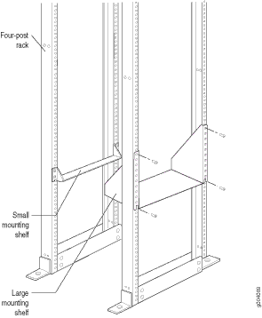
If you are installing the firewall in a front-mount four-post rack or cabinet, you must first install the large mounting shelf, followed by the small mounting shelf.
Table 1 specifies the holes in which you insert cage nuts and screws to install the mounting hardware required in a four-post or cabinet rack (an X indicates a mounting hole location). The hole distances are relative to one of the standard “U” divisions on the rack. The bottom of all mounting shelves is at 0.04 in. (0.02 U) above a “U” division.
Hole |
Distance Above “U” Division |
Large Shelf |
Small Shelf |
|
|---|---|---|---|---|
3 |
1.51 in. (3.8 cm) |
0.86 U |
X |
|
2 |
0.88 in. (2.2 cm) |
0.50 U |
X |
X |
1 |
0.25 in. (0.6 cm) |
0.14 U |
X |
|
To install the mounting shelves (see Figure 1):
- On the front rack rails, install cage nuts in the holes specified in Table 1 for the large shelf.
- On the front of each front rack rail, partially insert a mounting screw into the hole containing the lowest cage nut.
- Install the large shelf on the front rack rails. Rest the bottom slot of each ear on a mounting screw.
- Partially insert a mounting screw into the top hole in each ear of the large shelf.
- Tighten all the screws completely.
- On the rear rack rails, install cage nuts in the holes specified in Table 1 for the small shelf.
- On the back of each rear rack rail, partially insert a mounting screw into the hole containing the lowest cage nut.
- Install the small shelf on the back rack rails. Rest the bottom slot of each ear on a mounting screw. The small shelf installs on the back of the rear rails, extending toward the center of the rack. The bottom of the small shelf should align with the bottom of the large shelf.
- Partially insert screws into the open holes in the ears of the small shelf.
- Tighten all the screws completely.
Installing the SRX5800 Firewall Mounting Hardware in an Open-Frame Rack
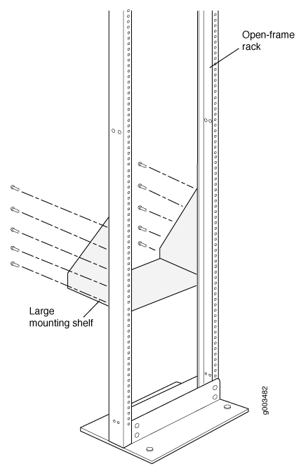
Before installing the firewall in an open-frame rack, install the large mounting shelf on the rack. The small mounting shelf is not needed.
If you are front-mounting the firewall, also remove the center-mounting brackets located on each side of the chassis.
Table 2 specifies the holes in which you insert screws to install the mounting hardware in an open-frame rack (an X indicates a mounting hole location). The hole distances are relative to one of the standard “U” divisions on the rack. For reference, the bottom of all mounting shelves is at 0.04 in. (0.02 U) above a “U” division.
Hole |
Distance Above “U” Division |
Large Shelf |
|
|---|---|---|---|
30 |
17.26 in. (43.8 cm) |
9.86 U |
X |
27 |
15.51 in. (39.4 cm) |
8.86 U |
X |
24 |
13.76 in. (34.9 cm) |
7.86 U |
X |
21 |
12.01 in. (30.5 cm) |
6.86 U |
X |
18 |
10.26 in. (26.0 cm) |
5.86 U |
X |
15 |
8.51 in. (21.6 cm) |
4.86 U |
X |
12 |
6.76 in. (17.1 cm) |
3.86 U |
X |
9 |
5.01 in. (12.7 cm) |
2.86 U |
X |
6 |
3.26 in. (8.3 cm) |
1.86 U |
X |
3 |
1.51 in. (3.8 cm) |
0.86 U |
X |
2 |
0.88 in. (2.2 cm) |
0.50 U |
X |
1 |
0.25 in. (0.6 cm) |
0.14 U |
|
To install the large mounting shelf (see Figure 2):
- On the rear of each rack rail, partially insert a mounting screw into the highest hole specified in Table 2 for the large shelf.
- Install the large shelf on the rack. Hang the shelf over the mounting screws using the keyhole slots located near the top of the large shelf flanges.
- Partially insert screws into the open holes in the ears of the large shelf.
- Tighten all the screws completely.
After the mounting hardware is installed, proceed to Installing the SRX5800 Firewall Chassis in the Rack.
Removing Components from the SRX5800 Chassis Before Installing It in the Rack
Before installing the firewall in the rack, you must first remove components from the chassis to make it light enough to safely maneuver into the rack. With components removed, the chassis weighs approximately 150 lb (68 kg). You reinstall the components into the chassis after it is installed in the rack.
- Removing the Power Supplies Before Installing the SRX5800 Firewall Chassis
- Removing the Cable Manager Before Installing the SRX5800 Firewall Chassis
- Removing Fan Trays Before Installing the SRX5800 Firewall Chassis
- Removing Cards Before Installing the SRX5800 Firewall Chassis
Removing the Power Supplies Before Installing the SRX5800 Firewall Chassis
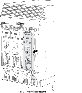
Remove the leftmost power supply first and then work your way to the right. To remove each AC or DC power supply (see Figure 3):
Removing the Cable Manager Before Installing the SRX5800 Firewall Chassis
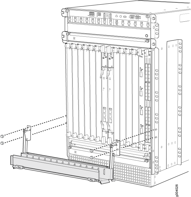
To remove the cable manager (see Figure 4):
- Attach an ESD grounding strap to your bare wrist, and connect the strap to one of the ESD points on the chassis.
- Using a 7/16-in. nut driver, unscrew the nuts on the corners of the cable manager.
- Grasp the bottom of the cable manager and pull it straight out from the studs on the front of the chassis.
Removing Fan Trays Before Installing the SRX5800 Firewall Chassis
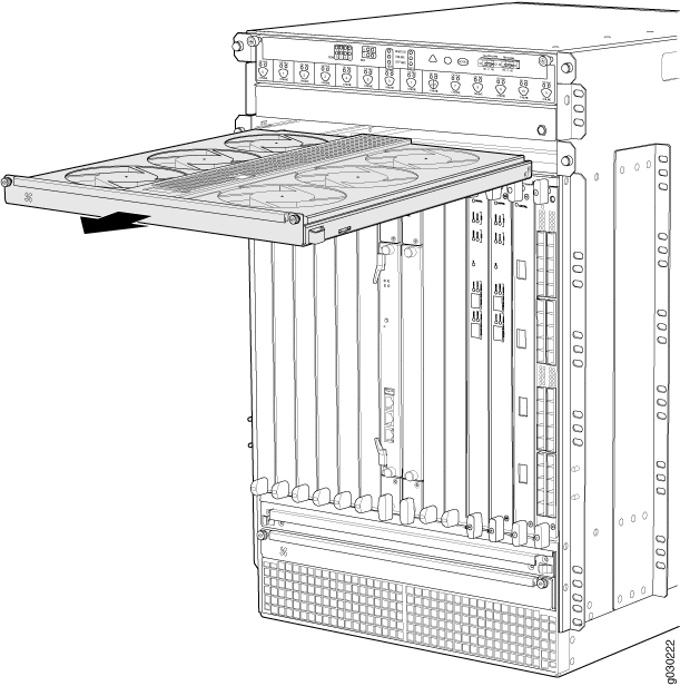
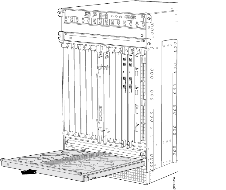
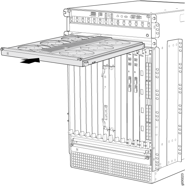
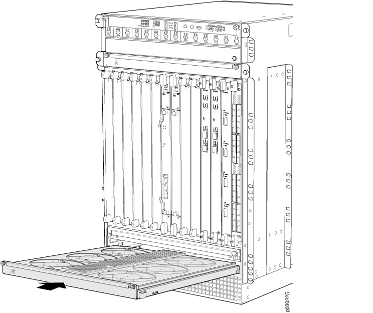
To remove the upper or bottom fan tray (see Figure 5 and Figure 6, which illustrate the upper and bottom fan trays):
- Attach an ESD grounding strap to your bare wrist, and connect the strap to one of the ESD points on the chassis.
- Loosen the captive screw on each side of the fan tray faceplate.
- Grasp both sides of the fan tray and pull it out approximately 1 to 3 inches.
- Press on the two latches located on the inside of the fan tray to release the fan tray from the chassis.
- Place one hand under the fan tray to support it and pull the fan tray completely out of the chassis.
Removing Cards Before Installing the SRX5800 Firewall Chassis
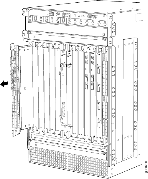
The firewall holds up to twelve cards (IOCs, Flex IOCs, MPCs, SCBs, and SPCs), which are installed horizontally in the front of the device. Each card weighs up to 18.3 lb (8.3 kg), be prepared to accept its full weight.
To remove a card (see Figure 7):
Installing the SRX5800 Firewall Chassis in the Rack
Because of the firewall’s size and weight—up to 400 lb (182 kg) depending on the configuration—you must install the firewall using a mechanical lift.
Before front mounting the firewall in a rack, have a qualified technician verify that the rack is strong enough to support the firewall's weight and is adequately supported at the installation site.
To install the firewall using a lift (see Figure 8):
- Ensure the rack is in its permanent location and is secured to the building. Ensure that the installation site allows adequate clearance for both airflow and maintenance.
- Load the firewall onto the lift, making sure it rests securely on the lift platform.
- Using the lift, position the firewall in front of the rack or cabinet, centering it in front of the mounting shelves.
- Lift the chassis approximately 0.75 in. above the surface of the mounting shelves and position it as close as possible to the shelves.
- Carefully slide the firewall onto the mounting shelves so that the bottom of the chassis and the mounting shelves overlap by approximately two inches.
- Slide the firewall onto the mounting shelves until the center-mounting brackets or front-mounting flanges contact the rack rails. The shelves ensure that the holes in the center-mounting brackets and the front-mounting flanges of the chassis align with the holes in the rack rails.
- Move the lift away from the rack.
- To install the firewall in an open-frame rack, install a mounting screw into each of the open mounting holes aligned with the rack, starting from the bottom.
- Visually inspect the alignment of the firewall. If the firewall is installed properly in the rack, all the mounting screws on one side of the rack should be aligned with the mounting screws on the opposite side and the firewall should be level.
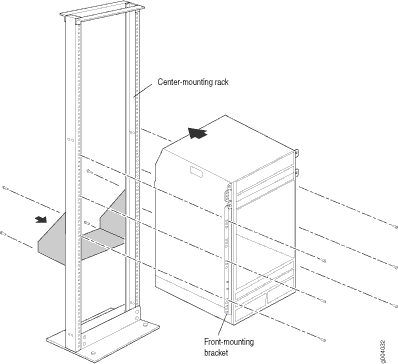
This illustration depicts the firewall being installed in an open-frame rack.
Reinstalling Components in the SRX5800 Firewall Chassis After Installing It in the Rack
After the firewall is installed in the rack, reinstall the removed components before booting and configuring the firewall. You reinstall components first in the rear of the chassis, and then in the front:
- Reinstalling Power Supplies After Installing the SRX5800 Firewall Chassis
- Reinstalling Fan Trays After Installing the SRX5800 Firewall Chassis
- Reinstalling Cards After Installing the SRX5800 Firewall Chassis
- Reinstalling the Cable Manager After Installing the SRX5800 Firewall Chassis
Reinstalling Power Supplies After Installing the SRX5800 Firewall Chassis
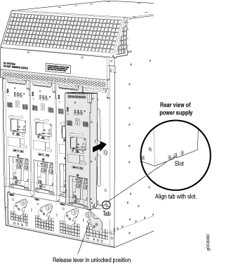
Reinstall the rightmost power supply first and then work your way to the left. To reinstall the AC or DC power supplies, follow this procedure for each power supply (see Figure 9, which shows the installation of the DC power supplies):
Reinstalling Fan Trays After Installing the SRX5800 Firewall Chassis
- Attach an ESD grounding strap to your bare wrist, and connect the strap to one of the ESD points on the chassis.
- Grasp the fan tray on each side and insert it straight into the chassis. Note the correct orientation by the "this side up" label on the top surface of the fan tray.
- Tighten the captive screws on each side of the fan tray faceplate to secure it in the chassis.
- Lower the standard cable manager back into position, if necessary.
Reinstalling Cards After Installing the SRX5800 Firewall Chassis
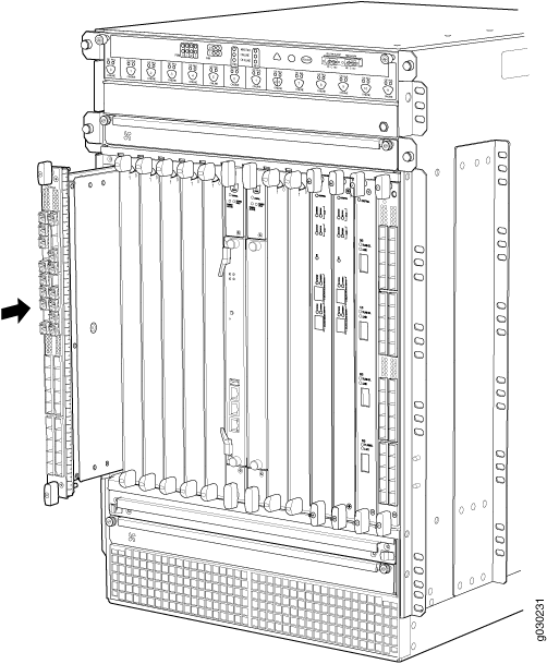
To reinstall cards (IOCs, Flex IOCs, MPCs, SPCs, and SCBs (see Figure 12):
Reinstalling the Cable Manager After Installing the SRX5800 Firewall Chassis
To reinstall the cable manager (see Figure 13):
- Attach an ESD grounding strap to your bare wrist, and connect the strap to one of the ESD points on the chassis.
- Position the cable manager on the studs on the lower front of the chassis.
- Insert the nuts on the corners in the cable manager onto the studs on the chassis.
- Using a 7/16-in. nut driver, tighten the nuts securely.

