- play_arrow Common Configuration for All VPNs
- play_arrow VPNs Overview
- play_arrow Assigning Routing Instances to VPNs
- play_arrow Distributing Routes in VPNs
- play_arrow Distributing VPN Routes with Target Filtering
- Configuring BGP Route Target Filtering for VPNs
- Example: BGP Route Target Filtering for VPNs
- Example: Configuring BGP Route Target Filtering for VPNs
- Configuring Static Route Target Filtering for VPNs
- Understanding Proxy BGP Route Target Filtering for VPNs
- Example: Configuring Proxy BGP Route Target Filtering for VPNs
- Example: Configuring an Export Policy for BGP Route Target Filtering for VPNs
- Reducing Network Resource Use with Static Route Target Filtering for VPNs
- play_arrow Configuring Forwarding Options for VPNs
- play_arrow Configuring Graceful Restart for VPNs
- play_arrow Configuring Class of Service for VPNs
- play_arrow Pinging VPNs
-
- play_arrow Common Configuration for Layer 2 VPNs and VPLS
- play_arrow Overview
- play_arrow Layer 2 VPNs Configuration Overview
- play_arrow Configuring Layer 2 Interfaces
- play_arrow Configuring Path Selection for Layer 2 VPNs and VPLS
- play_arrow Creating Backup Connections with Redundant Pseudowires
- play_arrow Configuring Class of Service for Layer 2 VPNs
- play_arrow Monitoring Layer 2 VPNs
- Configuring BFD for Layer 2 VPN and VPLS
- BFD Support for VCCV for Layer 2 VPNs, Layer 2 Circuits, and VPLS
- Configuring BFD for VCCV for Layer 2 VPNs, Layer 2 Circuits, and VPLS
- Connectivity Fault Management Support for EVPN and Layer 2 VPN Overview
- Configure a MEP to Generate and Respond to CFM Protocol Messages
-
- play_arrow Configuring Group VPNs
- play_arrow Configuring Public Key Infrastructure
- play_arrow Configuring Digital Certificate Validation
- play_arrow Configuring a Device for Certificate Chains
- play_arrow Managing Certificate Revocation
-
- play_arrow Configuring VPWS VPNs
- play_arrow Overview
- play_arrow Configuring VPWS VPNs
- Understanding FEC 129 BGP Autodiscovery for VPWS
- Example: Configuring FEC 129 BGP Autodiscovery for VPWS
- Example: Configuring MPLS Egress Protection Service Mirroring for BGP Signaled Layer 2 Services
- Understanding Multisegment Pseudowire for FEC 129
- Example: Configuring a Multisegment Pseudowire
- Configuring the FAT Flow Label for FEC 128 VPWS Pseudowires for Load-Balancing MPLS Traffic
- Configuring the FAT Flow Label for FEC 129 VPWS Pseudowires for Load-Balancing MPLS Traffic
-
- play_arrow Configuring VPLS
- play_arrow Overview
- play_arrow VPLS Configuration Overview
- play_arrow Configuring Signaling Protocols for VPLS
- VPLS Routing and Virtual Ports
- BGP Signaling for VPLS PE Routers Overview
- Control Word for BGP VPLS Overview
- Configuring a Control Word for BGP VPLS
- BGP Route Reflectors for VPLS
- Interoperability Between BGP Signaling and LDP Signaling in VPLS
- Configuring Interoperability Between BGP Signaling and LDP Signaling in VPLS
- Example: VPLS Configuration (BGP Signaling)
- Example: VPLS Configuration (BGP and LDP Interworking)
- play_arrow Assigning Routing Instances to VPLS
- Configuring VPLS Routing Instances
- Configuring a VPLS Routing Instance
- Support of Inner VLAN List and Inner VLAN Range for Qualified BUM Pruning on a Dual-Tagged Interface for a VPLS Routing Instance Overview
- Configuring Qualified BUM Pruning for a Dual-Tagged Interface with Inner VLAN list and InnerVLAN range for a VPLS Routing Instance
- Configuring a Layer 2 Control Protocol Routing Instance
- PE Router Mesh Groups for VPLS Routing Instances
- Configuring VPLS Fast Reroute Priority
- Specifying the VT Interfaces Used by VPLS Routing Instances
- Understanding PIM Snooping for VPLS
- Example: Configuring PIM Snooping for VPLS
- VPLS Label Blocks Operation
- Configuring the Label Block Size for VPLS
- Example: Building a VPLS From Router 1 to Router 3 to Validate Label Blocks
- play_arrow Associating Interfaces with VPLS
- play_arrow Configuring Pseudowires
- Configuring Static Pseudowires for VPLS
- VPLS Path Selection Process for PE Routers
- BGP and VPLS Path Selection for Multihomed PE Routers
- Dynamic Profiles for VPLS Pseudowires
- Use Cases for Dynamic Profiles for VPLS Pseudowires
- Example: Configuring VPLS Pseudowires with Dynamic Profiles—Basic Solutions
- Example: Configuring VPLS Pseudowires with Dynamic Profiles—Complex Solutions
- Configuring the FAT Flow Label for FEC 128 VPLS Pseudowires for Load-Balancing MPLS Traffic
- Configuring the FAT Flow Label for FEC 129 VPLS Pseudowires for Load-Balancing MPLS Traffic
- Example: Configuring H-VPLS BGP-Based and LDP-Based VPLS Interoperation
- Example: Configuring BGP-Based H-VPLS Using Different Mesh Groups for Each Spoke Router
- Example: Configuring LDP-Based H-VPLS Using a Single Mesh Group to Terminate the Layer 2 Circuits
- Example: Configuring H-VPLS With VLANs
- Example: Configuring H-VPLS Without VLANs
- Configure Hot-Standby Pseudowire Redundancy in H-VPLS
- Sample Scenario of H-VPLS on ACX Series Routers for IPTV Services
- play_arrow Configuring Multihoming
- VPLS Multihoming Overview
- Advantages of Using Autodiscovery for VPLS Multihoming
- Example: Configuring FEC 129 BGP Autodiscovery for VPWS
- Example: Configuring BGP Autodiscovery for LDP VPLS
- Example: Configuring BGP Autodiscovery for LDP VPLS with User-Defined Mesh Groups
- VPLS Multihoming Reactions to Network Failures
- Configuring VPLS Multihoming
- Example: VPLS Multihoming, Improved Convergence Time
- Example: Configuring VPLS Multihoming (FEC 129)
- Next-Generation VPLS for Multicast with Multihoming Overview
- Example: Next-Generation VPLS for Multicast with Multihoming
- play_arrow Configuring Point-to-Multipoint LSPs
- play_arrow Configuring Inter-AS VPLS and IRB VPLS
- play_arrow Configuring Load Balancing and Performance
- Configuring VPLS Load Balancing
- Configuring VPLS Load Balancing Based on IP and MPLS Information
- Configuring VPLS Load Balancing on MX Series 5G Universal Routing Platforms
- Example: Configuring Loop Prevention in VPLS Network Due to MAC Moves
- Understanding MAC Pinning
- Configuring MAC Pinning on Access Interfaces for Bridge Domains
- Configuring MAC Pinning on Trunk Interfaces for Bridge Domains
- Configuring MAC Pinning on Access Interfaces for Bridge Domains in a Virtual Switch
- Configuring MAC Pinning on Trunk Interfaces for Bridge Domains in a Virtual Switch
- Configuring MAC Pinning for All Pseudowires of the VPLS Routing Instance (LDP and BGP)
- Configuring MAC Pinning on VPLS CE Interface
- Configuring MAC Pinning for All Pseudowires of the VPLS Site in a BGP-Based VPLS Routing Instance
- Configuring MAC Pinning on All Pseudowires of a Specific Neighbor of LDP-Based VPLS Routing Instance
- Configuring MAC Pinning on Access Interfaces for Logical Systems
- Configuring MAC Pinning on Trunk Interfaces for Logical Systems
- Configuring MAC Pinning on Access Interfaces in Virtual Switches for Logical Systems
- Configuring MAC Pinning on Trunk Interfaces in Virtual Switches for Logical Systems
- Configuring MAC Pinning for All Pseudowires of the VPLS Routing Instance (LDP and BGP) for Logical Systems
- Configuring MAC Pinning on VPLS CE Interface for Logical Systems
- Configuring MAC Pinning for All Pseudowires of the VPLS Site in a BGP-Based VPLS Routing Instance for Logical Systems
- Configuring MAC Pinning on All Pseudowires of a Specific Neighbor of LDP-Based VPLS Routing Instance for Logical Systems
- Example: Prevention of Loops in Bridge Domains by Enabling the MAC Pinnning Feature on Access Interfaces
- Example: Prevention of Loops in Bridge Domains by Enabling the MAC Pinnning Feature on Trunk Interfaces
- Configuring Improved VPLS MAC Address Learning on T4000 Routers with Type 5 FPCs
- Understanding Qualified MAC Learning
- Qualified Learning VPLS Routing Instance Behavior
- Configuring Qualified MAC Learning
- play_arrow Configuring Class of Service and Firewall Filters in VPLS
- play_arrow Monitoring and Tracing VPLS
-
- play_arrow Connecting Layer 2 VPNs and Circuits to Other VPNs
- play_arrow Connecting Layer 2 VPNs to Other VPNs
- play_arrow Connecting Layer 2 Circuits to Other VPNs
- Using the Layer 2 Interworking Interface to Interconnect a Layer 2 Circuit to a Layer 2 VPN
- Applications for Interconnecting a Layer 2 Circuit with a Layer 2 Circuit
- Example: Interconnecting a Layer 2 Circuit with a Layer 2 VPN
- Example: Interconnecting a Layer 2 Circuit with a Layer 2 Circuit
- Applications for Interconnecting a Layer 2 Circuit with a Layer 3 VPN
- Example: Interconnecting a Layer 2 Circuit with a Layer 3 VPN
-
- play_arrow Configuration Statements and Operational Commands
Configuring Egress Protection Service Mirroring for BGP Signaled Layer 2 Services
Starting in Junos OS Release 14.2, Junos OS supports the restoration of egress traffic when there is a link or node failure in the egress PE node. If there is a link or node failure in the core network, a protection mechanism such as MPLS fast reroute can be triggered on the transport LSPs between the PE routers to repair the connection within tens of milliseconds. An egress protection LSP addresses the problem of a node-link failure at the edge of the network (for example, a failure of a PE router).
Figure 1 shows a simplified topology of the use case that explains this feature.

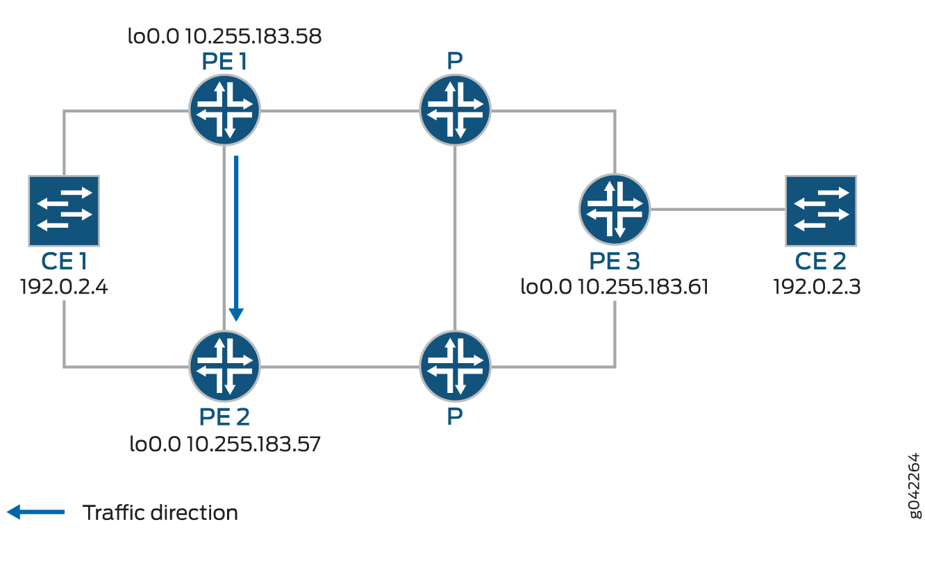
CE1 is multihomed to PE1 and PE2. There are two paths connecting CE1 and CE2. The working path is CE2-PE3-P-PE1-CE1, via pseudowire PW21. The protecting path is CE2-PE3-P-PE2-CE1, via pseudowire PW22 Traffic is flowing through the working path under normal circumstances. When the end-to-end OAM between CE1 and CE2 detects failure on the working path, traffic will be switched from the working path to the protecting path. The end-to-end failure detection and recovery relies on control plane hence should be relatively slow. To achieve faster protection, local repair mechanisms similar to those used by MPLS fast reroute should be used. In Figure 1 above, if link or node failed in the core network (like link failure on P-PE1, P-PE3, or node failure on P), the MPLS fast reroute will happen on the transport LSPs between PE1 and PE3. The failure could be locally repaired within tens of milliseconds. However, if link or node failure happens at the edge (like link failure on PE3-CE2 or node failure on PE3), there is no local repair currently so we have to rely on the CE1-CE2 end-to-end protection to repair the failure.
Device CE2—Traffic origin
Router PE3—Ingress PE router
Router PE1— (Primary) Egress PE router
Router PE2—Protector PE router
Device CE1—Traffic destination
When the link between CE1– PE1 goes downs, PE1 will briefly redirect that traffic towards CE1, to PE2. PE2 forwards it to CE1 until ingress router PE3 recalculates to forward the traffic to PE2.
Initially the traffic direction was; CE2 – PE3 – P – PE1 – CE1.
When the link between CE1– PE1 goes down, the traffic will be; CE2 – PE3 – P – PE1 – PE2 –CE1. PE3 then recalculates the path; CE2 – PE3 – P – PE2 – CE1.
Change History Table
Feature support is determined by the platform and release you are using. Use Feature Explorer to determine if a feature is supported on your platform.