Example: Configure MPLS-Based Layer 2 VPNs
This example shows how to configure and validate an MPLS-based Layer 2 VPN on routers or switches running Junos OS.
Our content testing team has validated and updated this example.
You can deploy an MPLS-based Layer 2 virtual private network using routers and switches running Junos OS to interconnect customer sites with Layer 2 connectivity. Layer 2 VPNs give customers complete control over their choice of transport and routing protocols.
MPLS-based VPNs require baseline MPLS functionality in the provider network. Once basic MPLS is operational, you are able to configure VPNs that use Label-switched paths (LSPs) for transport over the provider’s core.
The addition of VPN services does not affect the basic MPLS switching operations in the provider network. In fact, the provider (P) devices require only a baseline MPLS configuration because they are not VPN aware. VPN state is maintained only on the PE devices. This is a key reason why MPLS-based VPNs are so scalable.
Requirements
This example uses the following hardware and software components:
Junos OS Release 15.1 or later
Revalidated on Junos OS Release 20.1R1
Two Provider edge (PE) devices
One provider (P) device
Two customer edge (CE) devices
The example focuses on how to add Layer 2 VPN to a pre-existing MPLS baseline. A basic MPLS configuration is provided in case your network does not already have MPLS deployed.
To support MPLS-based VPNs the underlying MPLS baseline must provide the following functionality:
Core-facing and loopback interfaces operational with MPLS family support
An interior gateway protocol such as OSPF or IS-IS to provide reachability between the loopback addresses of the provider (P and PE) devices
An MPLS signalling protocol such as LDP or RSVP to signal LSPs
LSPs established between PE device loopback addresses
LSPs are needed between each pair of PE devices that participate
in a given VPN. Its a good idea to build LSPs between all PE devices
to accommodate future VPN growth. You configure LSPs at the [edit
protocols mpls] hierarchy level. Unlike an MPLS configuration
for circuit cross-connect (CCC) , you do not need to manually associate
the LSP with the PE device’s customer-facing (edge) interface.
Instead, Layer 2 VPNs use BGP signalling to convey Layer 2 site reachability.
This BGP signaling automates the mapping of remote Layer 2 VPN sites
to LSP forwarding next hops. This means that with a Layer 2 VPN explicit
mapping of an LSP to a PE device’s edge-facing interface is
not required.
For details on CCC, refer to Configuring an MPLS-Based VLAN CCC Using a Layer 2 Circuit.
Overview and Topology
A Layer 2 VPN provides complete separation between the provider and customer networks. The benefits of a Layer 2 VPN include support for nonstandard transport protocols and the isolation of link addressing and routing protocol operation between the customer and provider networks.
Definition of a VPN involves changes to the local and remote PE devices only. No additional configuration is needed on the provider devices (aside from baseline MPLS support), because these devices only provide basic MPLS switching functions. The CE devices do not use MPLS. They require only a basic interface, and if desired, protocol configuration, to operate over the Layer 2 VPN. For a Layer 2 VPN you configure the CE devices as if they were attached to a shared link.
Once an MPLS baseline is in place, you must configure the following functionality on the PE devices to establish an MPLS-based Layer 2 VPN:
A BGP group with
family l2vpn signalingA routing instance with instance type
l2vpnThe customer-facing interfaces on the PE devices must be configured as follows:
Specify
ethernet-cccorvlan-cccphysical layer encapsulation depending on whether VLAN tagging is in use.Configure a matching encapsulation type in the routing instance configuration.
Configure the logical interface (unit) used for the Layer 2 VPN with
family ccc.
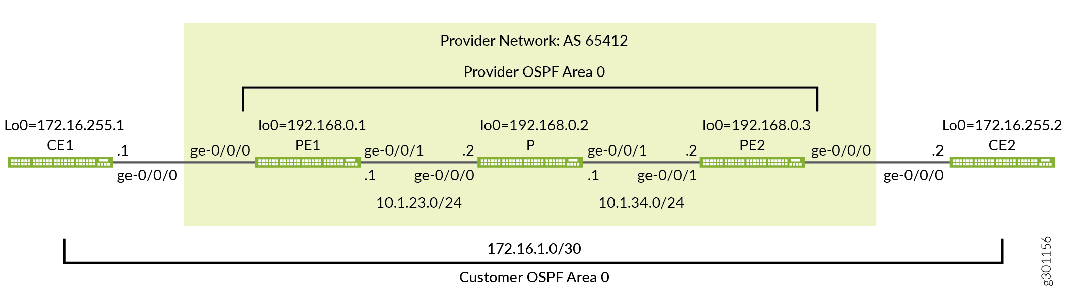
Figure 1 provides the topology for this MPLS-based Layer 2 VPN example. The figure details the interface names, IP addressing, and protocols used in the provider network. It also highlights the end-to-end nature of the CE device addressing and protocol stack operation. Unlike a Layer 3 VPN, CE device operation is opaque to the provider network in a Layer 2 VPN. There is no peering relationship between the CE devices and the provider network. As a result you expect the CE devices to form an OSPF adjacency across, not to, the provider network.
Quick Configurations
Use the configurations in this section to quickly get your MPLS-based Layer 2 VPN up and running. The configurations include a functional MPLS baseline to support your Layer 2 VPN. This example focuses on the VPN aspects of the configuration. Refer to the following links for additional information on the baseline MPLS functionality used in this example:
CLI Quick Configuration
The device configurations omit the management interface, static routes, system logging, system services, and user login information. These parts of the configuration vary by location and are not directly related to MPLS or VPN functionality.
Edit the following commands as needed for the specifics of your environment and paste them into the local CE (CE1) device terminal window:
The complete configuration for the CE1 device.
set system host-name ce1
set interfaces ge-0/0/0 description "Link from CE1 to PE1"
set interfaces ge-0/0/0 unit 0 family inet address 172.16.1.1/30
set interfaces lo0 unit 0 family inet address 172.16.255.1/32
set protocols ospf area 0.0.0.0 interface lo0.0
set protocols ospf area 0.0.0.0 interface ge-0/0/0.0
Edit the following commands as needed for the specifics of your environment and paste them into the local PE (PE1) device terminal window:
The complete configuration for PE1 device.
set system host-name pe1
set interfaces ge-0/0/0 description "Link from PE1 to CE1"
set interfaces ge-0/0/0 encapsulation ethernet-ccc
set interfaces ge-0/0/0 unit 0 family ccc
set interfaces ge-0/0/1 description "Link from PE1 to P-router"
set interfaces ge-0/0/1 mtu 4000
set interfaces ge-0/0/1 unit 0 family inet address 10.1.23.1/24
set interfaces ge-0/0/1 unit 0 family mpls
set interfaces lo0 unit 0 family inet address 192.168.0.1/32
set routing-instances l2vpn1 protocols l2vpn interface ge-0/0/0.0 description "EDGE LINK BETWEEN PE1 AND CE1"
set routing-instances l2vpn1 protocols l2vpn site CE-1 interface ge-0/0/0.0 remote-site-id 2
set routing-instances l2vpn1 protocols l2vpn site CE-1 site-identifier 1
set routing-instances l2vpn1 protocols l2vpn encapsulation-type ethernet
set routing-instances l2vpn1 instance-type l2vpn
set routing-instances l2vpn1 interface ge-0/0/0.0
set routing-instances l2vpn1 route-distinguisher 192.168.0.1:12
set routing-instances l2vpn1 vrf-target target:65412:12
set routing-options autonomous-system 65412
set protocols bgp group ibgp type internal
set protocols bgp group ibgp local-address 192.168.0.1
set protocols bgp group ibgp family l2vpn signaling
set protocols bgp group ibgp neighbor 192.168.0.3
set protocols mpls label-switched-path lsp_to_pe2 to 192.168.0.3
set protocols mpls interface ge-0/0/1.0
set protocols ospf traffic-engineering
set protocols ospf area 0.0.0.0 interface lo0.0
set protocols ospf area 0.0.0.0 interface ge-0/0/1.0
set protocols rsvp interface lo0.0
set protocols rsvp interface ge-0/0/1.0
The complete configuration for the P device.
set system host-name p
set interfaces ge-0/0/0 description "Link from P-router to PE1"
set interfaces ge-0/0/0 mtu 4000
set interfaces ge-0/0/0 unit 0 family inet address 10.1.23.2/24
set interfaces ge-0/0/0 unit 0 family mpls
set interfaces ge-0/0/1 description "Link from P-router to PE2"
set interfaces ge-0/0/1 mtu 4000
set interfaces ge-0/0/1 unit 0 family inet address 10.1.34.1/24
set interfaces ge-0/0/1 unit 0 family mpls
set interfaces lo0 unit 0 family inet address 192.168.0.2/32
set protocols mpls interface ge-0/0/0.0
set protocols mpls interface ge-0/0/1.0
set protocols ospf traffic-engineering
set protocols ospf area 0.0.0.0 interface lo0.0
set protocols ospf area 0.0.0.0 interface ge-0/0/0.0
set protocols ospf area 0.0.0.0 interface ge-0/0/1.0
set protocols rsvp interface lo0.0
set protocols rsvp interface ge-0/0/0.0
set protocols rsvp interface ge-0/0/1.0
The complete configuration for the PE2 device.
set system host-name pe2
set interfaces ge-0/0/0 description "Link from PE2 to CE2"
set interfaces ge-0/0/0 encapsulation ethernet-ccc
set interfaces ge-0/0/0 unit 0 family ccc
set interfaces ge-0/0/1 description "Link from PE2 to P-router"
set interfaces ge-0/0/1 mtu 4000
set interfaces ge-0/0/1 unit 0 family inet address 10.1.34.2/24
set interfaces ge-0/0/1 unit 0 family mpls
set interfaces lo0 unit 0 family inet address 192.168.0.3/32
set routing-instances l2vpn1 protocols l2vpn interface ge-0/0/0.0 description "EDGE LINK BETWEEN PE2 AND CE2"
set routing-instances l2vpn1 protocols l2vpn site CE-2 interface ge-0/0/0.0 remote-site-id 1
set routing-instances l2vpn1 protocols l2vpn site CE-2 site-identifier 2
set routing-instances l2vpn1 protocols l2vpn encapsulation-type ethernet
set routing-instances l2vpn1 instance-type l2vpn
set routing-instances l2vpn1 interface ge-0/0/0.0
set routing-instances l2vpn1 route-distinguisher 192.168.0.3:12
set routing-instances l2vpn1 vrf-target target:65412:12
set routing-options autonomous-system 65412
set protocols bgp group ibgp type internal
set protocols bgp group ibgp local-address 192.168.0.3
set protocols bgp group ibgp family l2vpn signaling
set protocols bgp group ibgp neighbor 192.168.0.1
set protocols mpls label-switched-path lsp_to_pe1 to 192.168.0.1
set protocols mpls interface ge-0/0/1.0
set protocols ospf traffic-engineering
set protocols ospf area 0.0.0.0 interface lo0.0
set protocols ospf area 0.0.0.0 interface ge-0/0/1.0
set protocols rsvp interface lo0.0
set protocols rsvp interface ge-0/0/1.0
The complete configuration for the CE2 device.
set system host-name ce2
set interfaces ge-0/0/0 description "Link from CE2 to PE2"
set interfaces ge-0/0/0 unit 0 family inet address 172.16.1.2/30
set interfaces lo0 unit 0 family inet address 172.16.255.2/32
set protocols ospf area 0.0.0.0 interface lo0.0
set protocols ospf area 0.0.0.0 interface ge-0/0/0.0
Be sure to commit the configuration changes on all devices when satisfied with your work. Congratulations on your new MPLS-based Layer 2 VPN! Refer to the Verification section for the steps needed to confirm your VPN is working as expected.
Configure the Local PE (PE1) Device for a MPLS-Based Layer 2 VPN
This section covers the steps needed to configure the PE1 device for this example. Refer to the Example: Configure MPLS-Based Layer 2 VPNs section for the CE device and P device configurations used in this example.
Configure the MPLS Baseline (if Needed)
Before you configure the Layer 2 VPN make sure the PE device has a working MPLS baseline. If you already having a an MPLS baseline you can skip to the step-by-step procedure to add the Layer 2 VPN to the local PE device.
-
Configure the hostname.
[edit]
user@pe1# set system host-name pe1
-
Configure the interfaces.
[edit]
user@pe1# set interfaces ge-0/0/1 description "Link from PE1 to P-router"
[edit]
user@pe1# set interfaces ge-0/0/1 mtu 4000
[edit]
user@pe1# set interfaces ge-0/0/1 unit 0 family inet address 10.1.23.1/24
[edit]
user@pe1# set interfaces ge-0/0/1 unit 0 family mpls
[edit]
user@pe1# set interfaces lo0 unit 0 family inet address 192.168.0.1/32
CAUTION:Layer 2 VPNs don’t support fragmentation in the provider network. It is critical that the provider network supports the largest frame that the CE devices can generate after the MPLS and virtual routing and forwarding (VRF) labels are added by the PE devices. This example leaves the CE devices at the default 1500-byte maximum transmission unit (MTU) while configuring the provider core to support a 4000 byte MTU. This configuration avoids discards by ensuring the CE devices cannot exceed the MTU in the provider’s network.
-
Configure the protocols.
Note:Traffic engineering is supported for RSVP-signaled LSPs but is not required for basic MPLS switching or VPN deployment. The provided MPLS baseline uses RSVP to signal LSPs, and enables traffic engineering for OSPF. However, no path constraints are configured so you expect the LSPs to be routed over the interior gateway protocol’s shortest path.
[edit
]user@pe1# set protocols ospf area 0.0.0.0 interface lo0.0
[edit]
user@pe1# set protocols ospf area 0.0.0.0 interface ge-0/0/1.0
[edit]
user@pe1# set protocols ospf traffic-engineering
[edit]
user@pe1# set protocols mpls interface ge-0/0/1.0
[edit]
user@pe1# set protocols rsvp interface lo0.0
[edit]
user@pe1# set protocols rsvp interface ge-0/0/1.0
-
Define the LSP to the remote PE device’s loopback address.
[edit]
user@pe1#  set protocols mpls label-switched-path lsp_to_pe2 to 192.168.0.3
Procedure
Step-by-Step Procedure
Follow these steps to configure the PE1 device for a Layer 2 VPN.
Configure the edge-facing interface. Specify a physical encapsulation type of
ethernet-cccwithfamily cccon unit 0. This is the only valid unit number for an untagged Ethernet interface. If you are using VLAN tagging specifyvlan-cccencapsulation and add the CCC family to the desired unit(s).Tip:You can configure both an MPLS-based Layer 2 VPN and an MPLS-based Layer 3 VPN on the same PE device. However, you cannot configure the same customer edge-facing interface to support both a Layer 2 VPN and a Layer 3 VPN.
[edit]user@pe1# set interfaces ge-0/0/0 encapsulation ethernet-ccc
[edit]
user@pe1# set interfaces ge-0/0/0 unit 0 family ccc
[edit]
user@pe1# set interfaces ge-0/0/0 description "Link from PE1 to CE1"
Note:A Layer 2 VPN requires that the PE device’s edge-facing interfaces be configured with CCC encapsulation at the physical device level with the CCC family configured at the unit level. The provider devices are configured in the same way whether you are deploying CCC, an MPLS-based Layer 2 VPN, or an MPLS-based Layer 3 VPN. This is because they have no edge-facing interfaces or VPN awareness.
Configure a BGP group for the peering between the local and remote PE devices. Use the PE device’s loopback address as the local address and enable
family l2vpn signaling.[edit protocols bgp] user@pe1# set group ibgp local-address 192.168.0.1 family l2vpn signaling
Configure the BGP group type as internal.
[edit protocols bgp]
user@pe1# set group ibgp type internal
Configure the remote PE device’s loopback address as a BGP neighbor.
[edit protocols bgp]
user@pe1# set group ibgp neighbor 192.168.0.3
Configure the BGP autonomous system number.
[edit routing-options]
user@pe1# set autonomous-system 65412
Configure the routing instance. Start by specifying the instance name l2vpn1, with an
instance-typeofl2vpn.[edit routing-instances] user@pe1# set l2vpn1 instance-type l2vpn
Configure the PE device’s customer-facing interface to belong to the routing instance.
[edit routing-instances]
user@pe1# set l2vpn1 interface ge-0/0/0
Configure the routing instance’s route distinguisher. This setting is used to distinguish the routes sent from a particular VRF on a particular PE device. It should be unique for each routing instance on each PE device.
[edit routing-instances]
user@pe1# set l2vpn1 route-distinguisher 192.168.0.1:12
Configure the instance’s virtual routing and forwarding (VRF) table route target. The
vrf-targetstatement adds the specified community tag to all advertised routes while automatically matching the same value for route import. Configuring matching route targets on the PE devices that share a given VPN is required for proper route exchange.[edit routing-instances] user@pe1# set l2vpn1 vrf-target target:65412:12
Note:You can create more complex policies by explicitly configuring VRF import and export policies using the import and export options. See vrf-import and vrf-export for details.
Configure the
l2vpnprotocol in the instance and specify the encapsulation that is used on the edge-facing link. If the edge interface is VLAN tagged, be sure to specifyethernet-vlan.[edit routing-instances] user@pe1# set l2vpn1 protocols l2vpn encapsulation-type ethernet
Add the edge-facing interface under the instance’s
l2vpnstanza along with a description.[edit routing-instances] user@pe1# set l2vpn1 protocols l2vpn interface ge-0/0/0.0 description "L2vpn Link Between PE1 and CE1"
Configure the Layer 2 VPN site information and associate the edge-facing interface with the local customer site.
[edit routing-instances]
user@pe1# set l2vpn1 protocols l2vpn site CE-1 site-identifier 1 interface ge-0/0/0.0 remote-site-id 2
Note:In this example, the site ID for the PE1 device is 1 and the site ID for the PE2 device is 2. For the local PE device (PE1), the remote site is correctly configured with a
remote-site-idvalue of 2.Commit your changes at the PE1 device and return to CLI operational mode.
[edit]
user@pe1# commit and-quit
Results
Display the results of the configuration on the PE1 device. The output reflects only the functional configuration added in this example.
user@pe1> show configuration
interfaces {
    ge-0/0/0 {
        description "Link from PE1 to CE1";
        encapsulation ethernet-ccc;
        unit 0 {
            family ccc;
        }
    }
    ge-0/0/1 {
        description "Link from PE1 to P-router";
        mtu 4000;
        unit 0 {
            family inet {
                address 10.1.23.1/24;
            }
            family mpls;
        }
    }
    lo0 {
        unit 0 {
            family inet {
                address 192.168.0.1/32;
            }
        }
    }
}
routing-instances {
    l2vpn1 {
        protocols {
            l2vpn {
                interface ge-0/0/0.0 {
                    description "L2vpn Link Between PE1 and CE1" ;
                }
                site CE-1 {
                    interface ge-0/0/0.0 {
                        remote-site-id 2;
                    }
                    site-identifier 1;
                }
                encapsulation-type ethernet;
            }
        }
        instance-type l2vpn;
        interface ge-0/0/0.0;
        route-distinguisher 192.168.0.1:12;
        vrf-target target:65412:12;
    }
}
routing-options {
    autonomous-system 65412;
}
protocols {
    bgp {
        group ibgp {
            type internal;
            local-address 192.168.0.1;
            family l2vpn {
                signaling;
            }
            neighbor 192.168.0.3;
        }
    }
    mpls {
        label-switched-path lsp_to_pe2 {
            to 192.168.0.3;
        }
        interface ge-0/0/1.0;
    }
    ospf {
        traffic-engineering;
        area 0.0.0.0 {
            interface lo0.0;
            interface ge-0/0/1.0;
        }
    }
    rsvp {
        interface lo0.0;
        interface ge-0/0/1.0;
    }
}
Configure the Remote PE (PE2) Device for a MPLS-Based Layer 2 VPN
This section covers the steps needed to configure the PE2 device for this example. Refer to the Example: Configure MPLS-Based Layer 2 VPNs section for the CE device and P device configurations used in this example.
Configure the MPLS Baseline (if Needed)
Before you configure the Layer 2 VPN make sure the PE device has a working MPLS baseline. If you already having an MPLS baseline you can skip to the step-by-step procedure to add the Layer 2 VPN to the local PE device.
-
Configure the hostname.
[edit]
user@pe2# set system host-name pe2
-
Configure the interfaces.
[edit]
user@pe2# set interfaces ge-0/0/1 description "Link from PE2 to P-router"
[edit]
user@pe2# set interfaces ge-0/0/1 mtu 4000
[edit]
user@pe2# set interfaces ge-0/0/1 unit 0 family inet address 10.1.34.2/24
[edit]
user@pe2# set interfaces ge-0/0/1 unit 0 family mpls
[edit]
user@pe2# set interfaces lo0 unit 0 family inet address 192.168.0.3/32
CAUTION:Layer 2 VPNs don’t support fragmentation in the provider network. It is critical that the provider network supports the largest frame that the CE devices can generate after the MPLS and virtual routing and forwarding (VRF) labels are added by the PE devices. This example leaves the CE devices at the default 1500-byte maximum transmission unit (MTU) while configuring the provider core to support a 4000 byte MTU. This configuration avoids discards by ensuring the CE devices cannot exceed the MTU in the provider’s network.
-
Configure the protocols.
Note:Traffic engineering is supported for RSVP-signaled LSPs but is not required for basic MPLS switching or VPN deployment. The provided MPLS baseline uses RSVP to signal LSPs, and enables traffic engineering for OSPF. However, no path constraints are configured so you expect the LSPs to be routed over the interior gateway protocol’s shortest path.
[edit]
user@pe2# set protocols ospf area 0.0.0.0 interface lo0.0
[edit]
user@pe2# set protocols ospf area 0.0.0.0 interface ge-0/0/1.0
[edit]
user@pe2# set protocols ospf traffic-engineering
[edit]
user@pe2# set protocols mpls interface ge-0/0/1.0
[edit]
user@pe2# set protocols rsvp interface lo0.0
[edit]
user@pe2# set protocols rsvp interface ge-0/0/1.0
-
Define the LSP to the remote PE device’s loopback address.
[edit]
user@pe2#  set protocols mpls label-switched-path lsp_to_pe1 to 192.168.0.1
Procedure
Step-by-Step Procedure
Follow these steps to configure the PE2 device for a Layer 2 VPN.
Configure the edge-facing interface encapsulation and family. Recall this is an untagged interface, therefore only unit 0 is valid for the
cccfamily.[edit]user@pe2# set interfaces ge-0/0/0 encapsulation ethernet-ccc [edit] user@pe2# set interfaces ge-0/0/0 unit 0 family ccc [edit] user@pe1# set interfaces ge-0/0/0 description "Link from PE2 to CE2"
Configure a BGP group. Specify the PE device’s loopback address as the local address and enable
family l2vpn signaling.[edit protocols bgp] user@pe2# set group ibgp local-address 192.168.0.3 family l2vpn signaling
Configure the BGP group type as internal.
[edit protocols bgp]
user@pe2# set group ibgp type internal
Configure the PE1 device as a BGP neighbor. Be sure to specify PE1’s loopback address as the BGP neighbor.
[edit protocols bgp]
user@pe2# set group ibgp neighbor 192.168.0.1
Configure the BGP autonomous system number.
[edit routing-options]
user@pe2# set autonomous-system 65412
Configure the routing instance. Start by specifying the instance name l2vpn1 with an
instance-typeofl2vpn.[edit routing-instances] user@pe2# set l2vpn1 instance-type l2vpn
Configure the PE device’s customer edge-facing interface to belong to the routing instance.
[edit routing-instances]
user@pe2# set l2vpn1 interface ge-0/0/0
Configure the instance’s route distinguisher.
[edit routing-instances]
user@pe2# set l2vpn1 route-distinguisher 192.168.0.3:12
Configure the instance’s VPN virtual routing and forwarding (VRF) table route target. The assigned target must match the one configured at the PE1 device.
[edit routing-instances]
user@pe2# set l2vpn1 vrf-target target:65412:12
Configure the instance for the
l2vpnprotocol and specify the encapsulation used on the edge-facing link.[edit routing-instances] user@pe2# set l2vpn1 protocols l2vpn encapsulation-type ethernet
Add the PE device’s edge-facing interface under the instance’s
l2vpnhierarchy along with a description .[edit routing-instances] user@pe2# set l2vpn1 protocols l2vpn interface ge-0/0/0.0 description "L2vpn Link Between PE2 and CE2"
Configure the instance’s Layer 2 VPN site information and list the PE device's edge-facing interface under the local site. The local site ID configured on the PE2 device must match the remote site ID you configured on the PE1 device, and vice versa.
[edit routing-instances]
user@pe1# set l2vpn1 protocols l2vpn site CE-2 site-identifier 2 interface ge-0/0/0.0 remote-site-id 1
Note:In this example, the site ID for the PE2 device is 2 and the site ID for the PE1 device is 1. For the PE2 device the remote site is correctly configured with a
remote-site-idvalue of 1.Commit your changes at the PE2 device and return to CLI operational mode.
[edit]
user@pe1# commit and-quit
Results
Display the results of the configuration on the PE2 device.
user@pe2# show
interfaces {
    ge-0/0/0 {
        description "Link from PE2 to CE2";
        encapsulation ethernet-ccc;
        unit 0 {
            family ccc;
        }
    }
    ge-0/0/1 {
        description "Link from PE2 to P-router";
        mtu 4000;
        unit 0 {
            family inet {
                address 10.1.34.2/24;
            }
            family mpls;
        }
    }
    lo0 {
        unit 0 {
            family inet {
                address 192.168.0.3/32;
            }
        }
    }
}
routing-instances {
    l2vpn1 {
        protocols {
            l2vpn {
                interface ge-0/0/0.0 {
                    description "L2vpn Link Between PE2 and CE2" ;
                }
                site CE-2 {
                    interface ge-0/0/0.0 {
                        remote-site-id 1;
                    }
                    site-identifier 2;
                }
                encapsulation-type ethernet;
            }
        }
        instance-type l2vpn;
        interface ge-0/0/0.0;
        route-distinguisher 192.168.0.3:12;
        vrf-target target:65412:12;
    }
}
routing-options {
    autonomous-system 65412;
}
protocols {
    bgp {
        group ibgp {
            type internal;
            local-address 192.168.0.3;
            family l2vpn {
                signaling;
            }
            neighbor 192.168.0.1;
        }
    }
    mpls {
        label-switched-path lsp_to_pe1 {
            to 192.168.0.1;
        }
        interface ge-0/0/1.0;
    }
    ospf {
        traffic-engineering;
        area 0.0.0.0 {
            interface lo0.0;
            interface ge-0/0/1.0;
        }
    }
    rsvp {
        interface lo0.0;
        interface ge-0/0/1.0;
    }
}
Verification
Perform these tasks to verify that the MPLS-based Layer 2 VPN works properly:
- Verify Provider OSPF Adjacencies and Route Exchange
- Verify MPLS and RSVP Interface Settings
- Verify RSVP Signaled LSPs
- Verify BGP Session Status
- Verify Layer 2 VPN Routes in the Routing Table
- Verify Layer 2 VPN Connection Status
- Ping the Remote PE Device Using the Layer 2 VPN Connection
- Verify End-to-End Operation of the CE Devices Over the Layer 2 VPN
Verify Provider OSPF Adjacencies and Route Exchange
Purpose
Confirm the OSPF protocol is working properly in the provider network by verifying adjacency status and OSPF learned routes to the loopback addresses of the remote provider devices. Proper IGP operation is critical for the successful establishment of MPLS LSPs.
Action
user@pe1> show ospf neighbor

Address          Interface              State           ID               Pri  Dead
10.1.23.2        ge-0/0/1.0             Full            192.168.0.2      128    38
user@pe1> show route protocol ospf | match 192.168

192.168.0.2/32     *[OSPF/10] 1w5d 20:48:59, metric 1
192.168.0.3/32     *[OSPF/10] 2w0d 00:08:30, metric 2
Meaning
The output shows that the PE1 device has established
an OSPF adjacency to the P device (192.168.0.2). It also shows that the P and remote PE device loopback addresses
(192.168.0.2) and (192.168.0.3) are learned via OSPF at the local PE device.
Verify MPLS and RSVP Interface Settings
Purpose
Verify that the RSVP and MPLS protocols are configured
to operate on the PE device’s core-facing interfaces. This step
also verifies that family mpls is correctly configured
at the unit level of the core-facing interfaces.
Action
user@pe1> show mpls interface

Interface        State       Administrative groups (x: extended)
ge-0/0/1.0       Up         <none>
user@pe1> show rsvp interface

RSVP interface: 2 active
                          Active  Subscr- Static      Available   Reserved    Highwater
Interface          State  resv    iption  BW          BW          BW          mark
ge-0/0/1.0             Up       1   100%  1000Mbps    1000Mbps    0bps        0bps
lo0.0                  Up       0   100%  0bps        0bps        0bps        0bps
Meaning
The output shows that MPLS and RSVP are correctly configured on the local PE device’s core-facing and loopback interfaces.
Verify RSVP Signaled LSPs
Purpose
Verify that the RSVP sessions (ingress and egress) are properly established between the PE devices.
Action
user@pe1> show rsvp session

To              From            State   Rt Style Labelin Labelout LSPname
192.168.0.3     192.168.0.1     Up       0  1 FF       -   299888 lsp_to_pe2
Total 1 displayed, Up 1, Down 0

Egress RSVP: 1 sessions
To              From            State   Rt Style Labelin Labelout LSPname
192.168.0.1     192.168.0.3     Up       0  1 FF       3        - lsp_to_pe1
Total 1 displayed, Up 1, Down 0

Transit RSVP: 0 sessions
Total 0 displayed, Up 0, Down 0
Meaning
The output shows that both the ingress and egress RSVP sessions are correctly established between the PE devices. Successful LSP establishment indicates the MPLS baseline is operational.
Verify BGP Session Status
Purpose
Verify that the BGP session between the PE devices is correctly established with support for Layer 2 VPN network layer reachability information (NLRI).
Action
user@pe1> show bgp summary
Threading mode: BGP I/O
Groups: 1 Peers: 1 Down peers: 0
Table          Tot Paths  Act Paths Suppressed    History Damp State    Pending
bgp.l2vpn.0
                       1          1          0          0          0          0
Peer                     AS      InPkt     OutPkt    OutQ   Flaps Last Up/Dwn State|#Active/Received/Accepted/Damped...
192.168.0.3           65412          6          5       0       0        1:34 Establ
  bgp.l2vpn.0: 1/1/1/0
  l2vpn1.l2vpn.0: 1/1/1/0
Meaning
The output shows the BGP session to the remote PE device
(192.168.0.3) has been correctly established
(Establ), and through the Up/Dwn field, how long the session has been in the
current state (1:34). It also shows
the number of BGP packets sent to (5) and received from (6) the remote
PE device. The flaps field confirms
that no state transitions have occurred (0), indicating the session is stable. Also note that Layer 2 VPN NLRI
is correctly exchanged between the PE devices. This output confirms
the BGP peering between the PE devices is ready to support a Layer
2 VPN.
Verify Layer 2 VPN Routes in the Routing Table
Purpose
Verify that the routing table on the PE1 device is populated with the Layer 2 VPN routes used to forward traffic between the CE devices.
Action
user@pe1> show route table bgp.l2vpn.0

bgp.l2vpn.0: 1 destinations, 1 routes (1 active, 0 holddown, 0 hidden)
+ = Active Route, - = Last Active, * = Both

192.168.0.3:12:2:1/96
                   *[BGP/170] 00:51:36, localpref 100, from 192.168.0.3
                      AS path: I, validation-state: unverified
                    >  to 10.1.23.2 via ge-0/0/1.0, label-switched-path lsp_to_pe2
user@pe1> show route table l2vpn1.l2vpn.0

l2vpn1.l2vpn.0: 2 destinations, 2 routes (2 active, 0 holddown, 0 hidden)
+ = Active Route, - = Last Active, * = Both

192.168.0.1:12:1:1/96
                   *[L2VPN/170/-101] 01:48:30, metric2 1
                       Indirect
192.168.0.3:12:2:1/96
                   *[BGP/170] 00:51:57, localpref 100, from 192.168.0.3
                      AS path: I, validation-state: unverified
                    >  to 10.1.23.2 via ge-0/0/1.0, label-switched-path lsp_to_pe2
Meaning
The command show route table bgp.l2vpn.0 displays all Layer 2 VPN routes that have been received on the PE
device. The command show route table l2vpn1.l2vpn.0 shows
the Layer 2 VPN routes that have been imported into the l2vpn1 routing instance as a result of a matching
route target. The l2vpn1.l2vpn.0 table
contains both the local PE device’s Layer 2 VPN route as well
as a remote route learned via the BGP peering to the remote PE device.
Both tables show the remote Layer 2 VPN route is correctly associated
with the lsp_to_pe2 LSP as a forwarding
next hop. The outputs confirm the local PE device has learned about
the remote customer site from the PE2 device. It also shows that it
can forward Layer 2 VPN traffic to the PE2 device using MPLS transport
over the provider network.
Verify Layer 2 VPN Connection Status
Purpose
Verify the status of the Layer 2 VPN connection.
Action
user@pe1> show l2vpn connections

Layer-2 VPN connections:

Legend for connection status (St)
EI -- encapsulation invalid      NC -- interface encapsulation not CCC/TCC/VPLS
EM -- encapsulation mismatch     WE -- interface and instance encaps not same
VC-Dn -- Virtual circuit down    NP -- interface hardware not present
CM -- control-word mismatch      -> -- only outbound connection is up
CN -- circuit not provisioned    <- -- only inbound connection is up
OR -- out of range               Up -- operational
OL -- no outgoing label          Dn -- down
LD -- local site signaled down   CF -- call admission control failure
RD -- remote site signaled down  SC -- local and remote site ID collision
LN -- local site not designated  LM -- local site ID not minimum designated
RN -- remote site not designated RM -- remote site ID not minimum designated
XX -- unknown connection status  IL -- no incoming label
MM -- MTU mismatch               MI -- Mesh-Group ID not available
BK -- Backup connection          ST -- Standby connection
PF -- Profile parse failure      PB -- Profile busy
RS -- remote site standby        SN -- Static Neighbor
LB -- Local site not best-site   RB -- Remote site not best-site
VM -- VLAN ID mismatch           HS -- Hot-standby Connection

Legend for interface status
Up -- operational
Dn -- down

Instance: l2vpn1
Edge protection: Not-Primary
  Local site: CE-1 (1)
    connection-site           Type  St     Time last up          # Up trans
    2                         rmt   Up     Jul 28 10:47:18 2020           1
      Remote PE: 192.168.0.3, Negotiated control-word: Yes (Null)
      Incoming label: 800009, Outgoing label: 800006
      Local interface: ge-0/0/0.0, Status: Up, Encapsulation: ETHERNET
      Flow Label Transmit: No, Flow Label Receive: No
Meaning
The St field in the
output shows that the Layer 2 VPN connection to Remote
PE 192.168.0.3 at connection-site 2 is Up. The output also confirms the PE device’s
edge-facing interface name ge-0/0/0.0 and operational status as up. You
also verify that Ethernet encapsulation is configured on the PE device’s
customer-facing interface. This is the correct encapsulation for the
untagged Ethernet interfaces used in this example. The verification
steps performed thus far indicate that the Layer 2 VPN’s control
plane is operational. You verify the data plane of the Layer 2 VPN
in the following steps.
Ping the Remote PE Device Using the Layer 2 VPN Connection
Purpose
Verify Layer 2 VPN connectivity between the local and
remote PE devices. Two forms of the ping mpls l2vpn command
are shown. Both test Layer 2 VPN routing and MPLS forwarding between
the PE devices. The first command assumes a single remote site while
the second specifies the local and remote site identifiers, which
is useful when testing a multi-site Layer 2 VPN. This is because the
remote site ID can be used to target the desired remote PE device.
The ping mpls l2vpn command validates Layer
2 VPN route exchange and MPLS forwarding between the PE devices. This
is done by generating traffic from the local PE’s Layer 2 VPN
routing instance to the remote PE device’s 127.0.0.1 loopback
address. This command does not validate the operation of the CE device
interfaces or their configuration. This is because CE device operation
is opaque to the provider network in a Layer 2 VPN.
Action
user@pe1> ping mpls l2vpn interface ge-0/0/0.0 reply-mode ip-udp

!!!!!
--- lsping statistics ---
5 packets transmitted, 5 packets received, 0% packet loss
user@pe1> ping mpls l2vpn instance l2vpn1 remote-site-id 2 local-site-id 1 detail

Request for seq 1, to interface 334, labels <800002, 299840>, packet size 88
Reply for seq 1, return code: Egress-ok, time: 593.784 ms
        Local transmit time: 2020-07-13 16:15:55 UTC 241.357 ms
        Remote receive time: 2020-07-13 16:15:55 UTC 835.141 ms
Request for seq 2, to interface 334, labels <800002, 299840>, packet size 88
Reply for seq 2, return code: Egress-ok, time: 591.700 ms
        Local transmit time: 2020-07-13 16:15:56 UTC 241.405 ms
        Remote receive time: 2020-07-13 16:15:56 UTC 833.105 ms
Request for seq 3, to interface 334, labels <800002, 299840>, packet size 88
Reply for seq 3, return code: Egress-ok, time: 626.084 ms
        Local transmit time: 2020-07-13 16:15:57 UTC 241.407 ms
        Remote receive time: 2020-07-13 16:15:57 UTC 867.491 ms
Request for seq 4, to interface 334, labels <800002, 299840>, packet size 88
Reply for seq 4, return code: Egress-ok, time: 593.061 ms
        Local transmit time: 2020-07-13 16:15:58 UTC 241.613 ms
        Remote receive time: 2020-07-13 16:15:58 UTC 834.674 ms
Request for seq 5, to interface 334, labels <800002, 299840>, packet size 88
Reply for seq 5, return code: Egress-ok, time: 594.192 ms
        Local transmit time: 2020-07-13 16:15:59 UTC 241.357 ms
        Remote receive time: 2020-07-13 16:15:59 UTC 835.549 ms

--- lsping statistics ---
5 packets transmitted, 5 packets received, 0% packet loss
Meaning
The output confirms that the Layer 2 VPN forwarding plane is operating correctly between the PE devices.
Verify End-to-End Operation of the CE Devices Over the Layer 2 VPN
Purpose
Verify Layer 2 VPN connectivity between the CE devices. This step confirms the CE devices have operational interfaces and are properly configured for Layer 2 connectivity. This is done by verifying the CE devices have established an OSPF adjacency and are able to pass traffic end-to-end between their loopback addresses.
Action
user@ce1> show ospf neighbor

Address          Interface              State           ID               Pri  Dead
172.16.1.2       ge-0/0/0.0             Full            172.16.255.2     128    32
user@ce1> show ospf route | match 172

172.16.255.2/32    *[OSPF/10] 01:34:50, metric 1
                    >  to 172.16.1.2 via ge-0/0/0.0
user@ce1> ping 172.16.255.2 size 1472 do-not-fragment count 2

PING 172.16.255.2 (172.16.255.2): 1472 data bytes
1480 bytes from 172.16.255.2: icmp_seq=0 ttl=64 time=4.404 ms
1480 bytes from 172.16.255.2: icmp_seq=1 ttl=64 time=5.807 ms

--- 172.16.255.2 ping statistics ---
2 packets transmitted, 2 packets received, 0% packet loss
round-trip min/avg/max/stddev = 4.404/5.106/5.807/0.702 ms
Meaning
The output shows that Layer 2 VPN connectivity is working
correctly between the CE devices. It confirms that the local CE device
has established an OSPF adjacency over the provider core to the remote
CE device 172.16.1.2, and that the
local CE device has learned a route to the remote CE device's loopback
address 172.16.255.2 via OSPF. The
output also shows that the CE devices are able to pass 1500-byte IP
packets without evoking local fragmentation. The successful pings
also verify the frames did not exceed the MTU supported by the provider’s
network.
The size argument added to the ping command generates 1472 bytes of echo data. An additional 8 bytes
of Internet Control Message Protocol (ICMP) and 20 bytes of IP header
are added to bring the total packet size to 1500-bytes. Adding the do-not-fragment switch ensures the CE device cannot perform
fragmentation based on its local MTU. This method confirms that no
fragmentation is possible, or needed, when sending standard length
Ethernet frames between the CE devices.