Installing the QFX10008 into a Rack
You can install a QFX10008 router into a rack by using a mechanical lift, or you can install it manually. The following sections describe both the procedures.
Mounting a QFX10008 in a 4-Post Rack Using a Mechanical Lift
Before you install the switch:
Prepare the site for installation as described in QFX10008 Site Preparation Checklist.
Ensure the site has adequate clearance for both airflow and hardware maintenance as described in QFX10000 Clearance Requirements for Airflow and Hardware Maintenance.
Unpack the switch as described in Unpacking the QFX10008.
In a four-post rack, install the mounting hardware at the desired position (see Installing the Mounting Hardware for a QFX10000).
Review chassis lifting guidelines described in Chassis and Component Lifting Guidelines.
Ensure that you have the following parts and tools available to install the switch:
A mechanical lift rated for 350 lbs. (158.8 kg)
14 mounting screws appropriate for your rack
A Phillips (+) screwdriver, number 2 or number 3, depending on the size of your mounting screws
Because of the switch's size and weight, we strongly recommend using a mechanical lift to install the QFX10008.
For instructions on installing a switch without using a mechanical lift, see Manually Mounting a QFX10008 in a 4-Post Rack.
Do not install line cards in the chassis until after you mount the chassis securely on a rack or cabinet.
Before front-mounting the switch on a rack or cabinet, have a qualified technician verify that the rack or cabinet is strong enough to support the switch's weight and is adequately supported at the installation site.
If you are installing more than one switch in a rack or cabinet, install the first switch at the bottom of the rack.
To install the switch using a mechanical lift (see Figure 1):
- Load the switch onto the lift, making sure it rests securely
on the lift platform. Figure 1: Loading the QFX10008 into a Rack Using a Mechanical Lift

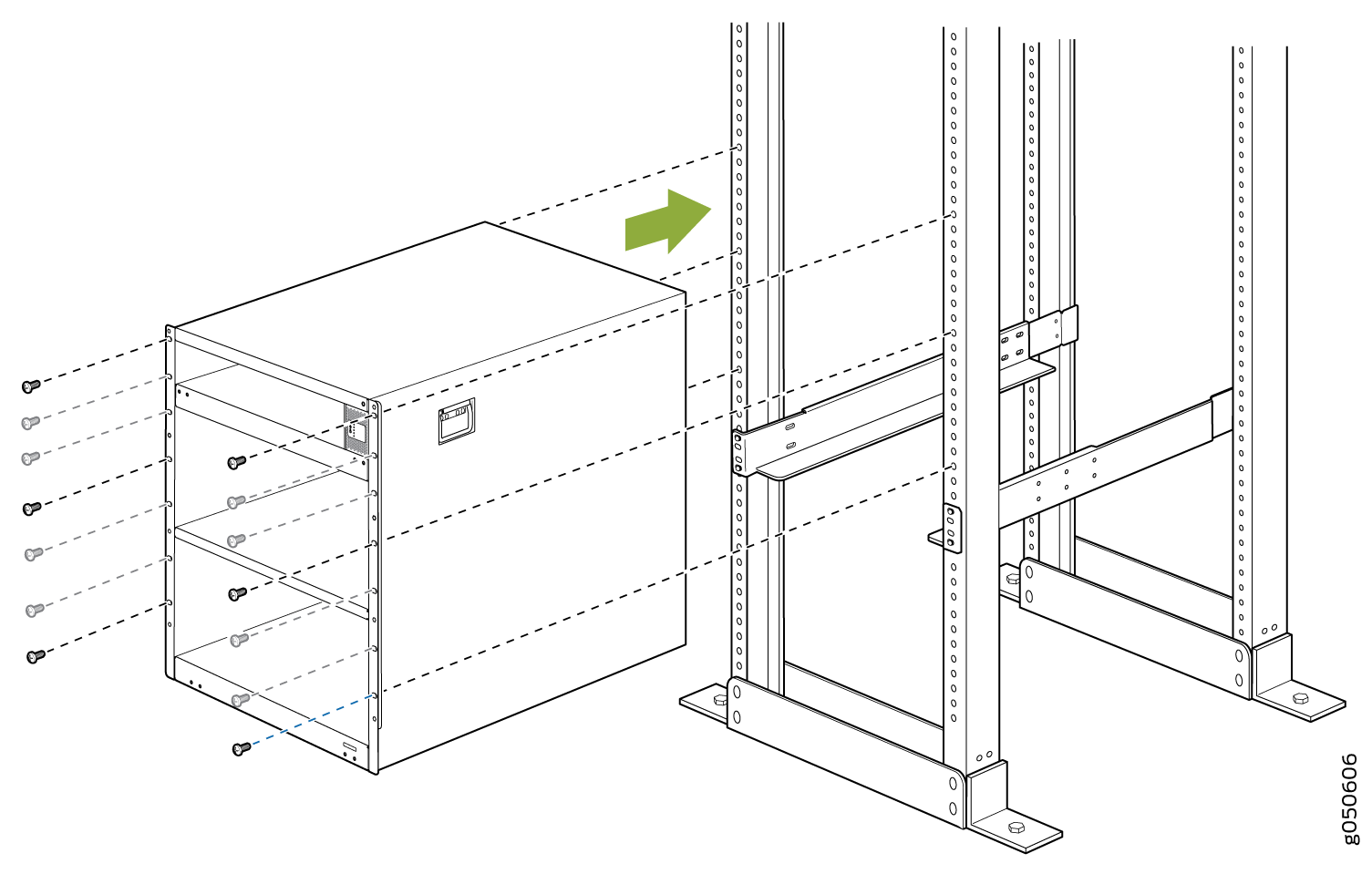
- Carefully slide the chassis onto the adjustable base and
rear mounting brackets until the chassis flanges contact the rack
rails. The mounting brackets ensure that the holes in the flanges
align with the holes in the rack rails. See Figure 2.Figure 2: Attaching the Chassis Flanges to the Rack
See Also
Manually Mounting a QFX10008 in a 4-Post Rack
Before you install the switch:
Prepare the site for installation as described in QFX10008 Site Preparation Checklist.
Ensure the site has adequate clearance for both airflow and hardware maintenance as described in QFX10000 Clearance Requirements for Airflow and Hardware Maintenance.
Unpack the switch as described in Unpacking the Chassis.
Remove all components except the two fan tray controllers from the chassis. See:
Install the mounting hardware at the desired position (see Installing the Mounting Hardware for a QFX10000).
Review chassis lifting guidelines as described in Chassis and Component Lifting Guidelines.
Ensure that you have the following parts and tools available to install the switch:
14 mounting screws appropriate for your rack
A Phillips (+) screwdriver, number 2 or number 3, depending on the size of your rack screws
If you cannot use a mechanical lift to install the switch (the preferred method), you can install it manually.
The chassis weighs approximately 145 lb (66 kg) with only the fan tray controllers installed. Lifting the chassis and mounting it in a rack or cabinet requires at least three people. Make sure the chassis is empty (contains only the backplane) before you lift it.
The chassis has two handles that are designed for subtle positioning of the chassis. Do not lift the chassis by the handles.
Before front-mounting the switch in a rack, have a qualified technician verify that the rack is strong enough to support the switch's weight and is adequately supported at the installation site.
To install the switch in the rack or cabinet (see Figure 4):
If you are installing more than one switch in a rack or cabinet, install the first one at the bottom of the rack. Do not attempt to install a switch manually in an upper position in a rack or cabinet.
- With one person on each side and one person in the rear,
hold the bottom of the chassis and carefully lift it onto the adjustable
base and rear brackets installed in a four-post rack. See Figure 3.Warning:
To prevent injury, keep your back straight and lift with your legs, not your back. Do not twist your body as you lift. Balance the load evenly and be sure that your footing is firm.
Figure 3: Lifting the QFX10008 Without Using a Mechanical Lift
After you install the mounting screws and securely bolt the chassis to the rack, reinstall the components in the chassis. See: