CTP151 Multiservice Interface Module
The Juniper Networks CTP151 Circuit to Packet platform optionally includes a Serial Multiservice Interface module CTP150-IM-SER-MS or CTP150-IM-SER-MS-B. The module provides 4-KHz or high-quality analog audio, or interrange instrumentation group (IRIG) signals.
Starting CTPOS Release 9.1R5, a new serial multiservice interface module (CTP150-IM-SER-MS-B) is introduced. The new CTP150-IM-SER-MS-B is compatible with only CTPOS 9.1R5 and later releases.
The multiservice card enables an IRIG time code (IRIG-B) signal to be transported through an IP network. The IRIG-B standard consists of a family of rate-scaled serial time codes with formats containing up to three coded expressions or words. The IRIG-B pulse code contains one frame of 100 elements per second for the time of the year and GPS receiver status. IRIG-B encodes day of year, hour, minute, and second data on a 1-KHz carrier frequency, with an update rate of once per second.
Only ports 0 and 2 (the bottom two ports) on the front of the serial module can be used for the multiservice features. You can configure direction, output high and low levels, and data range for this module.
The four-port serial interface module supports individual cabling for each port. The CTP151 ports have small serial ports for HD-26 26-pin connectors (see Figure 1). The lowest-numbered port (marked 0) is at the bottom left, and the highest-numbered port (marked 3) is at the top right.
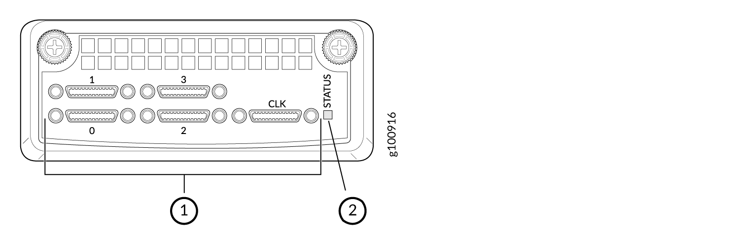
1 — Four small serial ports and one clock reference port | 2 — STATUS LED |
The software-selectable interfaces for the module on all ports are RS-232/V.24, EIA530/X.21, EIA530A, and V.35. Software-selectable rates range from 50 bps to 12.228 Mbps. On ports 0 and 2 there are also options for 64Khz (4WTO) analog, high-quality analog, or IRIG.
The module also includes an external clock reference port (CLK) for an HD-26 connector. Note that only one external clock reference is required even if there are two interface modules, serial or T1/E1.
On the CLK port, differential clock signals are output on the pins 4 and 17 of the HD-26 connector. When an EIA-530A DCE-F serial cable (CTP150-CBL-DB25-DCE-F) is connected to the CLK port, the TT pins 24 and 11 of the DB25 connector output clock signals. If you configure a 32 kHz reference output, an RS-422 32 kHz clock signal is generated on the pins. Even if you disable the 32 kHz reference output and configure an external clock reference, the module expects an RS-422 clock input (of the configured frequency) on the same pins.
The external clock reference port must be used only on the module in slot 0, the left-most slot on the front of the CTP151 chassis. For information about the CTP151 modules slot numbering, see CTP151 Modules Slot and Port Numbering.