CTP151 T1/E1 Interface Module
The Juniper Networks CTP151 Circuit to Packet platform optionally includes a replaceable CTP150-IM-T1E1 or CTP150-IM-T1E1-B interface module that can be paired with another module of the same type or a serial interface module.
Starting CTPOS Release 9.1R5, a new serial multiservice interface module (CTP150-IM-T1E1-B) is introduced. The new CTP150-IM-T1E1-B is compatible with only CTPOS 9.1R5 and later releases.
The four-port T1/E1 interface module supports individual cabling for each port. The CTP151 ports have T1/E1 ports for RJ-48 connectors (see Figure 1). The highest-numbered port (labeled 3) is on the left, and the lowest-numbered port (labeled 0) is at the right, with the CLK port still farther to the right.
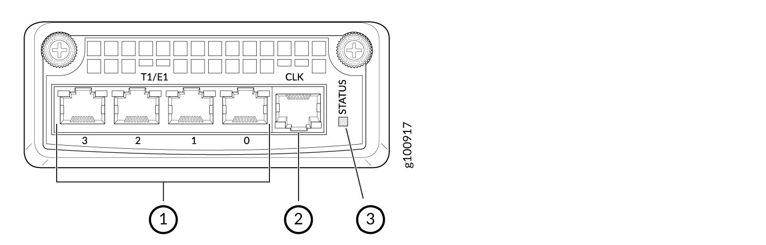
1 — Four T1/E1 ports | 3 — STATUS LED |
2 — One clock reference port |
The software-selectable T1/E1 interfaces for the module are T1, E1, fractional T1, and fractional E1. CSU options, encoding, and encapsulation are also software-selectable.
The module also includes an external clock reference port for an RJ-48 connector.
The external clock reference port must be used only on the module in slot 0, the left-most slot on the front of the CTP151 chassis. For information about the CTP151 modules slot numbering, see CTP151 Modules Slot and Port Numbering.