Help us improve your experience.

Let us know what you think.

Do you have time for a two-minute survey?


Installing a CTP Interface Module, Processor Module, or Clock Module

To install a CTP151 interface module:

  1. Wrap and fasten one end of the ESD grounding strap around your wrist and connect the other end to a site ESD point.
  2. Choose the slot where you want to insert the module. If only a single module is being installed, it must be installed in slot 0.
  3. With a Phillips screwdriver, loosen the screws that secure the blank filler panel covering the empty chassis slot, if present, and remove the filler panel.
  4. Remove the module from its antistatic bag, being careful not to touch module components, pins, leads, or solder connections.
  5. Guide the module into the chassis by placing it between the guides of the selected slot, and gently push the module all the way into the slot.
  6. Seat the module by pushing on the sheet metal tray until the plastic bezel contacts the chassis.
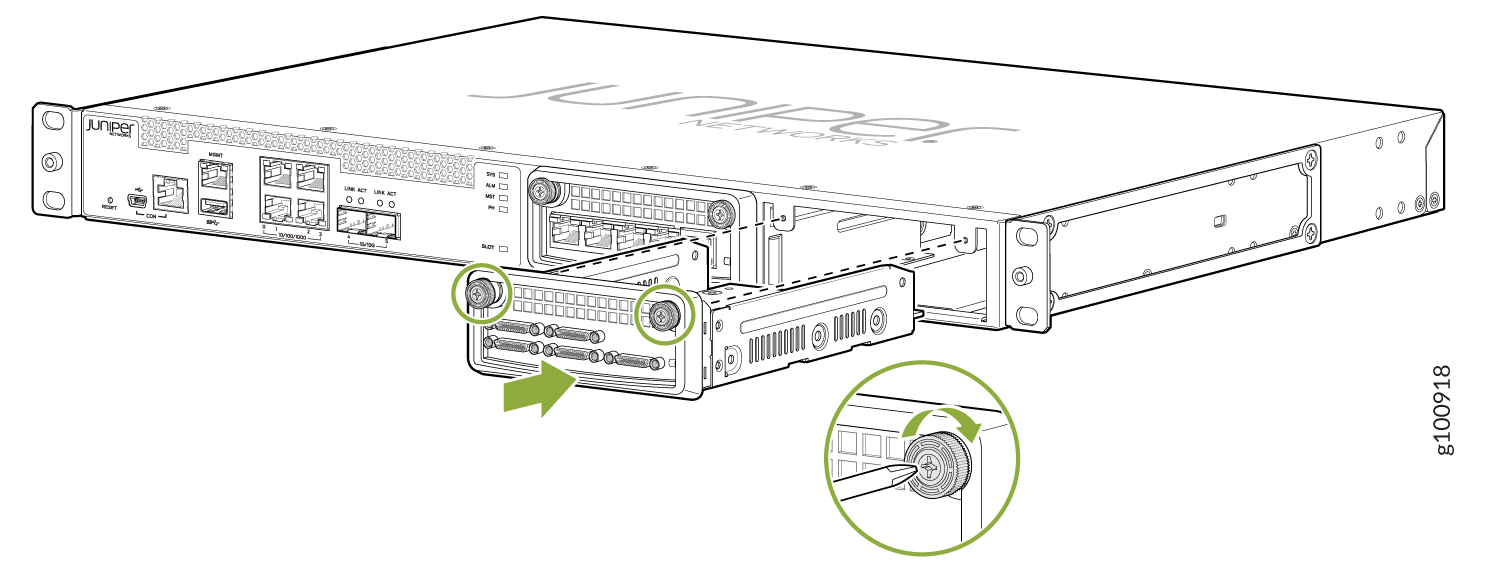
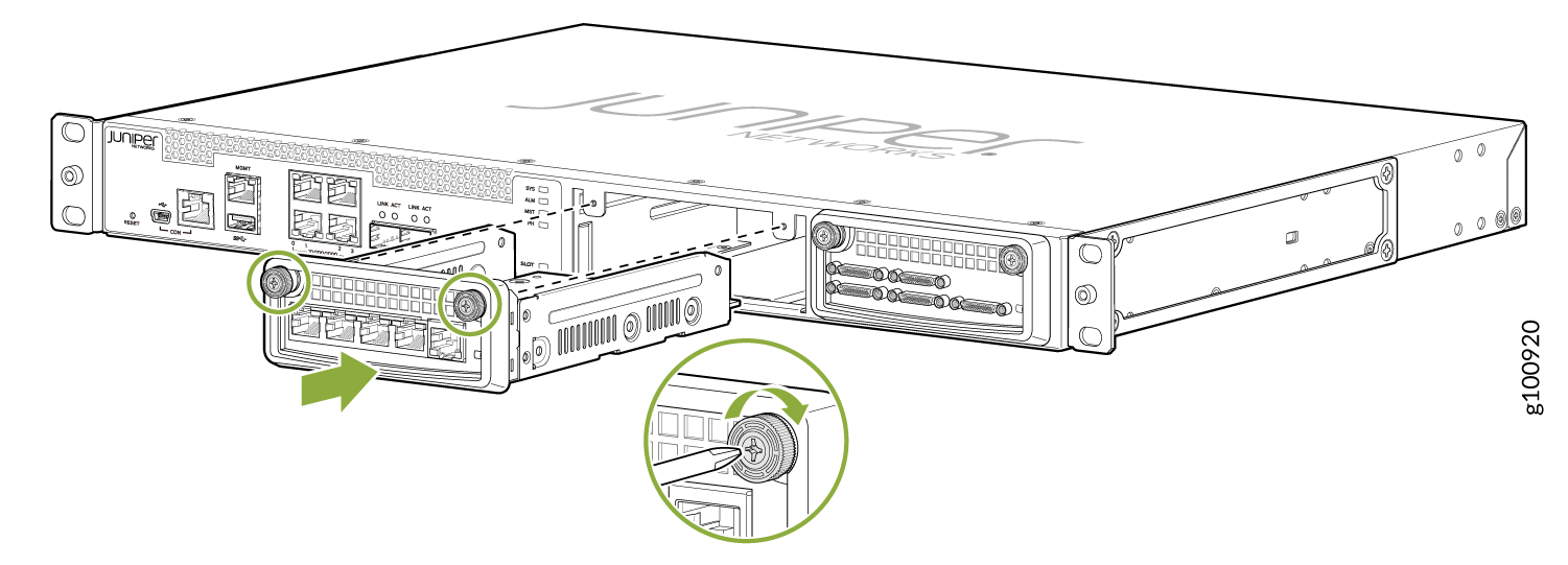
  7. Tighten the module's captive screws using a Phillips screwdriver. See Figure 1.
    Figure 1: Installing Serial and T1/E1 Interface ModulesInstalling Serial and T1/E1 Interface ModulesInstalling Serial and T1/E1 Interface Modules
    Note:

    Tighten the captive screws completely before installing an adjacent module so that proper electromagnetic interference (EMI) gasket compression occurs. Failure to do this can make it difficult to install adjacent modules.