ON THIS PAGE
Installing the MX2008 Mounting Hardware for a Four-Post Rack or Cabinet
Removing Components from the MX2008 Router Chassis Before Installing It in a Rack
Tools Required to Install the MX2008 Router Using a Pallet Jack
Installing the MX2008 Router Using a Pallet Jack with Attachment
Installing an MX2008 Router Using a Router Transport Kit Overview
Tools Required to Install the MX2008 Router Using a Router Transport Kit
Using the Router Transport Kit to Install the Router in a Four-Post Rack
Using the Router Transport Kit to Install the MX2008 Router in an Open-Frame Rack
Reinstalling Components in the MX2008 Router After Initially Installing the Router in a Rack
Installing the MX2008
Installing the MX2008 Mounting Hardware for a Four-Post Rack or Cabinet
- Installing Cage Nuts, If Needed
- Installing the Four-Post Mounting Shelf
- Removing the Center-Mounting Brackets
Installing Cage Nuts, If Needed
Insert cage nuts, if needed, into the holes listed in Table 1 and Table 2. The hole distances are relative to the standard U division on the rack that is aligned with the bottom of the mounting shelf.
To install cage nuts in a four-post rack:
- On the rear side of both rack rails, insert cage nuts in the holes specified for the four-post mounting shelf. Install the cage nuts in the front of the front rail (see Table 1).
- On the front side of both rack rails, insert cage nuts in the holes specified for mounting the chassis. Install the cage nuts in the front of the front rail (see Table 1).
Hole |
Distance Above U Division |
|
|---|---|---|
6 |
3.25 in. (8.3 cm) |
1.86 U |
5 |
2.63 in. (6.7 cm) |
1.5 U |
4 |
2.00 in. (5.1 cm) |
1.14 U |
3 |
1.50 in. (3.8 cm) |
0.86 U |
2 |
0.88 in. (2.2 cm) |
0.50 U |
1 |
0.25 in. (0.6 cm) |
0.14 U |
Hole |
Distance Above U Division |
|
|---|---|---|
110 |
63.88 in. (162.2 cm) |
36.50 U |
101 |
58.63 in. (148.9 cm) |
33.50 U |
92 |
53.38 in. (135.6 cm) |
30.50 U |
83 |
48.13 in. (122.2 cm) |
27.50 U |
74 |
42.88 in. (108.9 cm) |
24.50 U |
65 |
37.63 in. (95.6 cm) |
21.50 U |
56 |
32.38 in. (82.2 cm) |
18.50 U |
47 |
27.13 in. (68.9 cm) |
15.50 U |
38 |
21.88 in. (55.6 cm) |
12.50 U |
29 |
16.63 in. (42.2 cm) |
9.50 U |
20 |
11.38 in. (28.9 cm) |
6.50 U |
11 |
6.13 in. (15.6 cm) |
3.50 U |
The holes in the front-mounting flanges are spaced at 3 U (5.25 in. (13.3 cm)).
Installing the Four-Post Mounting Shelf
A mounting shelf is required for installing the router in a four-post rack or cabinet. The shelf is not required for installing the router in an open-frame rack.
To install the four-post mounting shelf (see Figure 1):
See Also
Removing the Center-Mounting Brackets
The center-mounting brackets are not used for a four-post rack, and must be removed from the chassis.
To remove the center-mounting brackets from the chassis:
Removing Components from the MX2008 Router Chassis Before Installing It in a Rack
Before installing the router with a pallet jack, you must first remove shipping covers and components from the chassis. With components removed, the chassis weighs approximately 324 lb (146.96 kg).
The shipping covers help guide the chassis into the rack. Applying force to any other part of the chassis can cause damage.
- Removing the Power Distribution Modules Before Installing an MX2000 Router with a Pallet Jack
- Removing the Power Supply Modules Before Installing an MX2000 Router
- Removing the Fan Trays Before Installing an MX2010 Router with a Pallet Jack
- Removing the SFBs Before Installing an MX2010 Router with a Pallet Jack
- Removing the MPCs with Adapter Card Before Installing an MX2010 Router with a Pallet Jack
- Removing the MPCs without an Adapter Card Before Installing an MX2010 Router with a Pallet Jack
- Removing the CB-REs Before Installing the MX2010 Router with a Pallet Jack
Removing the Power Distribution Modules Before Installing an MX2000 Router with a Pallet Jack
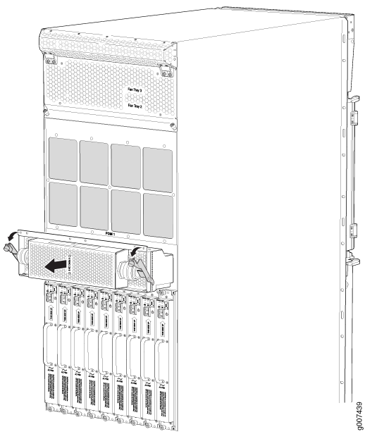
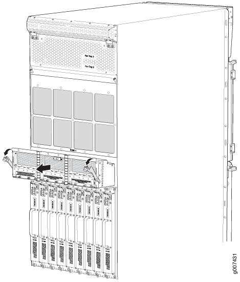
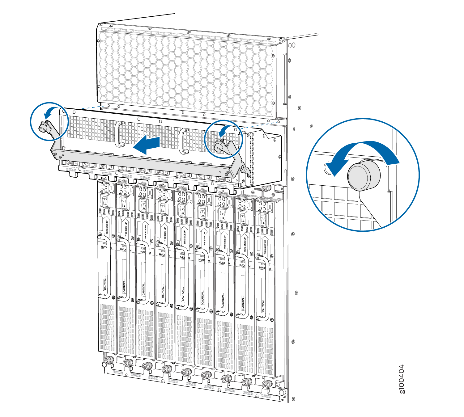
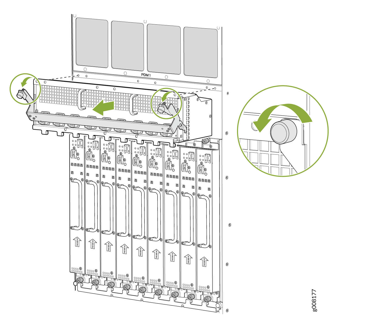
Remove the topmost PDM (PDM1) first, and then work your way downward. To remove an AC, DC, 240 V China, or universal (HVAC/HVDC) PDM (see Figure 3, Figure 4 Figure 5, and Figure 6).
See Also
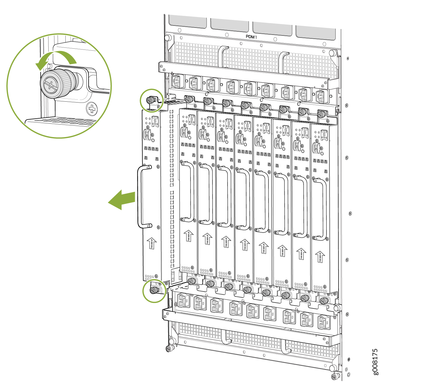
Removing the Power Supply Modules Before Installing an MX2000 Router
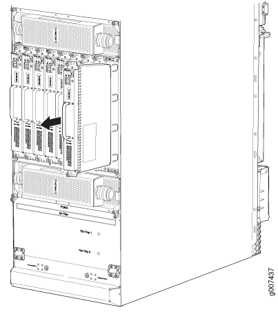
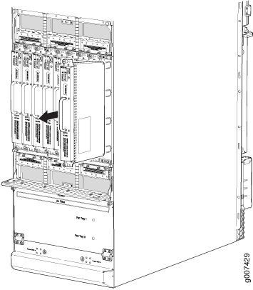
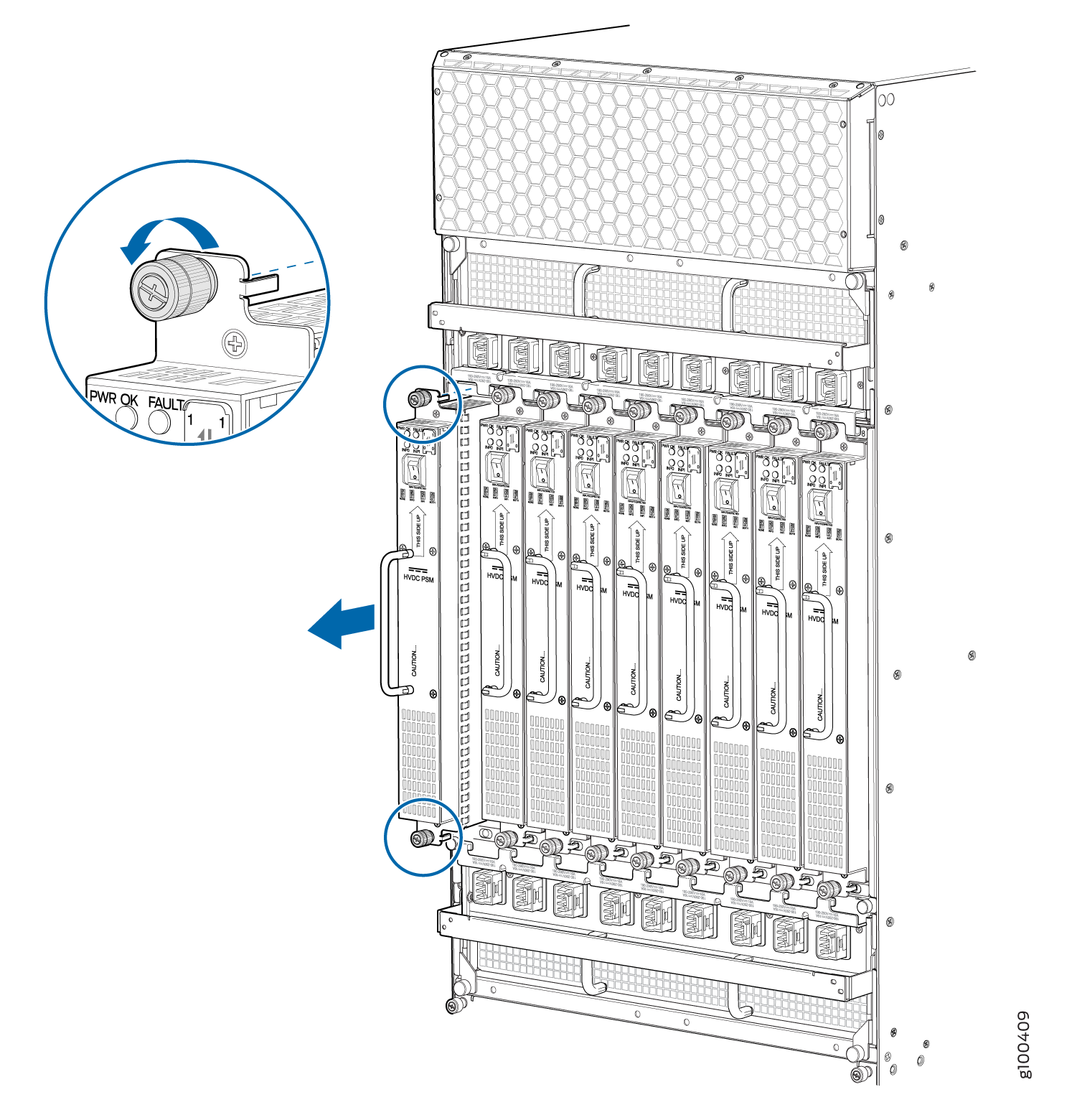
To remove the AC, DC, 240 V China, universal (HVAC/HVDC) PSMs (see Figure 7, Figure 8, Figure 9, and Figure 10):
See Also
Removing the Fan Trays Before Installing an MX2010 Router with a Pallet Jack
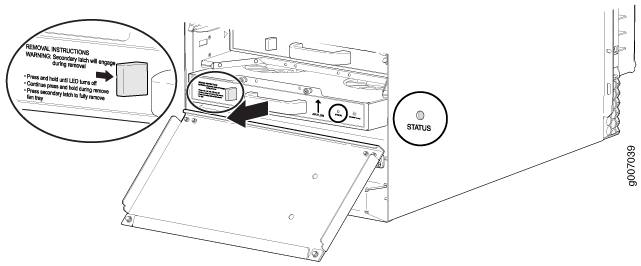
To remove the upper and lower fan tray (see Figure 11 and Figure 12):
The fan trays are interchangeable and are hot-insertable and hot-removable.
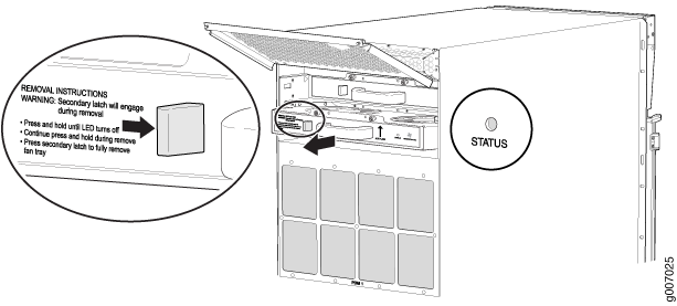
Before removing a fan tray, make sure the fan blades have stopped completely.
See Also
Removing the SFBs Before Installing an MX2010 Router with a Pallet Jack
See Also
Removing the MPCs with Adapter Card Before Installing an MX2010 Router with a Pallet Jack
To remove an MPC with an adapter card (ADC):
See Also
Removing the MPCs without an Adapter Card Before Installing an MX2010 Router with a Pallet Jack
See Also
Removing the CB-REs Before Installing the MX2010 Router with a Pallet Jack
See Also
Installing an MX2008 Router Using a Pallet Jack Overview
Gather the tools required to install the router. See:
Tools Required to Install the MX2008 Router Using a Pallet Jack.
Install the pallet jack attachment. See:
Install the MX2008. See:
Installing the MX2008 Router Using a Pallet Jack with Attachment.
See Also
Tools Required to Install the MX2008 Router Using a Pallet Jack
To install the router, you need the following tools and equipment:
Standard pallet jack (not provided)
Pallet jack attachment—MX2000-PLLT-JCK-ADPTR
Front component shipping covers
Rear component shipping covers
Phillips (+) screwdrivers, numbers 1, 2, and 3
9/16-in. or 14-mm open-end or socket wrench to remove bracket bolts from the shipping pallet
ESD wrist strap
Antistatic mat
See Also
Installing the Pallet Jack Attachment
To install the pallet jack attachment to the pallet jack:
Installing the MX2008 Router Using a Pallet Jack with Attachment
Before installing the router, you must remove all components (see Removing Components from the MX2008 Router Chassis Before Installing It in a Rack).
To install the router by using a pallet jack with attachment:
Installing an MX2008 Router Using a Router Transport Kit Overview
Gather the tools required to install the router. See:
Tools Required to Install the MX2008 Router Using a Router Transport Kit
Install the router transport kit. See:
Secure the router to the router transport platform. See:
Install the router using the router transport kit. See either:
Using the Router Transport Kit to Install the MX2008 Router in a Four-Post Rack or Using the Router Transport Kit to Install the MX2008 Router in an Open-Frame Rack
See Also
Tools Required to Install the MX2008 Router Using a Router Transport Kit
To install the router by using a router transport kit, you need the following tools and equipment:
Router transport kit (model number MX2K-TRNSPRT-KIT)
Front component shipping cover
Rear component shipping cover
Phillips (+) screwdrivers, numbers 1, 2, and 3
1/2-in. (12.7 mm) drive ratchet
1/4-in. (6.35 mm) torque-controlled driver or socket wrench to tighten the nuts on the router transport kit
1-1/8-in. (28.57 mm) torque-controlled driver or socket wrench to tighten the router transport kit winch mechanism
9/16-in. or 14-mm open-end or socket wrench with extension to remove bracket bolts from the shipping pallet
Electrostatic discharge wrist strap
Antistatic mat
The router transport kit does not come with the router. You need to purchase the router transport kit from Juniper Networks. Using the router mounting kit for installing the MX2008 is optional.
See Also
Installing the Router Transport Kit
The router transport kit is optional and can be purchased from Juniper Networks.
The router transport kit includes the following components:
-
Router transport platform
-
Router transport left and right mounting plates with adjustable wheel assembly
-
Router winch mount with winch strap plate
To install the router transport kit:
Securing the Router to the Router Transport Platform
To secure the router to the router transport platform:
Using the Router Transport Kit to Install the Router in a Four-Post Rack
Because of the router's size and weight—up to 985 lb (446.79 kg) depending on the configuration—we recommend that you use a router transport kit to install the router. The router transport kit does not come with the router. You need to purchase the router transport kit from Juniper Networks. Using the router mounting kit for installing the MX2008 is optional.
Four people are needed to install the router into a rack.
Before front mounting the router in a rack, have a qualified technician verify that the rack is strong enough to support the router's weight and is adequately supported at the installation site.
To install the router in a four-post rack by using the router transport kit:
Using the Router Transport Kit to Install the MX2008 Router in an Open-Frame Rack
Four persons are needed to install the router into a rack.
Before front-mounting the router in a rack, have a qualified technician verify that the rack is strong enough to support the router's weight and is adequately supported at the installation site.
To install the MX2008 in an open-frame rack by using a router transport kit:
See Also
Reinstalling Components in the MX2008 Router After Initially Installing the Router in a Rack
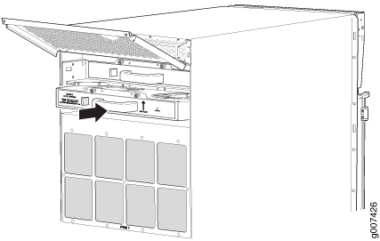
After the router is installed in the rack, remove the shipping covers, and reinstall the removed components before booting and configuring the router. You reinstall components first in the rear of the chassis, and then in the front:
- Reinstalling the Power Distribution Modules After Installing the MX2000 Router with a Pallet Jack
- Reinstalling the Power Supply Modules After Installing the MX2000 Router with a Pallet Jack
- Reinstalling the Fan Trays After Installing the MX2000 Router with a Pallet Jack
- Reinstalling the SFBs After Installing the MX2010 Router with a Pallet Jack
- Reinstalling the Adapter Card After Installing the MX2010 Router with a Pallet Jack
- Reinstalling the MPCs After Installing the MX2010 Router with a Pallet Jack
- Reinstalling the CB-REs After Installing the MX2010 Router with a Pallet Jack
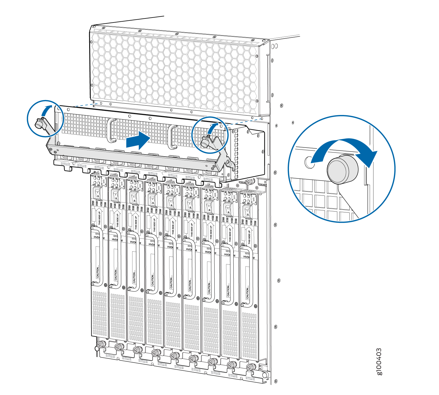
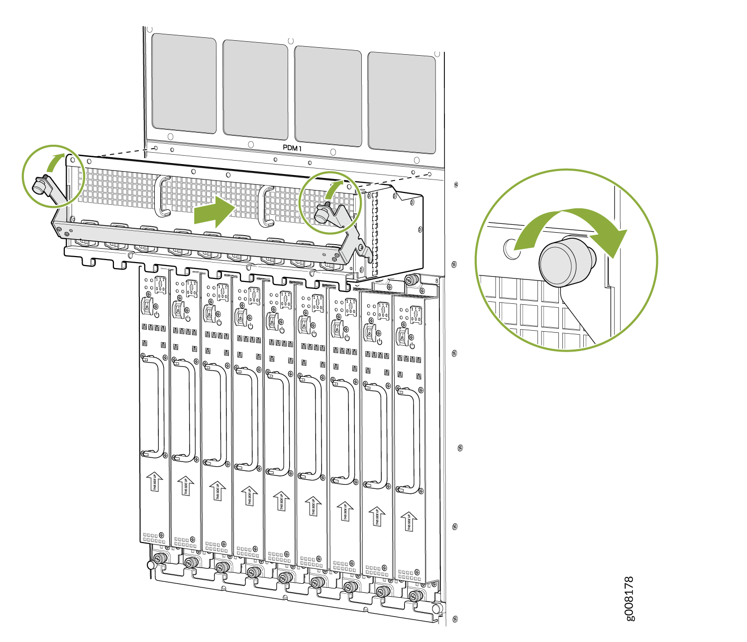
Reinstalling the Power Distribution Modules After Installing the MX2000 Router with a Pallet Jack
To reinstall the AC, DC, 240 V China, or universal PDMs, follow this procedure for each PDM (see Figure 33 and Figure 34):
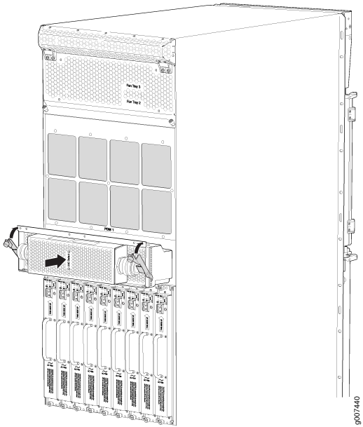
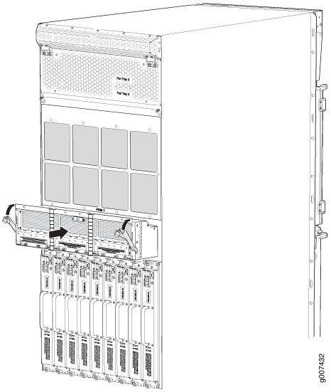
For the DC-powered router, make sure the switch is set to 60 A, or 80 A to match the DC circuit input feed.
See Also
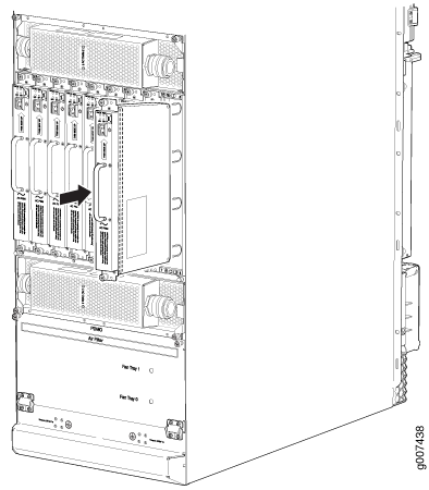
Reinstalling the Power Supply Modules After Installing the MX2000 Router with a Pallet Jack
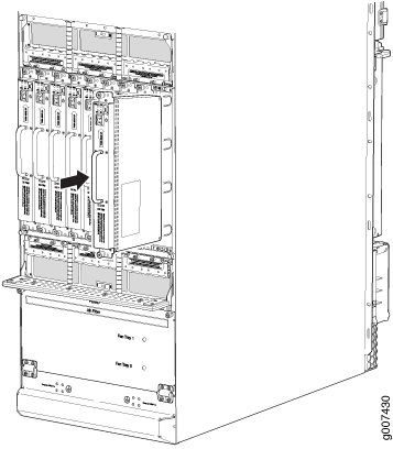
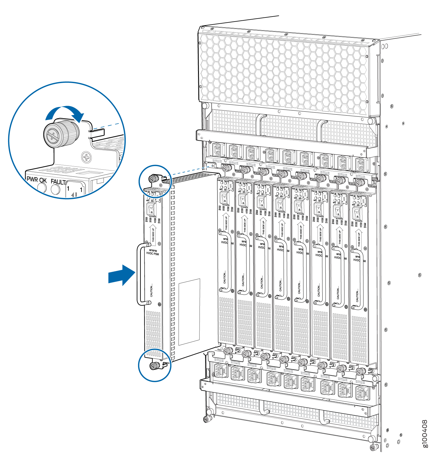
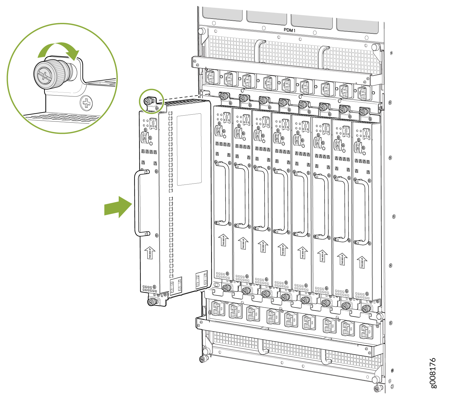
To reinstall the AC, DC, 240 V China, or universal PDMs, follow this procedure for each PSM (see Figure 37 and Figure 38) which shows the installation of the AC or DC PSM.
See Also
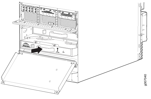
Reinstalling the Fan Trays After Installing the MX2000 Router with a Pallet Jack
See Also
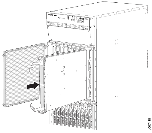
Reinstalling the SFBs After Installing the MX2010 Router with a Pallet Jack
To reinstall an SFB (see Figure 43):
Before removing or replacing an SFB, ensure that the ejector handles are stored horizontally and pressed toward the center of the SFB.
See Also
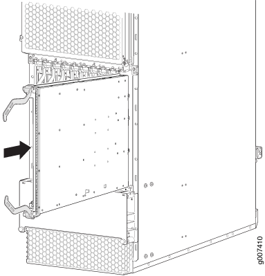
Reinstalling the Adapter Card After Installing the MX2010 Router with a Pallet Jack
To reinstall an ADC (see Figure 44):
- Attach an electrostatic discharge (ESD) grounding strap to your bare wrist, and connect the strap to one of the ESD points on the chassis.
- Take each ADC to be installed out of its electrostatic bag, and identify the slot where it will be installed.
- Locate the slot in the card cage in which you plan to install the ADC.
- Ensure that the ADC is right-side up, with the text on the faceplate facing upward.
- Lift the ADC into place, and carefully align first the bottom, then the top of the ADC with the guides inside the card cage.
- Slide the ADC all the way into the card cage until you feel resistance.
- Grasp both ejector handles, and gently close them inward simultaneously until the ADC is fully seated.
See Also
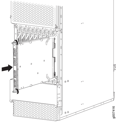
Reinstalling the MPCs After Installing the MX2010 Router with a Pallet Jack
To reinstall an MPC (see Figure 45):
- Attach an electrostatic discharge (ESD) grounding strap to your bare wrist, and connect the strap to one of the ESD points on the chassis.
- Take each MPC to be installed out of its electrostatic bag, and identify the slot where it will be connected.
- Verify that each fiber-optic MPC has a rubber safety cap covering the transceiver. If it does not, cover the transceiver with a safety cap.
- Locate the slot in the ADC in which you plan to install the MPC.
- Ensure that the MPC is right-side up, with the text on the faceplate facing upward.
- Lift the MPC into place, and carefully align first the bottom, then the top of the MPC with the guides inside the ADC.
- Slide the MPC all the way into the ADC until you feel resistance.
- Turn both knobs and rotate them simultaneously clockwise until the MPC is fully seated into the ADC.
See Also
Reinstalling the CB-REs After Installing the MX2010 Router with a Pallet Jack
To reinstall a CB-RE (see Figure 46):
- Attach an electrostatic discharge (ESD) grounding strap to your bare wrist, and connect the strap to one of the ESD points on the chassis.
- Take each CB-RE to be installed out of its electrostatic bag, and identify the slot on the CB-RE where it will be connected.
- Verify that each fiber-optic CB-RE has a rubber safety cap covering the transceiver. If it does not, cover the transceiver with a safety cap.
- Locate the slot in the CB-RE card cage in which you plan to install the CB-RE.
- Ensure that the CB-RE is right-side up, with the text on the faceplate of the CB-RE facing upward.
- Lift the CB-RE into place, and carefully align first the bottom, then the top of the CB-RE with the guides inside the card cage.
- Slide the CB-RE all the way into the card cage until you feel resistance.
- Grasp both ejector handles, and gently close them inward simultaneously until the CB-RE is fully seated.
