PTX10016 Chassis
The PTX10016 chassis houses the hardware components. The chassis components include the fan trays, fan tray controllers, power supplies, Routing and Control Boards (RCBs), line cards, an optional cable management system, and the status panel.
PTX10016 Field-Replaceable Units
Field-replaceable units (FRUs) are router components that you can replace at your site. The router uses the following types of FRUs:
Hot-insertable and hot-removable—You can remove and replace these components without powering off the router or disrupting the routing function.
Hot-pluggable—You can remove and replace these components without powering off the router, but the routing function is interrupted until you replace the component.
Table 1 lists the FRUs and their types for the PTX10016 routers.
FRU |
Type |
|---|---|
Power supplies |
Hot-insertable and hot-removable. |
Fan trays |
Hot-insertable and hot-removable. |
Fan tray controllers |
Hot-insertable and hot-removable. |
RCBs |
Redundant configuration:
Base configuration:
|
Switch Interface Boards (SIBs) |
Hot-insertable and hot-removable. We recommend that you take the SIBs offline before removing them to avoid traffic loss while you reconfigure the router fabric. Use the following command: user@router> request chassis sib slot slot-number offline |
Line cards |
Hot-insertable. We recommend that you take line cards offline before removing them. Use the following command: user@router> request chassis fpc slot slot-number offline |
Optical transceivers See PTX10016 Optical Transceiver and Cable Support for how to find detailed specifications and the Junos OS release in which the transceivers were introduced. |
Hot-insertable and hot-removable. |
Line cards are not part of the base or redundant configuration. You must order them separately.
If you have a Juniper® Care Services service contract, register any addition, change, or upgrade of hardware components at https://www.juniper.net/customers/support/tools/updateinstallbase/. Failure to do so can result in significant delays if you need replacement parts. This note does not apply if you replace an existing component with the same type of component.
PTX10016 Status Panel
The status panel of the PTX10016 has two purposes:
Shows the overall status of the chassis
Indicates the type of power bus internal to the chassis
Some chassis ship with an enhanced power bus that future-proofs the chassis for potential power growth.
The status panel indicates the chassis status through a set of five bicolor LEDs. See Figure 1 for a chassis status panel with the standard power bus.
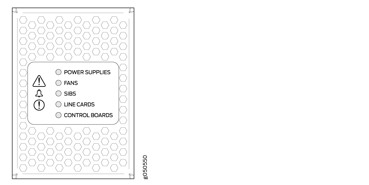
Other chassis also have the same set of five bicolor LEDs, but also have an azure blue line to indicate the presence of the enhanced power bus (see Figure 2).
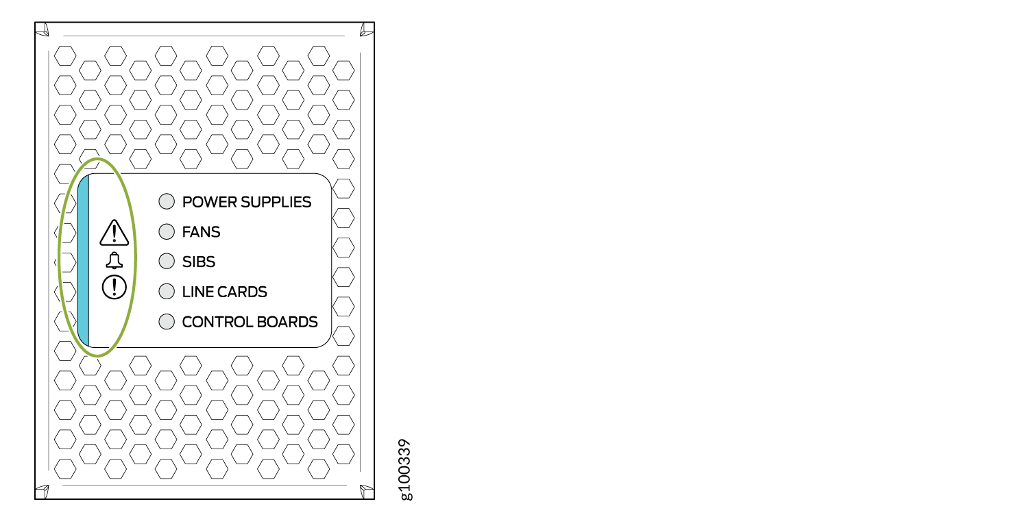
Table 2 describes the status panel LEDs.
Name |
Color |
State |
Description |
|---|---|---|---|
! Minor alarm (Triangle warning symbol) |
Yellow |
Off |
No minor alarms are active. |
On steadily |
A minor alarm is active. |
||
! Major alarm (Circle warning symbol) |
Red |
Off |
No major alarms are active. |
On steadily |
A major alarm is active. |
||
|
POWER SUPPLIES |
Green |
On steadily |
All of the power supplies are online and operating normally. |
Yellow |
On steadily (if Junos OS Evolved is installed in your router)/Blinking (if Junos OS is installed in your router) |
One or more of the power supplies has an error. |
|
None |
Off |
None of the power supplies is receiving power. |
|
FANS |
Green |
On steadily |
The fans and the fan tray controllers are online and operating normally. |
Yellow |
Blinking |
There is an error in a fan or in one of the fan tray controllers. |
|
None |
Off |
The fan tray controllers and fan trays are not receiving power. |
|
SIBS |
Green |
On steadily |
At least one installed SIB is online. |
Yellow |
Blinking |
There is a hardware error in one or more SIBs. |
|
None |
Off |
All the SIBs are offline. |
|
LINE CARDS |
Green |
On steadily |
At least one installed line card is online. |
Yellow |
Blinking |
There is a hardware error in one or more line cards. |
|
None |
Off |
All the line cards are offline. |
|
CONTROL BOARDS |
Green |
On steadily |
All installed RCBs are online. |
Yellow |
Blinking |
One or more RCBs have an error condition. |
|
None |
Off |
The installed RCBs are offline. |
See Also
PTX10016 Optional Equipment
The PTX10016 router supports the cable management system as optional equipment.
PTX10016 Cable Management System
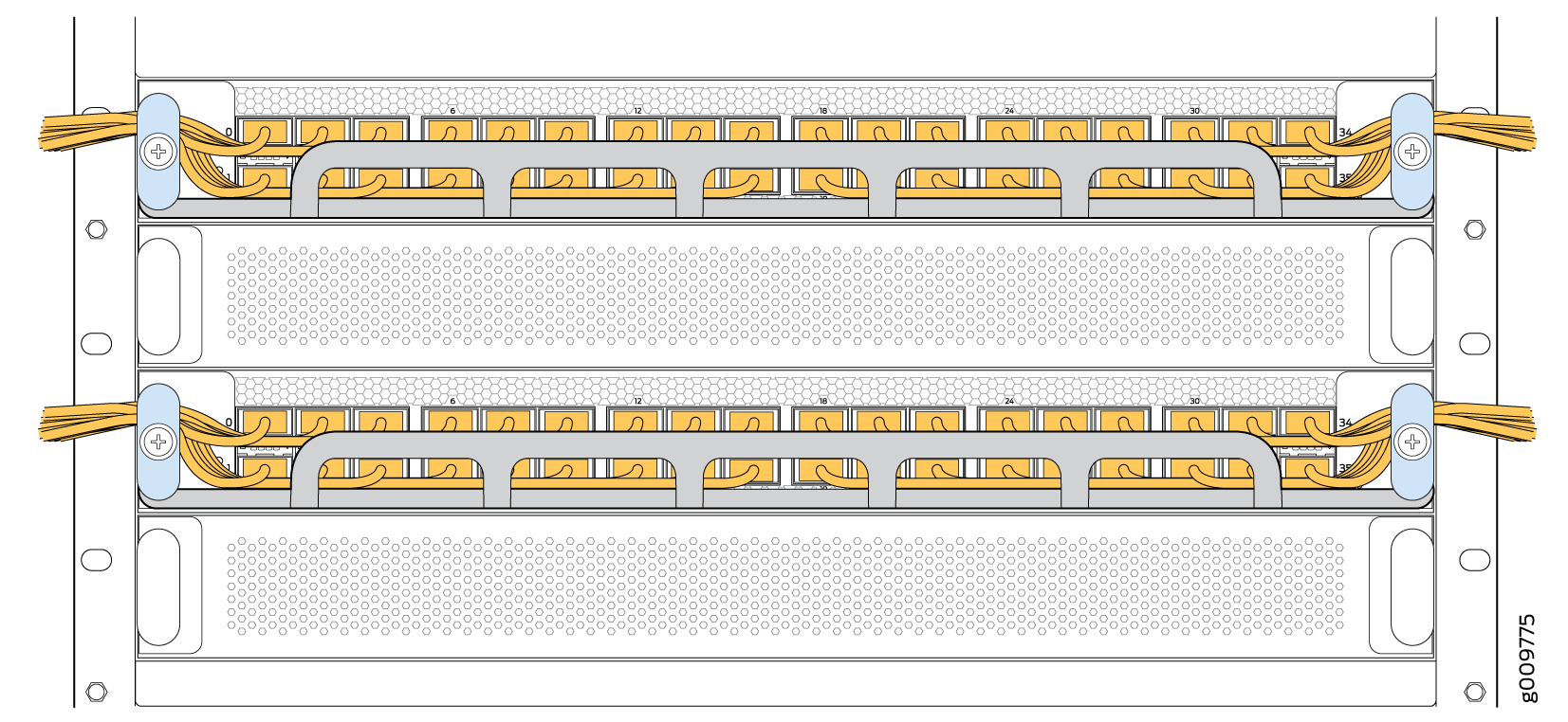
You can use the PTX10016 cable management system (see Figure 3) to route optical cables away from the line card ports for better airflow through the chassis. Using this optional system also makes it easier to use cable ties or strips to organize the cabling.
The cable management system (part number: JLC-CBL-MGMT-KIT) is a spare part and is not shipped by default. You must order it separately.
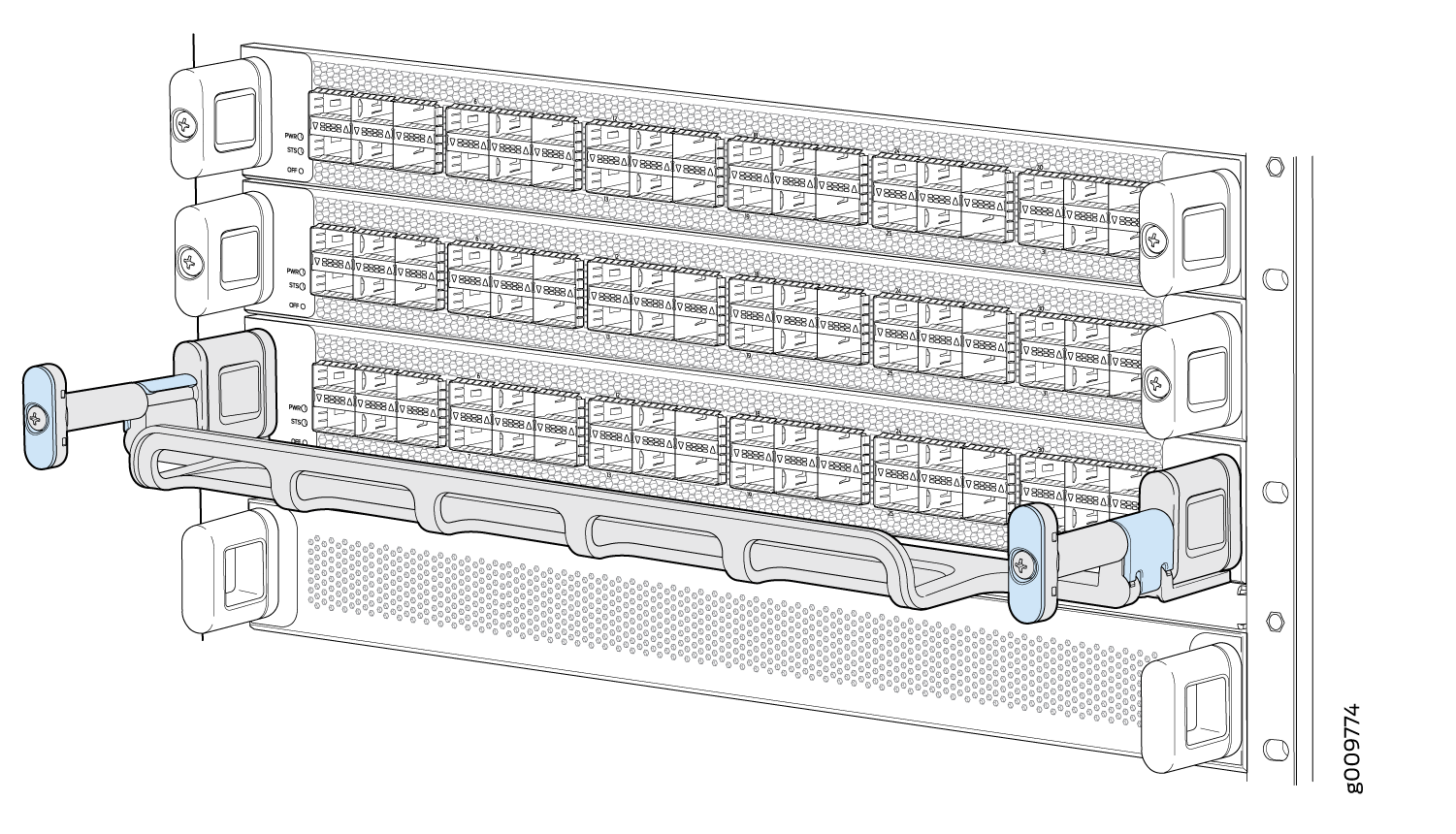
The cable management system comprises a set of handle extensions and a tray that snaps to the extensions (see Figure 4) for an individual line card. You can use the handle extensions with or without the cable tray. You need not remove the handle extensions if you want to remove a line card.
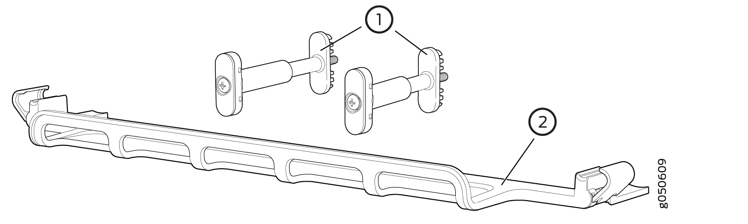
1 — Handle extensions | 2 — Cable tray |
Cables are draped across or under the handle extensions and then secured with cable wraps (see Figure 5).