Configuring Multicast VLAN Registration on EX Series Switches
Multicast VLAN registration (MVR) enables hosts that are not part of a multicast VLAN (MVLAN) to receive multicast streams from the MVLAN, sharing the MVLAN across multiple VLANs in a Layer 2 network. Hosts remain in their own VLANs for bandwidth and security reasons but are able to receive multicast streams on the MVLAN.
MVR is not enabled by default on switches that support MVR. You must explicitly configure a switch with a data-forwarding source MVLAN and associate it with one or more data-forwarding MVR receiver VLANs. When you configure one or more VLANs on a switch to be MVR receiver VLANs, you must configure at least one associated source MVLAN. However, you can configure a source MVLAN without associating MVR receiver VLANs with it at the same time.
The overall purpose and benefits of employing MVR are the same on switches that use Enhanced Layer 2 Software (ELS) configuration style and those that do not use ELS. However, there are differences in MVR configuration and operation on the two types of switches.
Configuring Multicast VLAN Registration on EX Series Switches with ELS
The following are configuration frameworks we recommended for MVR to operate smoothly on EX Series switches that support Enhanced Layer 2 Software (ELS) configuration style in single-tier or multiple-tier access layers:
In an access layer with a single tier of switches, where a switch is connected to a multicast router in the upstream direction, and has host trunk or access ports connecting to downstream multicast receivers:
Configure MVR on the receiver VLANs to operate in proxy mode.
Statically configure the upstream interface to the multicast router as a multicast router port in the MVLAN.
Configure the
translateoption on MVR receiver VLANs that have trunk ports, so hosts on those trunk ports receive the multicast packets tagged for their own VLANs.
In an access layer with multiple tiers of switches, with a switch connected upstream to the multicast router and a path through one or more downstream switches to multicast receivers:
Configure MVR on the receiver VLANs to operate in proxy mode on the uppermost switch that is directly connected to the upstream multicast router.
Configure MVR on the receiver VLANs to operate in transparent mode for the remaining downstream tiers of switches.
Statically configure a multicast router port to the switch in the upstream direction on each tier for the MVLAN.
On the lowest tier of MVR switches (connected to receiver hosts), configure MVLAN tag translation for MVR receiver VLANs that have trunk ports, so hosts on those trunk ports receive the multicast stream with the packets tagged with their own VLANs.
When enabling MVR on ELS switches, depending on your multicast network requirements, you can have some MVR receiver VLANs configured in proxy mode and some in transparent mode that are associated with the same MVLAN, because the MVR mode setting applies individually to an MVR receiver VLAN. The mode configurations described here are only recommendations for smooth MVR operation in those topologies.
The following constraints apply when configuring MVR on ELS EX Series switches:
MVR is supported on VLANs running IGMP version 2 (IGMPv2) only.
You can configure up to 10 MVLANs on an EX4300 or EX4300 multigigabit switch, up to 5 MVLANs on EX2300 and EX3400 switches, and up to a total of 4K MVR receiver VLANs and MVLANs together.
A VLAN can be configured as either an MVLAN or an MVR receiver VLAN, not both. However, an MVR receiver VLAN can be associated with more than one MVLAN.
An MVLAN can be the source for only one multicast group subnet, so multiple MVLANs configured on a switch must have unique multicast group subnet ranges.
You can configure an interface in both an MVR receiver VLAN and its MVLAN only if it is configured as a multicast router port in both VLANs.
You cannot configure proxy mode with the
installoption to also install forwarding entries on an MVR receiver VLAN. In proxy mode, IGMP reports are sent to the upstream router only in the context of the MVLAN. Multicast sources will not receive IGMP reports on the MVR receiver VLAN , and multicast traffic will not be sent on the MVR receiver VLAN.MVR does not support configuring an MVLAN or MVR receiver VLANs on private VLANs (PVLANs).
To configure MVR on ELS EX Series switches that support MVR:
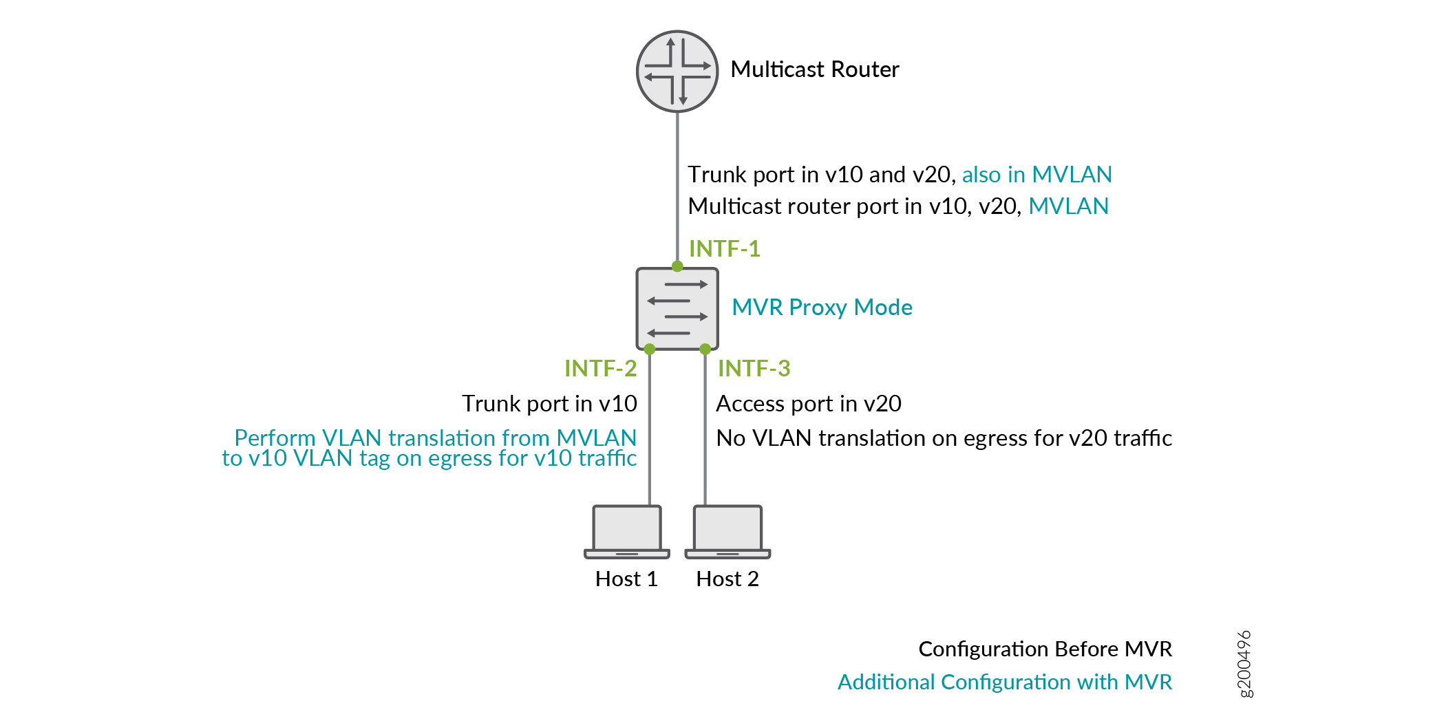
Figure 1 illustrates a single-tier access layer topology in which MVR is employed with an MVLAN named mvlan and receiver hosts on MVR receiver VLANs v10 and v20. A sample of the recommended MVR configuration for this topology follows the figure.

The MVR switch in Figure 1 is configured in proxy mode, connects to the upstream multicast router on interface INTF-1, and connects to receiver hosts on v10 using trunk port INTF-2 and on v20 using access port INTF-3. The switch is configured to translate MVLAN tags in the multicast stream into the receiver VLAN tags only for v10 on INTF-2.
# Receiver VLAN configuration before configuring MVR
set interfaces INTF-1 unit 0 family ethernet-switching vlan members v10
set interfaces INTF-1 unit 0 family ethernet-switching vlan members v20
set interfaces INTF-1 unit 0 family ethernet-switching interface-mode trunk

set interfaces INTF-2 unit 0 family ethernet-switching vlan members v10
set interfaces INTF-2 unit 0 family ethernet-switching interface-mode trunk
set interfaces INTF-3 unit 0 family ethernet-switching vlan members v20

set vlans v10 vlan-id 10

set vlans v20 vlan-id 20


set protocols igmp-snooping vlan v10
set protocols igmp-snooping vlan v10 interface INTF-1 multicast-router-interface
set protocols igmp-snooping vlan v20
set protocols igmp-snooping vlan v20 interface INTF-1 multicast-router-interface

# Additional configuration for MVR
set interfaces INTF-1 unit 0 family ethernet-switching vlan members mvlan
set vlans mvlan vlan-id 100
set protocols igmp-snooping vlan mvlan data-forwarding source groups 233.252.0.0/8
set protocols igmp-snooping vlan mvlan interface INTF-1 multicast-router-interface

set protocols igmp-snooping vlan v10 data-forwarding receiver source-list mvlan
set protocols igmp-snooping vlan v10 data-forwarding receiver mode proxy
set protocols igmp-snooping vlan v10 data-forwarding receiver translate

set protocols igmp-snooping vlan v20 data-forwarding receiver source-list mvlan
set protocols igmp-snooping vlan v20 data-forwarding receiver mode proxy
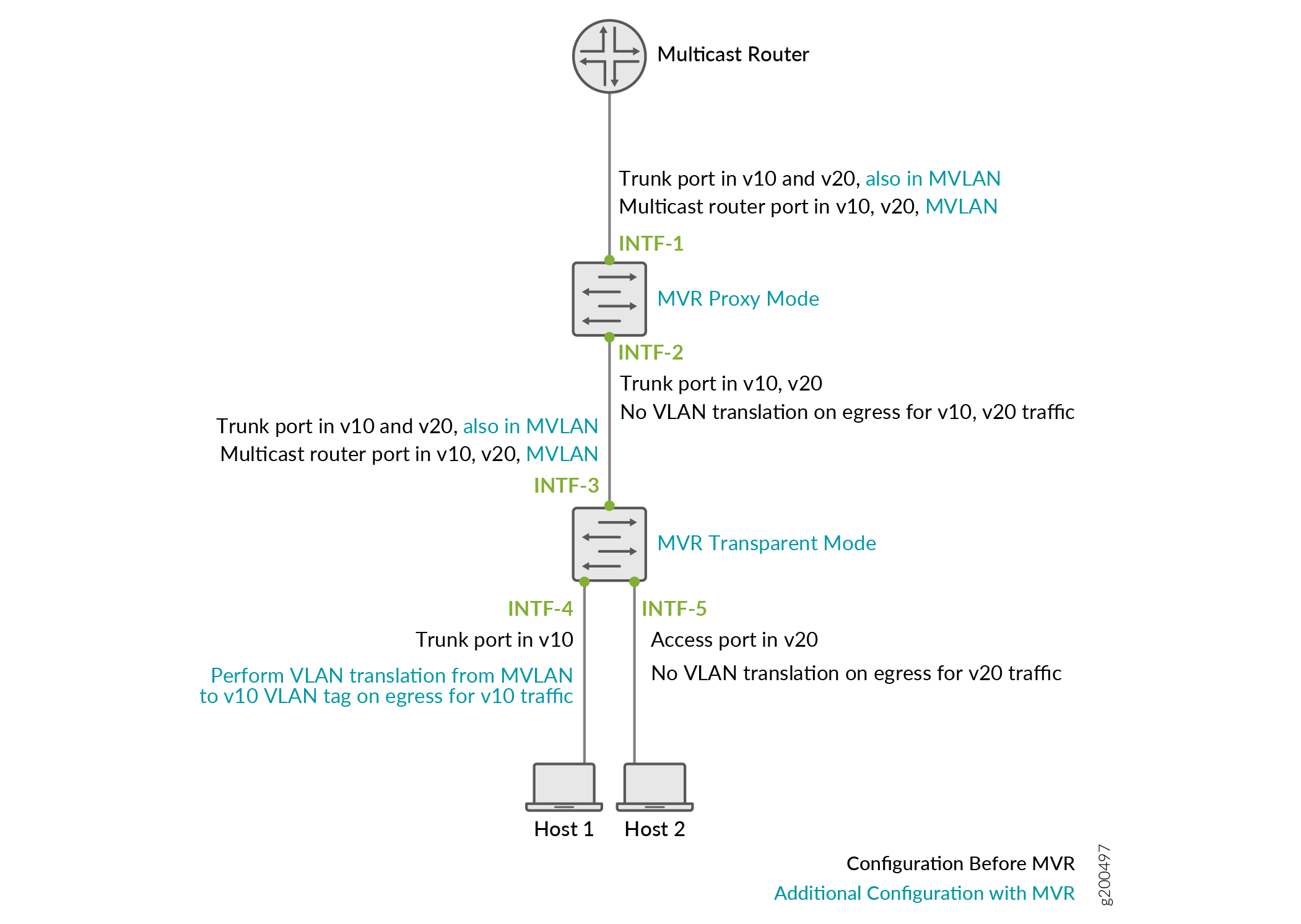
Figure 2 illustrates a two-tier access layer topology in which MVR is employed with an MVLAN named mvlan, MVR receiver VLANs v10 and v20, and receiver hosts connected to trunk port INTF-4 on v10 and access port INTF-5 on v20. A sample of the recommended MVR configuration for this topology follows the figure.

The upper switch in Figure 2 connects to the upstream multicast router on INTF-1, and the lower switch connects to the upper switch on INTF-3, both configured as trunk ports and multicast router interfaces in the MVLAN. The upper switch is configured in proxy mode and the lower switch is configured in transparent mode for all MVR receiver VLANs. The lower switch is configured to translate MVLAN tags in the multicast stream into the receiver VLAN tags for v10 on INTF-4.
Upper Switch:
# Receiver VLAN configuration before configuring MVR
set interfaces INTF-1 unit 0 family ethernet-switching vlan members v10
set interfaces INTF-1 unit 0 family ethernet-switching vlan members v20
set interfaces INTF-1 unit 0 family ethernet-switching interface-mode trunk

set interfaces INTF-2 unit 0 family ethernet-switching vlan members v10
set interfaces INTF-2 unit 0 family ethernet-switching vlan members v20
set interfaces INTF-2 unit 0 family ethernet-switching interface-mode trunk

set vlans v10 vlan-id 10

set vlans v20 vlan-id 20


set protocols igmp-snooping vlan v10
set protocols igmp-snooping vlan v10 interface INTF-1 multicast-router-interface
set protocols igmp-snooping vlan v20
set protocols igmp-snooping vlan v20 interface INTF-1 multicast-router-interface

# Additional configuration for MVR
set interfaces INTF-1 unit 0 family ethernet-switching vlan members mvlan
set vlans mvlan vlan-id 100
set protocols igmp-snooping vlan mvlan data-forwarding source groups 233.252.0.0/8
set protocols igmp-snooping vlan mvlan interface INTF-1 multicast-router-interface

set protocols igmp-snooping vlan v10 data-forwarding receiver source-list mvlan
set protocols igmp-snooping vlan v10 data-forwarding receiver mode proxy

set protocols igmp-snooping vlan v20 data-forwarding receiver source-list m-vlan
set protocols igmp-snooping vlan v20 data-forwarding receiver mode proxy
Lower Switch:
# Receiver VLAN configuration before configuring MVR
set interfaces INTF-3 unit 0 family ethernet-switching vlan members v10
set interfaces INTF-3 unit 0 family ethernet-switching vlan members v20
set interfaces INTF-3 unit 0 family ethernet-switching interface-mode trunk

set interfaces INTF-4 unit 0 family ethernet-switching vlan members v10
set interfaces INTF-4 unit 0 family ethernet-switching interface-mode trunk

set interfaces INTF-5 unit 0 family ethernet-switching vlan members v20

set vlans v10 vlan-id 10

set vlans v20 vlan-id 20


set protocols igmp-snooping vlan v10
set protocols igmp-snooping vlan v10 interface INTF-3 multicast-router-interface
set protocols igmp-snooping vlan v20
set protocols igmp-snooping vlan v20 interface INTF-3 multicast-router-interface

# Additional configuration for MVR
set interfaces INTF-3 unit 0 family ethernet-switching vlan members mvlan
set protocols igmp-snooping vlan mvlan data-forwarding source groups 233.252.0.0/8
set protocols igmp-snooping vlan mvlan interface INTF-3 multicast-router-interface
set vlans mvlan vlan-id 100

set protocols igmp-snooping vlan v10 data-forwarding receiver source-list mvlan
set protocols igmp-snooping vlan v10 data-forwarding receiver mode transparent
set protocols igmp-snooping vlan v10 data-forwarding receiver translate

set protocols igmp-snooping vlan v20 data-forwarding receiver source-list mvlan
set protocols igmp-snooping vlan v20 data-forwarding receiver mode transparent
Viewing MVLAN and MVR Receiver VLAN Information on EX Series Switches with ELS
On EX Series switches with the Enhanced Layer 2 Software (ELS) configuration style that support MVR, you can use the show igmp snooping data-forwarding command to view information about the MVLANs and MVR receiver VLANs configured on a switch, as follows:
user@host> show igmp snooping data-forwarding
Instance: default-switch

Vlan: v2

Learning-Domain 	: default
Type            	: MVR Source Vlan
Group subnet    	: 225.0.0.0/24
Receiver vlans:
    vlan: v1
    vlan: v3

Vlan: v1

Learning-Domain 	: default
Type            	: MVR Receiver Vlan
Mode            	: PROXY
Egress translate	: FALSE
Install route   	: FALSE
Source vlans:
    vlan: v2

Vlan: v3

Learning-Domain 	: default
Type            	: MVR Receiver Vlan
Mode            	: TRANSPARENT
Egress translate	: FALSE
Install route   	: TRUE
Source vlans:
    vlan: v2
MVLANs are listed as Type: MVR Source Vlan with the associated group subnet range and MVR receiver VLANs. MVR
receiver VLANs are listed as Type: MVR Receiver Vlan with the associated source MVLANs and configured options (proxy
or transparent mode, VLAN tag translation, and installation of receiver
VLAN forwarding entries).
In addition, the show igmp snooping
interface and show igmp snooping
membership commands on ELS EX Series switches list MVR
receiver VLAN interfaces under both the MVR receiver VLAN and its
MVLAN, and display the output field Data-forwarding
receiver: yes when MVR receiver ports are listed under
the MVLAN. This field is not displayed for other interfaces in an
MVLAN listed under the MVLAN that are not in MVR receiver VLANs.
Configuring Multicast VLAN Registration on non-ELS EX Series Switches
When you configure MVR on EX Series switches that do not support Enhanced Layer 2 Software (ELS) configuration style, the following constraints apply:
MVR is supported on VLANs running IGMP version 2 (IGMPv2) only.
A VLAN can be configured as an MVLAN or an MVR receiver VLAN, but not both. However, an MVR receiver VLAN can be associated with more than one MVLAN.
An MVLAN can be the source for only one multicast group subnet, so multiple MVLANs configured on a switch must have disjoint multicast group subnets.
After you configure a VLAN as an MVLAN, that VLAN is no longer available for other uses.
You cannot enable multicast protocols on VLAN interfaces that are members of MVLANs.
If you configure an MVLAN in proxy mode, IGMP snooping proxy mode is automatically enabled on all MVR receiver VLANs of this MVLAN. If a VLAN is an MVR receiver VLAN for multiple MVLANs, all of the MVLANs must have proxy mode enabled or all must have proxy mode disabled. You can enable proxy mode only on VLANs that are configured as MVR source VLANs and that are not configured for Q-in-Q tunneling.
You cannot configure proxy mode with the
installoption to also install forwarding entries for received IGMP packets on an MVR receiver VLAN.
To configure MVR on switches that do not support ELS:
