Multicast Snooping for VPLS
Understanding PIM Snooping for VPLS
There are two ways to direct PIM control packets:
By the use of PIM snooping
By the use of PIM proxying
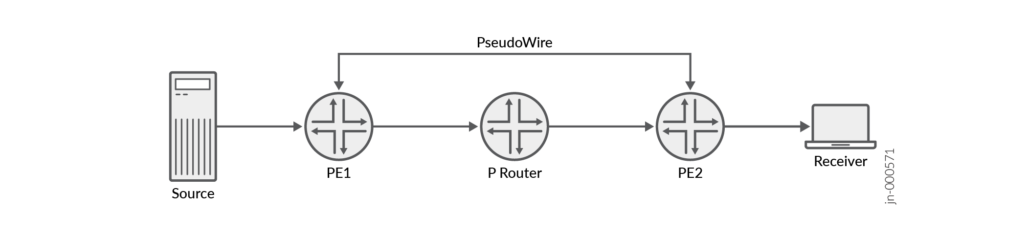
PIM snooping configures a device to examine and operate only on PIM hello and join/prune packets. A PIM snooping device snoops PIM hello and join/prune packets on each interface to find interested multicast receivers and populates the multicast forwarding tree with this information. PIM snooping differs from PIM proxying in that both PIM hello and join/prune packets are transparently flooded in the VPLS as opposed to the flooding of only hello packets in the case of PIM proxying. PIM snooping is configured on PE routers connected through pseudowires. PIM snooping ensures that no new PIM packets are generated in the VPLS, with the exception of PIM messages sent through LDP on pseudowires.
In the VPLS documentation, the word router in terms such as PE router is used to refer to any device that provides routing functions.
A device that supports PIM snooping snoops hello packets received on attachment circuits. It does not introduce latency in the VPLS core when it forwards PIM join/prune packets.
To configure PIM snooping on a PE router, use the pim-snooping statement at the [edit routing-instances instance-name protocols] hierarchy level:
routing-instances {
    customer {
        instance-type vpls;
        ...
        protocols {
            pim-snooping{
                traceoptions {
                    file pim.log size 10m;
                    flag all;
                    flag timer disable;
                }
            }
        }
    }
}
Example: Configuring PIM Snooping for VPLS explains the PIM snooping method. The use of the PIM proxying method is not discussed here and is outside the scope of this document. For more information about PIM proxying, see PIM Snooping over VPLS.
Example: Configuring PIM Snooping for VPLS
This example shows how to configure PIM snooping in a virtual private LAN service (VPLS) to restrict multicast traffic to interested devices.
Requirements
This example uses the following hardware and software components:
M Series Multiservice Edge Routers (M7i and M10i with Enhanced CFEB, M120, and M320 with E3 FPCs) or MX Series 5G Universal Routing Platforms (MX80, MX240, MX480, and MX960)
Junos OS Release 13.2 or later
Overview
The following example shows how to configure PIM snooping to restrict multicast traffic to interested devices in a VPLS.
This example demonstrates PIM snooping by the use of a PIM snooping device to restrict multicast traffic. The use of the PIM proxying method to achieve PIM snooping is out of the scope of this document and is yet to be implemented in Junos OS.
Topology
In this example, two PE routers are connected to each other through a pseudowire connection. Router PE1 is connected to Routers CE1 and CE2. A multicast receiver is attached to Router CE2. Router PE2 is connected to Routers CE3 and CE4. A multicast source is connected to Router CE3, and a second multicast receiver is attached to Router CE4.
PIM snooping is configured on Routers PE1 and PE2. Hence, data sent from the multicast source is received only by members of the multicast group.
Figure 1 shows the topology used in this example.
Configuration
CLI Quick Configuration
To quickly configure
this example, copy the following commands, paste them into a text
file, remove any line breaks, change any details necessary to match
your network configuration, and then copy and paste the commands into
the CLI at the [edit] hierarchy level.
Router PE1
set multicast-snooping-options traceoptions file snoop.log size 10m
set interfaces ge-2/0/0 encapsulation ethernet-vpls
set interfaces ge-2/0/0 unit 0 description toCE1
set interfaces ge-2/0/1 encapsulation ethernet-vpls
set interfaces ge-2/0/1 unit 0 description toCE2
set interfaces ge-2/0/2 unit 0 description toPE2
set interfaces ge-2/0/2 unit 0 family inet address 10.0.0.1/30
set interfaces ge-2/0/2 unit 0 family mpls
set interfaces lo0 unit 0 family inet address 10.255.1.1/32
set routing-options router-id 10.255.1.1
set protocols mpls interface ge-2/0/1.0
set protocols bgp group toPE2 type internal
set protocols bgp group toPE2 local-address 10.255.1.1
set protocols bgp group toPE2 family l2vpn signaling
set protocols bgp group toPE2 neighbor 10.255.7.7
set protocols ospf area 0.0.0.0 interface ge-2/0/2.0
set protocols ospf area 0.0.0.0 interface lo0.0 passive
set protocols ldp interface ge-2/0/2.0
set protocols ldp interface lo0.0
set routing-instances titanium instance-type vpls
set routing-instances titanium vlan-id none
set routing-instances titanium interface ge-2/0/0.0
set routing-instances titanium interface ge-2/0/1.0
set routing-instances titanium route-distinguisher 101:101
set routing-instances titanium vrf-target target:201:201
set routing-instances titanium protocols vpls vpls-id 15
set routing-instances titanium protocols vpls site pe1 site-identifier 1
set routing-instances titanium protocols pim-snooping
Router CE1
set interfaces ge-2/0/0 unit 0 description toPE1
set interfaces ge-2/0/0 unit 0 family inet address 10.0.0.10/30
set interfaces lo0 unit 0 family inet address 10.255.2.2./32
set routing-options router-id 10.255.2.2
set protocols ospf area 0.0.0.0 interface all
set protocols ospf area 0.0.0.0 interface lo0.0 passive
set protocols pim rp static address 10.255.3.3
set protocols pim interface all
Router CE2
set interfaces ge-2/0/0 unit 0 description toPE1
set interfaces ge-2/0/0 unit 0 family inet address 10.0.0.6/30
set interfaces ge-2/0/1 unit 0 description toReceiver1
set interfaces ge-2/0/1 unit 0 family inet address 10.0.0.13/30
set interfaces lo0 unit 0 family inet address 10.255.2.2
set routing-options router-id 10.255.2.2
set protocols ospf area 0.0.0.0 interface all
set protocols ospf area 0.0.0.0 interface lo0.0 passive
set protocols pim rp static address 10.255.3.3
set protocols pim interface all
Router PE2
set multicast-snooping-options traceoptions file snoop.log size 10m
set interfaces ge-2/0/0 encapsulation ethernet-vpls
set interfaces ge-2/0/0 unit 0 description toCE3
set interfaces ge-2/0/1 encapsulation ethernet-vpls
set interfaces ge-2/0/1 unit 0 description toCE4
set interfaces ge-2/0/2 unit 0 description toPE1
set interfaces ge-2/0/2 unit 0 family inet address 10.0.0.2/30
set interfaces ge-2/0/2 unit 0 family mpls
set interfaces lo0 unit 0 family inet address 10.255.7.7/32
set routing-options router-id 10.255.7.7
set protocols mpls interface ge-2/0/2.0
set protocols bgp group toPE1 type internal
set protocols bgp group toPE1 local-address 10.255.7.7
set protocols bgp group toPE1 family l2vpn signaling
set protocols bgp group toPE1 neighbor 10.255.1.1
set protocols ospf area 0.0.0.0 interface ge-2/0/2.0
set protocols ospf area 0.0.0.0 interface lo0.0
set protocols ldp interface ge-2/0/2.0
set protocols ldp interface lo0.0
set routing-instances titanium instance-type vpls
set routing-instances titanium vlan-id none
set routing-instances titanium interface ge-2/0/0.0
set routing-instances titanium interface ge-2/0/1.0
set routing-instances titanium route-distinguisher 101:101
set routing-instances titanium vrf-target target:201:201
set routing-instances titanium protocols vpls vpls-id 15
set routing-instances titanium protocols vpls site pe2 site-identifier 2
set routing-instances titanium protocols pim-snooping
Router CE3 (RP)
set interfaces ge-2/0/0 unit 0 description toPE2
set interfaces ge-2/0/0 unit 0 family inet address 10.0.0.18/30
set interfaces ge-2/0/1 unit 0 description toSource
set interfaces ge-2/0/1 unit 0 family inet address 10.0.0.29/30
set interfaces lo0 unit 0 family inet address 10.255.3.3/32
set routing-options router-id 10.255.3.3
set protocols ospf area 0.0.0.0 interface all
set protocols ospf area 0.0.0.0 interface lo0.0 passive
set protocols pim rp local address 10.255.3.3
set protocols pim interface all
Router CE4
set interfaces ge-2/0/0 unit 0 description toPE2
set interfaces ge-2/0/0 unit 0 family inet address 10.0.0.22/30
set interfaces ge-2/0/1 unit 0 description toReceiver2
set interfaces ge-2/0/1 unit 0 family inet address 10.0.0.25/30
set interfaces lo0 unit 0 family inet address 10.255.4.4/32
set routing-options router-id 10.255.4.4
set protocols ospf area 0.0.0.0 interface all
set protocols ospf area 0.0.0.0 interface lo0.0 passive
set protocols pim rp static address 10.255.3.3
set protocols pim interface all
Configuring PIM Snooping for VPLS
Step-by-Step Procedure
The following example requires that you navigate various levels in the configuration hierarchy. For information about navigating the CLI, see Using the CLI Editor in Configuration Mode in the CLI User Guide.
This section includes a step-by-step configuration procedure for one or more routers in the topology. For comprehensive configurations for all routers, see CLI Quick Configuration.
To configure PIM snooping for VPLS:
Configure the router interfaces forming the links between the routers.
Router PE2
[edit interfaces]
user@PE2# set ge-2/0/0 encapsulation ethernet-vpls
user@PE2# set ge-2/0/0 unit 0 description toCE3
user@PE2# set ge-2/0/1 encapsulation ethernet-vpls
user@PE2# set ge-2/0/1 unit 0 description toCE4
user@PE2# set ge-2/0/2 unit 0 description toPE1
user@PE2# set ge-2/0/2 unit 0 family mpls
user@PE2# set ge-2/0/2 unit 0 family inet address 10.0.0.2/30
user@PE2# set lo0 unit 0 family inet address 10.255.7.7/32
Note:ge-2/0/0.0andge-2/0/1.0are configured as VPLS interfaces and connect to Routers CE3 and CE4. See Virtual Private LAN Service User Guide for more details.Router CE3 [edit interfaces] user@CE3# set ge-2/0/0 unit 0 description toPE2 user@CE3# set ge-2/0/0 unit 0 family inet address 10.0.0.18/30 user@CE3# set ge-2/0/1 unit 0 description toSource user@CE3# set ge-2/0/1 unit 0 family inet address 10.0.0.29/30 user@CE3# set lo0 unit 0 family inet address 10.255.3.3/32
Note:The
ge-2/0/1.0interface on Router CE3 connects to the multicast source.Router CE4 [edit interfaces] user@CE4# set ge-2/0/0 unit 0 description toPE2 user@CE4# set ge-2/0/0 unit 0 family inet address 10.0.0.22/30 user@CE4# set ge-2/0/1 unit 0 description toReceiver2 user@CE4# set ge-2/0/1 unit 0 family inet address 10.0.0.25/30 user@CE4# set lo0 unit 0 family inet address 10.255.4.4/32
Note:The
ge-2/0/1.0interface on Router CE4 connects to a multicast receiver.Similarly, configure Routers PE1, CE1, and CE2.
Configure the router IDs of all routers.
Router PE2
[edit routing-options]
user@PE2# set router-id 10.255.7.7
Similarly, configure other routers.
Configure an IGP on interfaces of all routers.
Router PE2
[edit protocols ospf area 0.0.0.0]
user@PE2# set interface ge-2/0/2.0
user@PE2# set interface lo0.0
Similarly, configure other routers.
Configure the LDP, MPLS, and BGP protocols on the PE routers.
Router PE2
[edit protocols]
user@PE2# set ldp interface lo0.0
user@PE2# set mpls interface ge-2/0/2.0
user@PE2# set bgp group toPE1 type internal
user@PE2# set bgp group toPE1 local-address 10.255.7.7
user@PE2# set bgp group toPE1 family l2vpn signaling
user@PE2# set bgp group toPE1 neighbor 10.255.1.1
user@PE2# set ldp interface ge-2/0/2.0
The BGP group is required for interfacing with the other PE router. Similarly, configure Router PE1.
Configure PIM on all CE routers.
Ensure that Router CE3 is configured as the rendezvous point (RP) and that the RP address is configured on other CE routers.
Router CE3
[edit protocols pim]
user@CE3# set rp local address 10.255.3.3
user@CE3# set interface all
Router CE4
[edit protocols pim]
user@CE4# set rp static address 10.255.3.3
user@CE4# set interface all
Similarly, configure Routers CE1 and CE2.
Configure multicast snooping options on the PE routers.
Router PE2
[edit multicast-snooping-options traceoptions]
user@PE2# set file snoop.log size 10m
Similarly, configure Router PE1.
Create a routing instance (
titanium), and configure the VPLS on the PE routers.Router PE2 [edit routing-instances titanium] user@PE2# set instance-type vpls user@PE2# set vlan-id none user@PE2# set interface ge-2/0/0.0 user@PE2# set interface ge-2/0/1.0 user@PE2# set route-distinguisher 101:101 user@PE2# set vrf-target target:201:201 user@PE2# set protocols vpls vpls-id 15 user@PE2# set protocols vpls site pe2 site-identifier 2
Similarly, configure Router PE1.
Configure PIM snooping on the PE routers.
Router PE2
[edit routing-instances titanium]
user@PE2# set protocols pim-snooping
Similarly, configure Router PE1.
Results
From configuration mode, confirm your configuration by entering the show interfaces, show routing-options, show protocols, show multicast-snooping-options, and show routing-instances commands.
If the output does not display the intended configuration, repeat the instructions in this example to correct the configuration.
user@PE2# show interfaces
ge-2/0/2 {
    unit 0 {
        description toPE1
        family inet {
            address 10.0.0.2/30;
        }
        family mpls;
    }
}
ge-2/0/0 {
    encapsulation ethernet-vpls;
    unit 0 {
         description toCE3;
           }
}
ge-2/0/1 {
    encapsulation ethernet-vpls;
    unit 0 {
         description toCE4;
           }
}
lo0 {
    unit 0 {
        family inet {
            address 10.255.7.7/32;
        }
    }
}user@PE2# show routing-options router-id 10.255.7.7;
user@PE2# show protocols
mpls {
    interface ge-2/0/2.0;
}
ospf {
    area 0.0.0.0 {
        interface ge-2/0/2.0;
        interface lo0.0;
    }
}
ldp {
    interface ge-2/0/2.0;
    interface lo0.0;
}
bgp {
    group toPE1 {
        type internal;
        local-address 10.255.7.7;
        family l2vpn {
            signaling;
        }
        neighbor 10.255.1.1;
    }
user@PE2# show multicast-snooping-options
traceoptions {
    file snoop.log size 10m;
}user@PE2# show routing-instances
titanium {
instance-type vpls;
vlan-id none;
interface ge-2/0/0.0;
interface ge-2/0/1.0;
route-distinguisher 101:101;
vrf-target target:201:201;
protocols {
vpls {
site pe2 {
site-identifier 2;
}
vpls-id 15;
}
pim-snooping;
}
}Similarly, confirm the configuration on all other routers. If
you are done configuring the routers, enter commit from
configuration mode.
Use the show protocols command on the CE routers to verify the configuration for the PIM RP .
Verification
Confirm that the configuration is working properly.
Verifying PIM Snooping for VPLS
Purpose
Verify that PIM Snooping is operational in the network.
Action
To verify that PIM snooping is working as desired, use the following commands:
show pim snooping interfaces
show pim snooping neighbors detail
show pim snooping statistics
show pim snooping join
show pim snooping join extensive
show multicast snooping route extensive instance <instance-name> group <group-name>
From operational mode on Router PE2, run the show pim snooping interfaces command.
user@PE2> show pim snooping interfaces
Instance: titanium

Learning-Domain: default

Name                State IP NbrCnt
ge-2/0/0.0          Up    4       1
ge-2/0/1.0          Up    4       1

DR address: 10.0.0.22
DR flooding is ON
The output verifies that PIM snooping is configured on the two interfaces connecting Router PE2 to Routers CE3 and CE4.
Similarly, check the PIM snooping interfaces on Router PE1.
From operational mode on Router PE2, run the show pim snooping neighbors detail command.
user@PE2> show pim snooping neighbors detail
Instance: titanium
Learning-Domain: default

Interface: ge-2/0/0.0

    Address: 10.0.0.18
        Uptime: 00:17:06
        Hello Option Holdtime: 105 seconds 99 remaining
        Hello Option DR Priority: 1
        Hello Option Generation ID: 552495559
        Hello Option LAN Prune Delay: delay 500 ms override 2000 ms
                                      Tracking is supported

Interface: ge-2/0/1.0

    Address: 10.0.0.22
        Uptime: 00:15:16
        Hello Option Holdtime: 105 seconds 103 remaining
        Hello Option DR Priority: 1
        Hello Option Generation ID: 1131703485
        Hello Option LAN Prune Delay: delay 500 ms override 2000 ms
                                      Tracking is supported
The output verifies that Router PE2 can detect the IP addresses of its PIM snooping neighbors (10.0.0.18 on CE3 and 10.0.0.22 on CE4).
Similarly, check the PIM snooping neighbors on Router PE1.
From operational mode on Router PE2, run the show pim snooping statistics command.
user@PE2> show pim snooping statistics
Instance: titanium

Learning-Domain: default

Tx J/P messages                               0
RX J/P messages                             246
Rx J/P messages -- seen                       0
Rx J/P messages -- received                 246
Rx Hello messages                          1036
Rx Version Unknown                            0
Rx Neighbor Unknown                           0
Rx Upstream Neighbor Unknown                  0
Rx J/P Busy Drop                              0
Rx J/P Group Aggregate                        0
Rx Malformed Packet                           0

Rx No PIM Interface                           0
Rx Bad Length                                 0
Rx Unknown Hello Option                       0
Rx Unknown Packet Type                        0
Rx Bad TTL                                    0
Rx Bad Destination Address                    0
Rx Bad Checksum                               0
Rx Unknown Version                            0
The output shows the number of hello and join/prune messages received by Router PE2. This verifies that PIM sparse mode is operational in the network.
Send multicast traffic from the source terminal attached to Router CE3, for the multicast group 203.0.113.1.
From operational mode on Router PE2, run the show pim snooping join, show pim snooping join extensive, and show multicast snooping route extensive instance <instance-name> group <group-name> commands to verify PIM snooping.
user@PE2> show pim snooping join Instance: titanium Learning-Domain: default Group: 203.0.113.1 Source: * Flags: sparse,rptree,wildcard Upstream neighbor: 10.0.0.18, Port: ge-2/0/0.0 Group: 203.0.113.1 Source: 10.0.0.30 Flags: sparse Upstream neighbor: 10.0.0.18, Port: ge-2/0/0.0user@PE2> show pim snooping join extensive Instance: titanium Learning-Domain: default Group: 203.0.113.1 Source: * Flags: sparse,rptree,wildcard Upstream neighbor: 10.0.0.18, Port: ge-2/0/0.0 Downstream port: ge-2/0/1.0 Downstream neighbors: 10.0.0.22 State: Join Flags: SRW Timeout: 180 Group: 203.0.113.1 Source: 10.0.0.30 Flags: sparse Upstream neighbor: 10.0.0.18, Port: ge-2/0/0.0 Downstream port: ge-2/0/1.0 Downstream neighbors: 10.0.0.22 State: Join Flags: S Timeout: 180The outputs show that multicast traffic sent for the group 203.0.113.1 is sent to Receiver 2 through Router CE4 and also display the upstream and downstream neighbor details.
user@PE2> show multicast snooping route extensive instance titanium group 203.0.113.1
Nexthop Bulking: OFF

             Family: INET

Group: 203.0.113.1/24
    Bridge-domain: titanium
    Mesh-group: __all_ces__
    Downstream interface list:
        ge-2/0/1.0 -(1072)
    Statistics: 0 kBps, 0 pps, 0 packets
    Next-hop ID: 1048577
    Route state: Active
    Forwarding state: Forwarding

Group: 203.0.113.1/24
    Source: 10.0.0.8
    Bridge-domain: titanium
    Mesh-group: __all_ces__
    Downstream interface list:
        ge-2/0/1.0 -(1072)
    Statistics: 0 kBps, 0 pps, 0 packets
    Next-hop ID: 1048577
    Route state: Active
    Forwarding state: Forwarding
Meaning
PIM snooping is operational in the network.
IGMP and MLD Snooping for VPLS
You can enable IGMP or MLD snooping in a virtual private LAN service (VPLS) to ensure that the customer-facing interfaces receive only the multicast traffic it has requested for. This snooping can be enabled with or without Integrated routing and bridging (IRB).
A logical full mesh of all participating Provider Edge (PE) routers is necessary for IGMP/MLD snooping to work in VPLS. In other words, every PE router is connected to every other PE router by a pseudowire resulting in a full mesh infrastructure. When you enable IGMP/MLD snooping over VPLS, multicast traffic is forwarded to all pseudowires that receive IGMP/MLD reports from remote (PE) devices. IGMP/MLD membership queries and join reports are flooded to all the pseudowires belonging to that VPLS instance. This allows for optimization of the multicast data flow to only those members of the group that are interested. The operating system builds a database of group members per service by listening to IGMP/MLD queries and reports from each PE device.
-
VPLS multicast traffic forwarded from the core to access is based on the routes learnt via IGMP or MLD snooping.
-
VPLS multicast traffic from access is flooded to the core even when there are no remote receivers.
IGMPv2/v3 snooping is supported in VPLS for IPv4 multicast traffic. To configure IGMP
snooping on a PE router, include the igmp-snooping statement at the
[edit routing-instances instance-name protocols] hierarchy
level:
routing-instances {
vpls1 {
    instance-type virtual-switch;
    protocols {
    igmp-snooping {
        vlan <vlan_name>
            traceoptions {
                 file ...;
                 flag [all | route | normal | general | state | policy | task | timer | packets | query | report | leave]
                      [detail | disable | receive | send];
             }
             l2-querier {
                  source-address <ip-address>;
             }
             proxy {
                  source-address <ip-address>;
             }
             query-interval <seconds>;
             query-last-member-interval <1..1024 seconds>;
             query-response-interval <seconds>;
             robust-count <2..10>;
             immediate-leave;
             interface <interface-name> {
                 multicast-router-interface;
                 host-only-interface;
                 group-limit <limit>;
                 static {
                     group <ip-address>;
                     group <ip-address> {
                         source <ip-address>;
                     }
                }
            }
         }
     }
}
Similarly, MLDv1/v2 snooping is supported in VPLS for IPv6 multicast traffic. To configure
MLD snooping on a PE router, include the mld-snooping statement at the
[edit routing-instances instance-name protocols] hierarchy
level:
routing-instances {
 vpls1 {
    instance-type virtual-switch;
    protocols {
    mld-snooping {
        vlan <vlan_name>
         traceoptions {
             file ...;
             flag [all | client-notification | general | group | host-notification | leave | normal | packets | policy | query | report | route | state | task | timer]
                  [detail | disable | receive | send];
         }
        immediate-leave;
        query-interval <seconds>;
        query-last-member-interval <seconds>;
        query-response-interval <seconds>;
        robust-count <count>;
        proxy {
            source-address <ipv6-address>;
        }
        interface <interface-name> {
             host-only-interface;
             immediate-leave;
             multicast-router-interface;
             group-limit <max-number-of-groups>;
             static {
                 group <ipv6-address> {
                     source <ipv6-address>;
                 }
             }
         }
     }
    }
  }
}
MLDv2 requires specific hardware database profiles to allocate tables with different sizes
in the hardware. To configure MLD v2 within a VPLS instance, include the
balanced-exem option or the l3-xl option at the
[edit system packet-forwarding-options hw-db-profile] hierarchy
level.
To configure IRB within a VPLS instance, include the l3-interface
irb-interface-name statement at the [edit routing-instances
routing-instance-name instance-type virtual-switch] hierarchy level:
routing-instances {
  vpls1 {
      instance-type virtual-switch;
      vlans {
          vlan<id> {
            l3-interface irb.0;
          }
      }
  }
}
If the no-local-switching statement is configured under the [edit
bridge-domains bridge-domain-name] heirachy level, frames arriving on a CE
interface are sent to a VPLS edge (VE) device or core-facing interfaces only. This ensures
that the access ports in the VPLS domain do not forward packets to each other.
To configure the UNI logical interface, the vlan-bridge option must be included
under the [edit interfaces interface-name unit logical-unit-number
encapsulation] hierarchy level:
et-0/0/1 {
    flexible-vlan-tagging;
    encapsulation flexible-ethernet-services;
    unit 0 {
        encapsulation vlan-bridge;
        vlan-id 400;
    }
}
Configuration of VPLS ports is supported using the
virtual-switch routing instance. Routing instance of type
vpls is not supported.
 routing-instances {
 vpls1 {
     instance-type virtual-switch;
     protocols {
        vpls {
            neighbor 10.255.67.22;
            no-tunnel-services;
            vpls-id 200;
        }
    }
  }
}
Handling of L3 Routes with Integrated Routing and Bridging (IRB) within VPLS
Figure 3 illustrates possible L3 routing cases in a PE with PIM and IRB enabled.
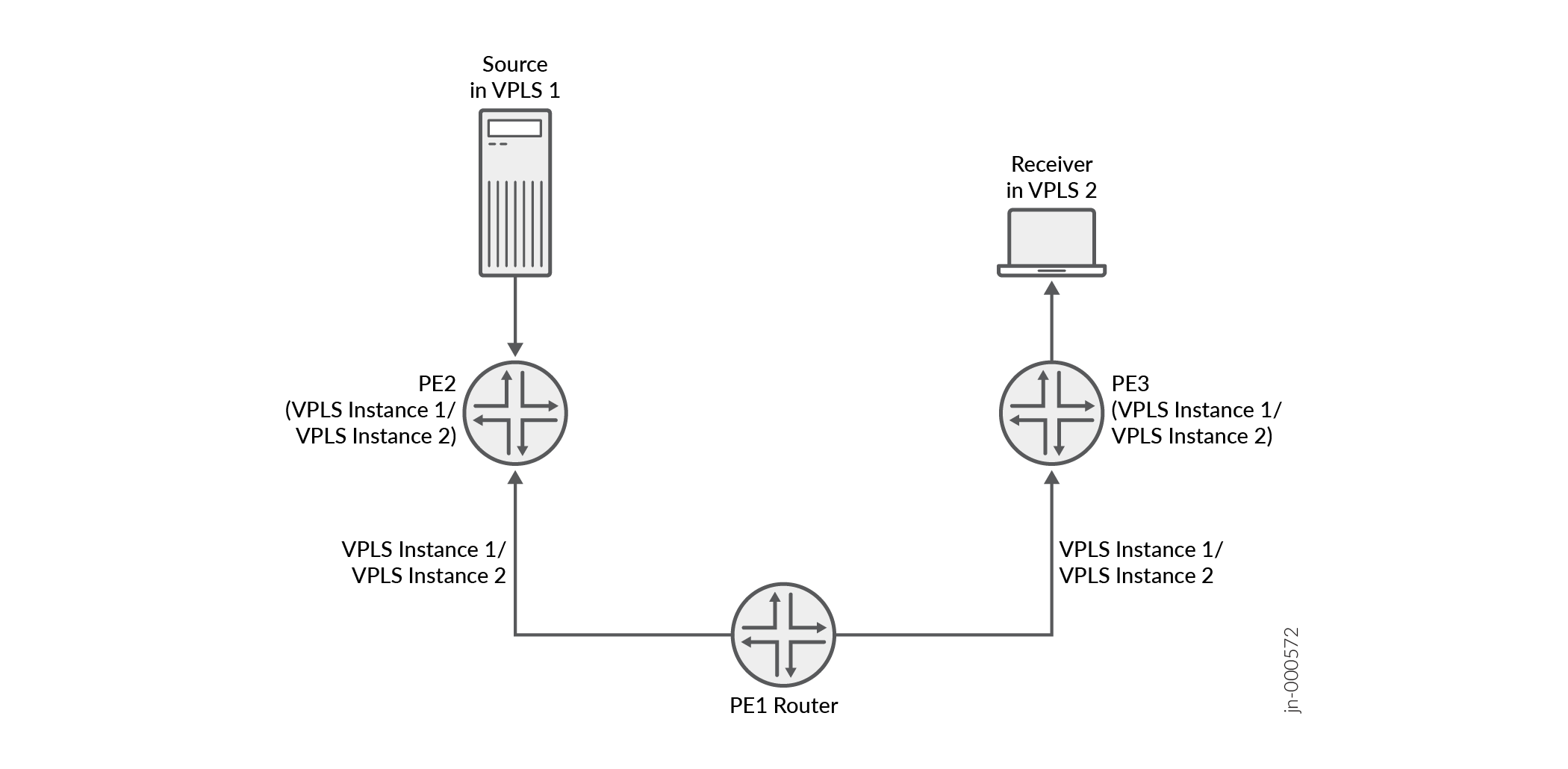
Disable routing on all PE routers except for the the centralized PE router to avoid traffic loops.
-
The source is external (L3 interface) and the receiver is in a VPLS domain. The IGMP/MLD queries are reinjected into the multicast router and LSI port. The multicast traffic is encapsulated and routed via the psuedowires.
-
The source is in a VPLS domain and the receiver is external (L3 interface). The VPLS multicast traffic is decapsulated and routed to the external interface.
-
The source is in a VPLS domain and the receiver is in the same VPLS. The VPLS multicast traffic is bridged within the VPLS bridge domain.
-
The source is in a VPLS domain and the receiver is in a different VPLS domain. The VPLS multicast traffic is routed across VPLS circuits and IRBs.