- play_arrow Overview
- play_arrow Configuring Protocol Independent Multicast
- play_arrow Understanding PIM
- play_arrow Configuring PIM Basics
- Configuring Different PIM Modes
- Configuring Multiple Instances of PIM
- Changing the PIM Version
- Optimizing the Number of Multicast Flows on QFabric Systems
- Modifying the PIM Hello Interval
- Preserving Multicast Performance by Disabling Response to the ping Utility
- Configuring PIM Trace Options
- Configuring BFD for PIM
- Configuring BFD Authentication for PIM
- play_arrow Routing Content to Densely Clustered Receivers with PIM Dense Mode
- play_arrow Routing Content to Larger, Sparser Groups with PIM Sparse Mode
- Understanding PIM Sparse Mode
- Examples: Configuring PIM Sparse Mode
- Configuring Static RP
- Example: Configuring Anycast RP
- Configuring PIM Bootstrap Router
- Understanding PIM Auto-RP
- Configuring All PIM Anycast Non-RP Routers
- Configuring a PIM Anycast RP Router with MSDP
- Configuring Embedded RP
- Configuring PIM Filtering
- Examples: Configuring PIM RPT and SPT Cutover
- Disabling PIM
- play_arrow Configuring Designated Routers
- play_arrow Receiving Content Directly from the Source with SSM
- Understanding PIM Source-Specific Mode
- Example: Configuring Source-Specific Multicast
- Example: Configuring PIM SSM on a Network
- Example: Configuring an SSM-Only Domain
- Example: Configuring SSM Mapping
- Example: Configuring Source-Specific Multicast Groups with Any-Source Override
- Example: Configuring SSM Maps for Different Groups to Different Sources
- play_arrow Minimizing Routing State Information with Bidirectional PIM
- play_arrow Rapidly Detecting Communication Failures with PIM and the BFD Protocol
- play_arrow Configuring PIM Options
- play_arrow Verifying PIM Configurations
-
- play_arrow Configuring Multicast Routing Protocols
- play_arrow Connecting Routing Domains Using MSDP
- play_arrow Handling Session Announcements with SAP and SDP
- play_arrow Facilitating Multicast Delivery Across Unicast-Only Networks with AMT
- play_arrow Routing Content to Densely Clustered Receivers with DVMRP
-
- play_arrow Configuring Multicast VPNs
- play_arrow Configuring Draft-Rosen Multicast VPNs
- Draft-Rosen Multicast VPNs Overview
- Example: Configuring Any-Source Draft-Rosen 6 Multicast VPNs
- Example: Configuring a Specific Tunnel for IPv4 Multicast VPN Traffic (Using Draft-Rosen MVPNs)
- Example: Configuring Source-Specific Draft-Rosen 7 Multicast VPNs
- Understanding Data MDTs
- Example: Configuring Data MDTs and Provider Tunnels Operating in Any-Source Multicast Mode
- Example: Configuring Data MDTs and Provider Tunnels Operating in Source-Specific Multicast Mode
- Examples: Configuring Data MDTs
- play_arrow Configuring Next-Generation Multicast VPNs
- Understanding Next-Generation MVPN Network Topology
- Understanding Next-Generation MVPN Concepts and Terminology
- Understanding Next-Generation MVPN Control Plane
- Next-Generation MVPN Data Plane Overview
- Enabling Next-Generation MVPN Services
- Generating Next-Generation MVPN VRF Import and Export Policies Overview
- Multiprotocol BGP MVPNs Overview
- Configuring Multiprotocol BGP Multicast VPNs
- BGP-MVPN Inter-AS Option B Overview
- ACX Support for BGP MVPN
- Example: Configuring MBGP MVPN Extranets
- Understanding Redundant Virtual Tunnel Interfaces in MBGP MVPNs
- Example: Configuring Redundant Virtual Tunnel Interfaces in MBGP MVPNs
- Understanding Sender-Based RPF in a BGP MVPN with RSVP-TE Point-to-Multipoint Provider Tunnels
- Example: Configuring Sender-Based RPF in a BGP MVPN with RSVP-TE Point-to-Multipoint Provider Tunnels
- Example: Configuring Sender-Based RPF in a BGP MVPN with MLDP Point-to-Multipoint Provider Tunnels
- Configuring MBGP MVPN Wildcards
- Distributing C-Multicast Routes Overview
- Exchanging C-Multicast Routes
- Generating Source AS and Route Target Import Communities Overview
- Originating Type 1 Intra-AS Autodiscovery Routes Overview
- Signaling Provider Tunnels and Data Plane Setup
- Anti-spoofing support for MPLS labels in BGP/MPLS IP VPNs (Inter-AS Option B)
- BGP-MVPN SD-WAN Overlay
- play_arrow Configuring PIM Join Load Balancing
- Use Case for PIM Join Load Balancing
- Configuring PIM Join Load Balancing
- PIM Join Load Balancing on Multipath MVPN Routes Overview
- Example: Configuring PIM Join Load Balancing on Draft-Rosen Multicast VPN
- Example: Configuring PIM Join Load Balancing on Next-Generation Multicast VPN
- Example: Configuring PIM Make-Before-Break Join Load Balancing
- Example: Configuring PIM State Limits
-
- play_arrow General Multicast Options
- play_arrow Bit Index Explicit Replication (BIER)
- play_arrow Prevent Routing Loops with Reverse Path Forwarding
- play_arrow Use Multicast-Only Fast Reroute (MoFRR) to Minimize Packet Loss During Link Failures
- play_arrow Enable Multicast Between Layer 2 and Layer 3 Devices Using Snooping
- play_arrow Configure Multicast Routing Options
- play_arrow Controller-Based BGP Multicast Signaling
-
- play_arrow Troubleshooting
- play_arrow Knowledge Base
-
- play_arrow Configuration Statements and Operational Commands
Example: Configuring IGMP Snooping on EX Series Switches
You can enable IGMP snooping on a VLAN to constrain the flooding of IPv4 multicast traffic on a VLAN. When IGMP snooping is enabled, a switch examines IGMP messages between hosts and multicast routers and learns which hosts are interested in receiving multicast traffic for a multicast group. Based on what it learns, the switch then forwards multicast traffic only to those interfaces connected to interested receivers instead of flooding the traffic to all interfaces.
This example describes how to configure IGMP snooping:
Requirements
This example uses the following software and hardware components:
One EX4300 Series switch
Junos OS Release 13.2 or later for EX Series switches
Before you configure IGMP snooping, be sure you have:
Configured the vlan100 VLAN on the switch
Assigned interfaces ge-0/0/0, ge-0/0/1, ge-0/0/2, and ge-0/0/12 to vlan100
Configure ge-0/0/12 as a trunk interface.
Overview and Topology
In this example, interfaces ge-0/0/0, ge-0/0/1, and ge-0/0/2 on the switch are in vlan100 and are connected to hosts that are potential multicast receivers. Interface ge-0/0/12, a trunk interface also in vlan100, is connected to a multicast router. The router acts as the IGMP querier and forwards multicast traffic for group 233.255.0.100 to the switch from a multicast source.
Topology
The example topology is illustrated in Figure 1.

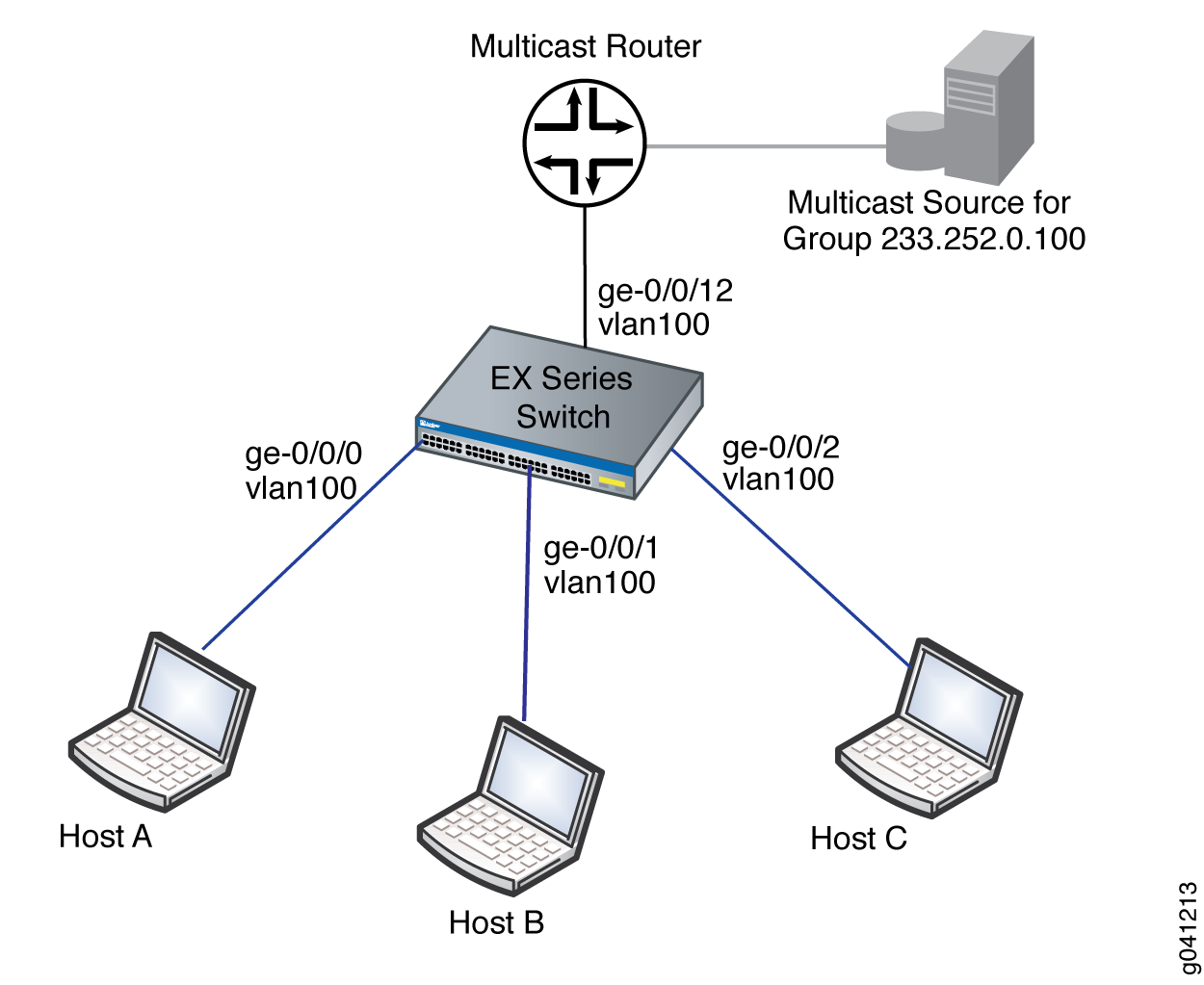
In this example topology, the multicast router forwards multicast traffic to the switch from the source when it receives a membership report for group 233.255.0.100 from one of the hosts—for example, Host B. If IGMP snooping is not enabled on vlan100, the switch floods the multicast traffic on all interfaces in vlan100 (except for interface ge-0/0/12). If IGMP snooping is enabled on vlan100, the switch monitors the IGMP messages between the hosts and router, allowing it to determine that only Host B is interested in receiving the multicast traffic. The switch then forwards the multicast traffic only to interface ge-0/0/1.
IGMP snooping is enabled on all VLANs in the default factory configuration. For many implementations, IGMP snooping requires no additional configuration. This example shows how to perform the following optional configurations, which can reduce group join and leave latency:
Configure immediate leave on the VLAN. When immediate leave is configured, the switch stops forwarding multicast traffic on an interface when it detects that the last member of the multicast group has left the group. If immediate leave is not configured, the switch waits until the group-specific queries time out before it stops forwarding traffic.
Immediate leave is supported by IGMP version 2 (IGMPv2) and IGMPv3. With IGMPv2, we recommend that you configure immediate leave only when there is only one IGMP host on an interface. In IGMPv2, only one host on a interface sends a membership report in response to a group-specifc query—any other interested hosts suppress their reports to avoid a flood of reports for the same group. This report-suppression feature means that the switch only knows about one interested host at any given time.
Configure ge-0/0/12 as a static multicast-router interface. In this topology, ge-0/0/12 always leads to the multicast router. By statically configuring ge-0/0/12 as a multicast-router interface, you avoid any delay imposed by the switch having to learn that ge-0/0/12 is a multicast-router interface.
Configuration
To configure IGMP snooping on a switch:
Procedure
CLI Quick Configuration
To quickly configure IGMP snooping, copy the following commands and paste them into the switch terminal window:
[edit] set protocols igmp-snooping vlan vlan100 immediate-leave set protocols igmp-snooping vlan vlan100 interface ge-0/0/12 multicast-router-interface
Step-by-Step Procedure
To configure IGMP snooping on vlan100:
Configure the switch to immediately remove a group membership from an interface when it receives a leave report from the last member of the group on the interface:
content_copy zoom_out_map[edit protocols] user@switch# set igmp-snooping vlan vlan100 immediate-leave
Statically configure interface ge-0/0/12 as a multicast-router interface:
content_copy zoom_out_map[edit protocols] user@switch# set igmp-snooping vlan vlan100 interface ge-0/0/12 multicast-router-interface
Results
Check the results of the configuration:
[edit protocols] user@switch# show igmp-snooping vlan all; vlan vlan100 { immediate-leave; interface ge-0/0/12.0 { multicast-router-interface; } }
Verifying IGMP Snooping Operation
To verify that IGMP snooping is operating as configured, perform the following task:
Displaying IGMP Snooping Information for VLAN vlan100
Purpose
Verify that IGMP snooping is enabled on vlan100 and that ge-0/0/12 is recognized as a multicast-router interface.
Action
Enter the following command:
user@switch> show igmp-snooping vlans vlan vlan100 detail
VLAN: vlan100, Tag: 100
Interface: ge-0/0/12.0, tagged, Groups: 0, Router
Meaning
By showing information for vlan100, the command output confirms that IGMP snooping is configured on the VLAN. Interface ge-0/0/12.0 is listed as multicast-router interface, as configured. Because none of the host interfaces are listed, none of the hosts are currently receivers for the multicast group.